LUBRICANT OIL DISPERSANCY TESTER - OPERATION MANUAL
←
→
Page content transcription
If your browser does not render page correctly, please read the page content below
DT 100 OPERATION MANUAL

LUBRICANT OIL DISPERSANCY TESTER

1        Doc : AM110-001E Release: 1.2.4.4 updated : Aug2010
2 Doc : AM110-001E Release: 1.2.4.4 updated : Aug2010
INFORMATION
                                                                               INFORMATION
Information in this document is subject to change without notice and does not represent a commitment
on the part of AD systems.
AD systems provides this document “as is”, without warranty of any kind, either expressed or implied,
including, but not limited to, the particular purpose.
AD systems may make improvements and/or changes in this manual or in the product(s) and/or the
program (s) described in this manual at any time. This product could include technical inaccuracies or
typographical errors. Changes are periodically made to the information herein; these changes may be
incorporated in new editions of the publication. Reproduction of any part of this manual without express
written permission is forbidden.

      3                          Doc : AM110-001E Release: 1.2.4.4 updated : Aug2010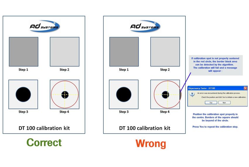
CAUTION
This analyzer has been carefully designed, manufactured and inspected for
quality. It has been equipped with a number of safety features.
However, the use of this analyzer may involve the handling of solvents,
chemicals, and other potentially dangerous flammable, toxic, etc. materials.
Please exercise caution when handling these materials while operating the
analyzer.
Please:
Read the operating manual
Wear proper protective clothing
Perform all suggested service procedures
Use care to prevent accidents.
The manufacturer accepts no responsibility for any damage or liability arising
from the use of analyzers.
Use of Non AD systems Products and Accessories: defects or damage that result
from the use of Non-AD systems branded or certified Products, Accessories,
Software or other peripheral equipment are excluded from warranty.
Do not return the analyzer or any part to the factory without prior factory
authorization.
4 Doc : AM110-001E Release: 1.2.4.4 updated : Aug2010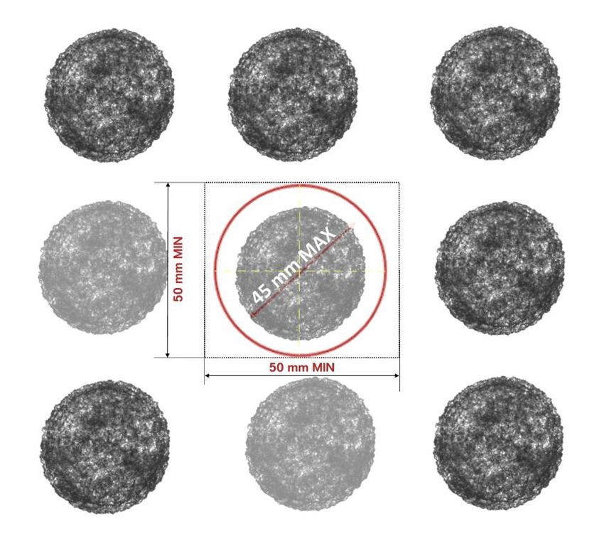
Correct disposal of Waste Electrical and Electronic Equipment
                                                 in the end-of life

Applicable in the European Union and other European countries with separate collection systems

                    This product is designed for exclusive professional use by commercial companies. This
                    marking shown on the product or its literature, indicates that it should not be
                    disposed with other household wastes at the end of its working life. To prevent
                    possible harm to the environment or human health from uncontrolled waste disposal,
                    please separate this from other types of wastes and recycle it responsibly to promote
                    the sustainable reuse of material resources. Business users should contact the
                    producer or the importer and check the terms and conditions of the purchase
                    contract. If you have a separate agreement with your producer or your importer on
the end-of-life disposal in a way that you will care for disposal by your own, would you please ensure an
environmentally sound disposal according to the legal regulations for electric and electronic waste
equipment in your country.
This product should not be mixed with other commercial wastes for disposal.

The above WEEE-symbol is the official marking for equipment under the WEEE-scope. In some EC-
Member states "pure B2B equipment" is not necessarily marked with the waste bin symbol. To provide a
homogenous EC-wide procedure, AD systems however uses the marking in all EC-Member states.

      5                          Doc : AM110-001E Release: 1.2.4.4 updated : Aug2010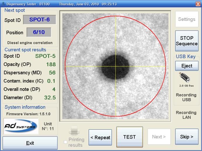
CONTENTS

CONTENTS ....................................................................................................................................................... 6
APPLICATION................................................................................................................................................... 7
DT100 OPERATION PRINCIPLE ........................................................................................................................ 8
HOW TO PREPARE THE OIL SPOT ................................................................................................................... 9
ANALYZER UNPACKING ................................................................................................................................ 12
DESCRIPTION................................................................................................................................................. 13
SETUP ............................................................................................................................................................ 14
SWITCHING ON ............................................................................................................................................. 14
CALIBRATION ................................................................................................................................................ 15
 How to repeat the calibration without switching off the instrument....................................................... 16
 Error message during calibration. ............................................................................................................. 17
MAIN SCREEN................................................................................................................................................ 18
  MAIN SCREEN DESCRIPTION ..................................................................................................................... 18
  PROGRAMMING TEST SEQUENCE ............................................................................................................. 19
HOW TO PERFORM A TEST ........................................................................................................................... 23
   MEASUREMENT – GENERAL OPERATION .................................................................................................. 23
   MEASUREMENT – SPECIFIC CASES ............................................................................................................ 26
    CASE 1 : “Spot is out of viewing area” message ................................................................................... 26
       CASE 2 : Stopping current test sequence ............................................................................................. 27
       CASE 3 : Manual data transmission to USB device or to LAN ............................................................... 27
RESULTS REPORTED ...................................................................................................................................... 28
  PARTICULAR CASES OF REPORTING .......................................................................................................... 28
  Details on the image processing and calculation algorithm ..................................................................... 30
SETTINGS ....................................................................................................................................................... 31
   USB data storage ....................................................................................................................................... 32
   Local Network (LAN) data transmission .................................................................................................... 33
     Section Record Data .............................................................................................................................. 33
       Section File Information ........................................................................................................................ 33
       Section “Storage mode” ........................................................................................................................ 33
       Spot images storage options : ............................................................................................................... 35
  How to set Date and Time ......................................................................................................................... 38
  Firmware Update....................................................................................................................................... 38
PRINTOUT...................................................................................................................................................... 41
SERVICE ......................................................................................................................................................... 42
SPARE PARTS ................................................................................................................................................. 44
REVISIONS ..................................................................................................................................................... 46

          6                                         Doc : AM110-001E Release: 1.2.4.4 updated : Aug2010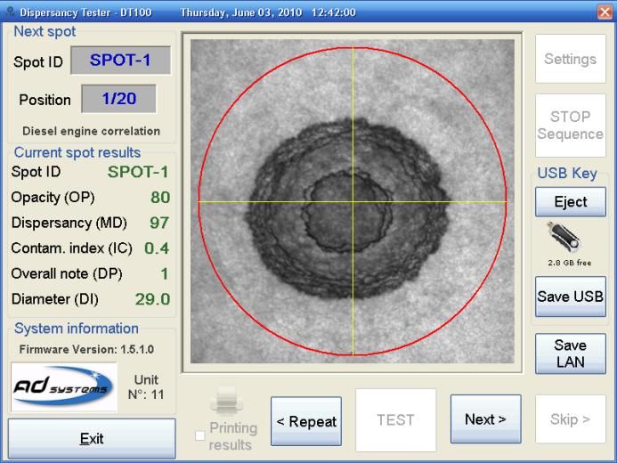
APPLICATION
The blotter spot test dates back to the early 1950s. It is one of the oldest techniques used to identify
excessive engine soot, evaluate a lubricant’s dispersancy and detect the presence of glycol, fuel and other
contaminants in engine crankcase lubricants.

For large fleet operators, oil conditioning monitoring laboratories, this simple, yet powerful technique can
provide valuable information when used as a screening tool.

Though this method has proven effective, individual subjectivity in readings oil spots affects the reliability
of results.

To help oil analysts taking most advantage of this valuable traditional technique the company AD systems
in cooperation with a lab dedicated in Oil Conditioning Monitoring (OCM) has developed a modern
automatic instrument offering significant increase in accuracy and repeatability of measurements.
The DT100 is the only instrument that automatically and simultaneously measures the dispersancy and
the soot contamination of the lubricating oil.

This new technique removes all the arbitrary aspect of the manual method.
The oil spot is illuminated with a stable and consistent light source. A CCD camera takes a picture of the
oil spot in monochrome mode and with backlighting. In couple of seconds the sophisticated software
scans and analyses all the different areas of the oil spot calculating valuable in-use oil quality parameters.

- The dispersancy (MD) is key indication about the detergent capacity of the oil to disperse and melt
particles. MD is expressed by an index from 100 (ideal) to 0 (no dispersancy)

 - The contamination index (IC) representing the percentage of insoluble matters in the oil (measurement
limits: 0.1 to 4.8%).

- The Weighted Demerit (DP) which is a mathematical combination of the two above mentioned
parameters DP = (100 –MD) * IC. The DP is essential parameter for trend monitoring.

Optional version of DT100
The DT100 DL (Dual Light) version of the instrument is equipped with color camera and additional direct
light source. Then calculations are done, the DT100 DL switchs the camera in color mode, turn off the
backlight illumination and flash the spot with front light in order to record color image of the spot in
direct lighting as it is seen by human eyes.
Both spot images : monochrome picture and with backlighting and color picture in direct lighting are
stored on USB device or sent to local network.
In addition, the DT100DL offers sample ID “tagging” by stamping the sample ID into the spot bitmap
image.
The DT100DL offers full test traceability. The spot image is easily identified along with reported results
making it ideal for quality process documentation, reporting and electronic archiving.

       7                           Doc : AM110-001E Release: 1.2.4.4 updated : Aug2010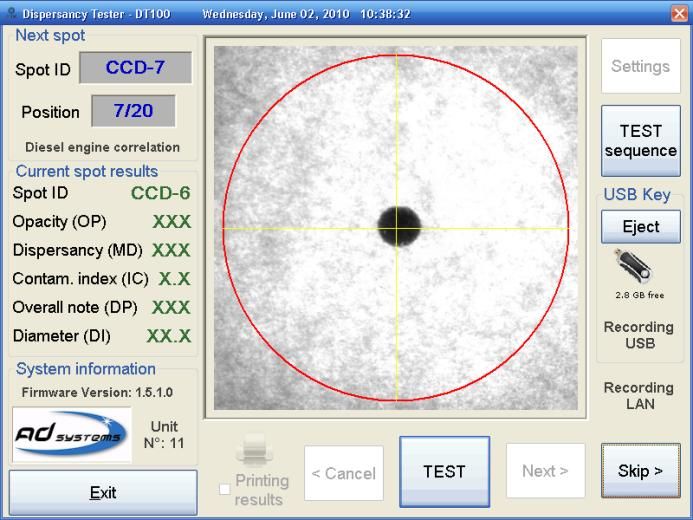
DT100 OPERATION PRINCIPLE
The oil spot is illuminated with a constant light source. A CCD camera takes a picture of the oil spot and
the software calculates the different parameters.

                                                             Image processing
                                                                algorithm

                                                                                      Digital
                                                                                      camera

                                                                           Spot

                                       Backlight source

DT100 Technical information

Technical points                          Description
Duration of one oil spot analysis         Few seconds for each measurement
Number of oil spots per paper sheet       Up to 16 spots
Max diameter of the spot                  45 mm
Positioning of the oil spot               Visual centering of the oil spot with the DT 100 display
Spot image storage                        Black & white image in back lighting
Results storage capacity                  Unlimited, depends on the disk on key capacity
Calibration of imaging system             Special calibration tool (delivered with the unit)
Printer output                            Via USB link, the printer is optional
Data output                               2 x USB ports, Ethernet RJ45 port
Dimensions (mm), weight                   W x D x H = 305 x 487 x 390; 20 kg
Electrical                                115 to 230V – 0,5 A - 50 / 60 Hz

       8                            Doc : AM110-001E Release: 1.2.4.4 updated : Aug2010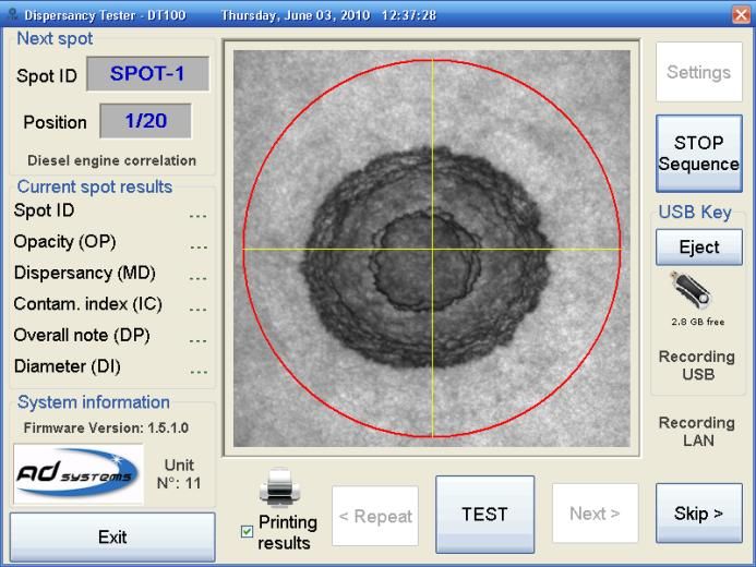
HOW TO PREPARE THE OIL SPOT
The spot method (or blotter test) is a simple but valuable test that provides unique information on oil
dispersancy for laboratory oil conditioning analysis program.
A drop of oil is poured on a filter paper
The drop spreads on the paper
The oil with contained particles penetrates into the filter paper. Due to the lamination phenomenon of
the oil film, the particles of same size depose on the paper on the same concentric zone. The distribution
of the different zones will reflect the status of the used oil.
Caution!
Quality of the oil spot and, as consequence, the quality of measurement depends on the filter paper
grade.
When the instrument is used in Oil Conditioning Monitoring program, the proper oil trend monitoring is
of importance. To obtain repeatable and reproducible oil dispersancy results, it is essential to use high
quality filter paper of the same grade.
We strictly recommend using the filter paper Durieux type 122 (Ordering Part Number: AC110-001).
Please contact AD systems for information.
Important!
Besides the proper grade of the filter paper, other factors can influence the oil spot.
In order to obtain precise and reproducible test results, the following requirements need to be carefully
respected:
- Use the recommended filter paper grade (as mentioned above)
- Drop the oil sample in the centre of the hole in the holder (use Drop Guide for micropipette available
from AD Systems – refer to the section “Spare Parts” of this manual)
- Respect the oil volume of 20 L. Use the dosing pipette. Higher or lower sample volume will result in
different size of the oil spot after drying. This will affect the measurement of MD and DP parameters.
- Always use the paper holder during drying to prevent the filter paper of creasing or warping
- During drying phase, keep the paper holder in horizontal position. Inclination of the holder during
drying can result in developing non-circular shape of the oil spot. This can affect the precision of the
measurement.
- The filter paper with oil drop should be free from touching any surface or object during spot
development.
- Before the measurement remove the paper sheet out of its holder.
9 Doc : AM110-001E Release: 1.2.4.4 updated : Aug2010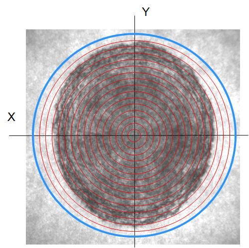
Procedure of oil spot preparation:
1. Take a filter paper sheet and position it in the filter paper holder
2. Shake the container with the oil sample to be analyzed.
3. With a micro pipette able to precisely dose 20 l of oil, take 20l sample of oil.
4. Wipe the outer surface of the pipette tip from the excess of the oil and pour the sample in the center
of the hole provided in the holder. We recommend to use the Drop Guide for micropipette available
from AD Systems (refer to the section “Spare Parts” of this manual)
The guide (P/N AK110-004) is placed on the hole in the filter holder and assures vertical position of the
micro-pipette tip in the center of the hole and always on the same distance to the filter paper. The
technician needs just to push the piston to get perfect drop.
AK110-004 AK110-005 / AK110-006
For labs running many tests a day, can use a guide assembly of 4 places (P/N AK110-005 and AK110-006)
which helps to improve test precision and save time on spot preparation.
The AK110-005 is designed for a row of 4 holes of 50mm with step of 52mm.
The AK110-006 is designed for a row of 4 holes of 50mm with step of 65mm.
Note: 16 oil spots can be prepared on one single sheet of 260x260mm. However, in general, only 15 oil
spots are prepared and the sample batch number is written on the upper corner of the paper sheet.
If you follow this notice, please write the batch number first, before sampling; in order to not disturb oil
spots development afterwards.
5. The paper holder with the paper sheet is then placed in horizontal position for 60 minutes in
laboratory drying oven adjusted at 80°C.
6. After 60 minutes, remove the paper holder from the oven.
10 Doc : AM110-001E Release: 1.2.4.4 updated : Aug2010Caution!
The holder metal surface will at 80°C, use protecting gloves to take out the holder from the oven
7. The paper filter is extracted from the holder and oil spots can be analyzed with the DT 100.
Important!
After the 60 minutes drying phase @80°C, the oil spot may continue
its expansion.
In order to obtain precise results, the oil spot must
be analyzed within 15 minutes after the extraction of
the filter paper from the oven.
11 Doc : AM110-001E Release: 1.2.4.4 updated : Aug2010ANALYZER UNPACKING
Care in Unpacking
After unpacking, verify the unit and its accessories as well as any possible damage sustained in transit,
which must immediately brought to the attention of the carrier so that a statement of damage can be
made.
If equipment damage exists, keep the equipment, crates and packaging materials and file a claim with the
final carrier. Usually, the carrier will send an inspector to ascertain liability. Send a copy of the claim to AD
systems or to its local distributor.
Please refer to the following website to get address details: www.adsystems-sa.com
Note: Do not return the analyzer or any part to the factory without factory authorization.
Packing list:
1 x DT 100 Instrument
1 x Power cord
1 x Pack of 100 sheets of filter paper (Durieux type 122 or equivalent)
5 x Sets of filter paper holders
1 x Calibration sheet
1 x Operating manual
The various parts of the analyzer are carefully verified and tested before shipping. Nevertheless, it is
worth verifying that the equipment received corresponds to the packing list enclosed.
12 Doc : AM110-001E Release: 1.2.4.4 updated : Aug2010DESCRIPTION
The DT100 instrument presents as follow:
1 – Touch screen
2 – Test button
3 – USB A connector for connection of disk on key
4 – USB B connector for connection of an external printer
5 – RJ45 Ethernet connector for connection to the LAN network
6 – Power supply cord connection, fuse and power supply switch
7 – CCD camera enclosure
8 – Testing area to place the paper sheet
1
7
8
2 7
3
Front view
4
6
5
Rear view
Main Power Connection
The DT 100 analyzer operates from 100 to 240 Volts, at 50 or 60 Hz, in accordance with the majority of
countries where the analyzer is marketed. Plug the power cord to the instrument and to the main plug.
License notice:
The DT 100 is using a Windows XPE platform. The license label is located inside the lower part of the
electronic cabinet. Please do not remove this sticker!
13 Doc : AM110-001E Release: 1.2.4.4 updated : Aug2010SETUP
Put the DT 100 on a horizontal flat workbench and not subject to vibrations, near electrical sockets.
Provide enough space so that the analyzer can be operated conveniently and for access to the rear
connectors.
Remove the transportation holding device
Note: Transport the analyzer only with holding device in place!
Remove the touch screen protection film
Note:
Do not install the DT 100 in a place with direct sunlight.
Put the analyzer away from strong lighting sources; it can affect the measurement.
Leave sufficient space behind the analyzer for cabling access and for clear ventilation.
Do not cover the air intake slots of the unit. Failure of sufficient air ventilation can cause
instrument damage.
Before transporting the analyzer, install the holding device between work plate and the
upper part
SWITCHING ON
CAUTION!
Once the analyzer has been unpacked, before switching-on, allow sufficient time (a few
hours) so that the analyzer adjusts to the laboratory temperature (especially if it has been
stored at low temperatures and/or at high humidity conditions).
Press the Main Power Switch on the back side of the analyzer to the ON position (see rear view
picture).
Verify the followings:
• The light in the lower part of the cabinet is on
• The screen lights up and the Welcome Screen is displayed (see section below)
• A self diagnostic test is initiated
After about twenty seconds a window will be displayed inviting to proceed with the calibration of the
instrument. Make the calibration as explained in the next section of the manual.
14 Doc : AM110-001E Release: 1.2.4.4 updated : Aug2010CALIBRATION
Strict factory verification, adjustment and calibration of the DT100 imaging system components (camera,
lens, backlight) are made by AD systems before the delivery of the instrument
At daily use of the instrument, routine verification and calibration of imaging system is performed at
every switch on
Camera brightness and contrast are adjusted by measuring 2 standard filters of known
opacity (neutral density filters ND)
Dimension measurement is verified by measuring 2 spots of known diameter
All necessary means for the DT100 calibration is included into one single accessory – “DT100 Calibration
Kit”, which supplied with every instrument.
Dark Light
calibration calibration
filter filter
Calibration Calibration
spot 35 mm spot 20 mm
The DT 100 calibration procedure is achieved in four steps following on-screen instructions.
Open the DT 100 Calibration tool folder, take the calibration kit and place it under CCD Camera.
Position the appropriate part of the calibration kit within the red circle. Press OK once it is correctly
centered.
STEP1 STEP2 STEP3 STEP4
15 Doc : AM110-001E Release: 1.2.4.4 updated : Aug2010When the calibration phase is achieved; the following
message is displayed:
Press OK to switch to the measuring menu.
The instrument is now ready to perform a test. To do
so, the Test Sequence has to be defined.
Caution !
Store the Calibration Kit in a dry and dark place. Protect it from temperature variations.
Keep it in its folder protecting from accidental mechanical damage and direct light.
How to repeat the calibration without switching off the instrument
At any time there is a possibility to repeat the Calibration routine. If it is required, go to menu “SETTINGS”
and select “Init Calibration”.
After the confirmation the calibration will be requested before to start any new measurement.
16 Doc : AM110-001E Release: 1.2.4.4 updated : Aug2010Error message during calibration.
In case of calibration failure, please make sure of the following:
1. The lighting window is clean. Refer to the section “Service” of this manual.
2. The right DT 100 calibration tool is used
3. The filters (step 1 and 2) are not scratched or dirty.
4. If an error message occurs on Step 3 or Step 4, please be sure that one of calibration spot is not
dirty or damaged.
5. The calibration spot is properly centered in the red circle. Typical error in the positioning is
illustrated here below :
If one of 4 parts of the Calibration Kit appears to be damaged or dirty, replace the Calibration Kit –
AD systems ordering part number is AK110-002.
If the Calibration Kit looks fine, but the error message persists, contact AD Systems or its local distributor.
17 Doc : AM110-001E Release: 1.2.4.4 updated : Aug2010MAIN SCREEN
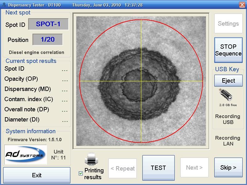
The DT 100 is now ready for oil spot measurement.
MAIN SCREEN DESCRIPTION
The main screen is as follow:
Buttons :
Settings – to set data and results format to be stored on external drive or LAN.
SET Sequence – to program the sample ID, number of spots and select the correlation type. This is the
menu to start with before testing a first sample.
TEST – to measure a spot. Every spot measurement is performed by pressing “TEST” button. In general
operation mode with validation, at the completion of a measurement the test results are displayed and
the spot image remains “frozen” on the screen allowing visual check for the results and the spot. The
operator should press “Next>” button to validate current results and go to the next spot in the sequence.
There is also test mode without validation. See more details below in the manual.
Next> - is to validate current spot measurement and go to the next sample in the sequence
- is to skip a spot in test sequence without measurement
Exit – to quit the DT100 application and switch off the instrument.
Other buttons / messages :
Eject – to eject the USB storage device if connected. The software automatically recognizes the storage
device. Always use “Eject” button to remove storage device safely.
Printing results – this check box is active when printer connected. Refer to “Printing” section of the
manual for more information.
Recording USB – a message of confirmation that results automatically stored to the USB device. Refer to
section “Data storage” of the manual for more information.
Recording LAN – a message of confirmation that results automatically send to LAN. Refer to section “Data
storage” of the manual for more information.
18 Doc : AM110-001E Release: 1.2.4.4 updated : Aug2010PROGRAMMING TEST SEQUENCE
After calibration the DT 100 is ready for oil spot measurement.
To perform a measurement, test sequence identification has to be entered first. Under the term “test
sequence” we understand a sheet of filter paper with number of spots to be tested.
SET Sequence menu – is to define mode of testing, the sample ID, number of spots and the correlation
type to be used for series of spots.
Press “SET sequence” button. The following menu will appear:
In the SET Sequence menu there are a few options allowing flexibility in programming.
Spot Name mode
Sequence ID is mandatory for start testing.
The name of the test sequence will be used as a filename to store result data on USB
On your choice, three modes for spot identification are available:
Incremental Sequence ID. If this box is checked, the Sequence ID should be a number.
Touch the red area to enter the value. The maximum number of characters for sequence ID is 6 numbers.
Each next spot will have automatically incremental number starting from to the number of first spot.
For example, you have to test 20 spots on the filter sheet :
Sequence ID: 48501
Spot Qty: 15
The first spot will get the ID: “48501”, the next – “48502”, “48503”, 48504”… till “48515”
Sequence ID extension. If this box is checked, it is possible to give a sequence name with alpha-numerical
characters. Touch the red area to enter the value. The maximum number of characters for sequence ID is
6 alpha-numerical characters.
19 Doc : AM110-001E Release: 1.2.4.4 updated : Aug2010Each spot will keep the sequence ID and add an order number for every spot separated with a dash.
For example (as shown on the picture below), you have to test 20 spots on the filter sheet :
Sequence ID: SPOT
Spot Qty: 20
First spot will get ID: “SPOT-1”, the next – “SPOT-2”, “SPOT-3”, etc… till “SPOT-20”
Typing name for each spot. If this box is checked, the systems will ask individual spot name for every
spot in the sequence. The entry will be possible with virtual alpha-numerical keypad from the main screen
each time after pressing “TEST” button. In this mode there is no global sequence name.
Sequence settings
Sequence ID - test sequence name.
Spot Qty – number of spots in the sequence. Maximum number is 99.
In order to make an entry for Sequence ID and Spot Qty , touch the area highlighted in red. The virtual
keypad will appear allowing you to enter the required information.
Proceed in the same way to call the virtual keypad in other cases.
20 Doc : AM110-001E Release: 1.2.4.4 updated : Aug2010Measurement validation. Every spot measurement in the test sequence is performed by pressing “TEST” button. In general operation mode, at the completion of a measurement the test results and spot image is displayed and remains “frozen” on the screen allowing visual check the results and the spot. The operator should press “Next>” button to validate current results and go to the next spot in the sequence. To accelerate testing there is a mode ‘Without Validation”. If the box “Without Validation” was checked at programming the test sequence, the systems will don’t ask validation of every spot measurement by pressing “Next>” button. The data will be processed, stored, transmitted to LAN and printed at single press of “TEST” button. Be careful then using this mode if the DT100 is connected to network with data processing by LIMS system. The button “
Pressing “No” allows repeating the last spot in the sequence.
Press “Yes” to terminate the test sequence.
This is necessary for proper closing the test result file in LAN or USB.

Engine correlation
Select the proper Engine Correlation for oils to be tested. This correlation is used to report Contamination
Index (IC). There are two correlations available: one for Diesel Engine lubricating oil and one for Marine
Engine lubricating oils. Use the proper correlation for the type of lubricants you are testing.

Press “Accept” to validate settings and leave the menu.

Button “Set as default” allows storing the current settings as default values. Use this button when you do
similar settings for majority of your spots. Then next time you will press the SET Sequence button the
system will set default values automatically. If there are no changes, you can just press “Accept”.
It is always possible to enter new Sequence ID and Spot Qty. If default values were set, it will valid for one
sequence only.
In order to change default settings, enter new values or delete all values and press “Set as default”.

     22                            Doc : AM110-001E Release: 1.2.4.4 updated : Aug2010
HOW TO PERFORM A TEST
Enter the Test Sequence settings as explained above.
MEASUREMENT – GENERAL OPERATION
Enter the Test Sequence settings as explained above.
Place the paper sheet on the testing area.
Filter paper sheet can contain any number of spots. The most practical is 16 spots on the filter sheet
dimensions 260x260mm.
Caution !
For proper operation of the image processing algorithm the following requirements should be respected:
- Maximum spot diameter should not exceed 45 mm. It should be entirely in the red circle area.
- The area of minimum 50x50mm around the spot should be free of any marks or neighbor spot.
See picture below.
The instrument DT100 will illuminate the backlight lighting. Place
the first oil spot to be tested under the CCD camera and check its
positioning on the screen.
Position the filter paper to center the first spot in the programmed
sequence within the red circle shown on the display. Yellow cross
helps to align the estimated center of the spot in the center of the
testing area.
Although the DT100 image processing algorithm has no strict
requirement for perfect center alignment, the uniform orientation
of spot under the camera helps improving repeatability of results.
Because oil spots have typically non-round, oval shape it is advised
to keep the same orientation.
A spot is positioned under the camera :
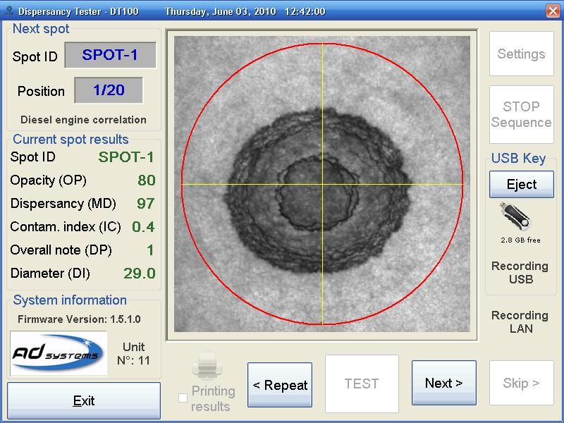
23 Doc : AM110-001E Release: 1.2.4.4 updated : Aug2010When the spot is correctly positioned in the red circle, press the “TEST”
button on the touch screen or press the “Test” button on the front panel to
measure the sample.
Then the button TEST has been pressed, the DT100 instrument will do following
operations :
- Take a spot image in backlight illumination
- Analyze the image to indentify the spot edges
- Check if the spot properly positioned within the red circle.
- Process the spot image to calculate oil quality parameters : IC and MD
- Measurement results will be displayed on the left side of the image area (see section “Results
reported”). The resulting spot image is displayed and remains “frozen” on the screen allowing visual
check the results and the spot.
- Press “Next>” button on the touch screen or push one more time the “Test” button on the front
panel to validate the measurement and go to next spot. In case of doubts in results, it is possible to
redo the spot again. Press “” button signifies validation of current test result.
24 Doc : AM110-001E Release: 1.2.4.4 updated : Aug2010At this moment, depends on the result storage configuration (please refer to the section “SETTINGS” of
the present manual for more details on available storage options), the DT100 instrument will do following
operations:
- Transfer result to LAN via Ethernet link
- Store result to USB storage device
- Print result (if printer is connected and printing was requested)
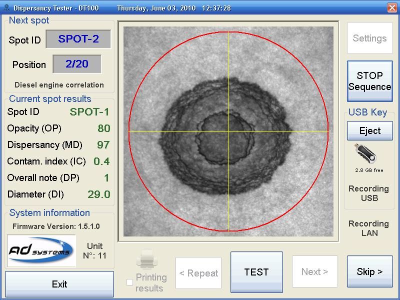
After the button “Next>” been pressed, the instrument is ready to test next spot. The main screen
will keep results of the previous spot and indicate next spot position to be tested.
Expected
next spot
position
Results of last
tested spot
Position under the camera the next spot in the sequence and proceed as indicated above for the first one.
When the programmed test sequence had been completed, a blinking
message will appear: “ Sequence Completed”.
Set a new test sequence to measure the next batch of samples.
25 Doc : AM110-001E Release: 1.2.4.4 updated : Aug2010MEASUREMENT – SPECIFIC CASES
CASE 1 : “Spot is out of viewing area” message
- After pressing ‘TEST” button, the DT100 process digital image of the viewing area. If the DT100
detects that the spot is our of the circle, a message will be displayed asking to re-position the spot
and repeat the measurement
Position the spot properly and press “TEST” again.
If this message persists, it can be due to following reasons :
- The spot is not positioned correctly within red circle
- The spot diameter is big – bigger than the red circle area
- Dirt or writing marks near to the spot
Important! The reason of “Spot not detected” message could be due to presence of dirt or writing marks
in the corners of viewing area outside of the red circle. The system is using corners of viewing area to
sample the paper background image. Take care that the filter paper around of spot is clean. If not, the
spot cannot be detected properly.
In case if a spot cannot be properly tested or there is other reason to omit measurement of this spot in
test sequence, there is a possibility to skip its testing by pressing “Skip>” button on touch screen.
When “SKIP>” button was pressed:
- Spot ID number increasing
- No analyze of spot image, no measurements, no analyze if spot is within red circle
- Picture of spot is taken but not sent to LAN and not stored on USB (if programmed)
26 Doc : AM110-001E Release: 1.2.4.4 updated : Aug2010- All result data fields for skipped spot will be filled with default values “XX”:
o Opacity (OP): XXX
o Dispercancy (MD): XXX
o Contam.index (IC): X.X
o Overall note (DP): XXX
o Diameter (DI): XX.X
- These default values are shown on the screen, stored in the file (LAN or USB) and printed
CASE 2 : Stopping current test sequence
At any time it is possible to stop the test sequence in progress.
Press button “STOP sequence” on the main screen.
Confirm “Yes” to stop the test sequence.
CASE 3 : Manual data transmission to USB device or to LAN
Please refer to section “Settings / Local Network (LAN) data transmission” for all possible settings.
In case if “Auto Storage” option was not selected, there is a possibility to store results manually.
Press button “Save USB” or “Save LAN” on the main screen in order to store test data before to press
“Next>” button.
Note : If the data transmission mode is set to “Auto storage” these buttons will not appear. Instead, you
will get a message “Recording LAN” and “Recording USB” that means the data are automatically saved
without manual validation.
27 Doc : AM110-001E Release: 1.2.4.4 updated : Aug2010RESULTS REPORTED
Spot ID: spot identification in the sequence
Opacity: average opacity of the oil spot
MD: Dispersancy
It varies in accordance with the homogeneity of the zones and the size of
the oil spot
It is expressed by an index from 100 (ideal) to 0 (no dispersancy)
The instrument report MD value rounded to integer.
IC: Contamination Index
Measurement limits: 0.1% to 4.8 %
It is obtained with a correlation established with IFP 303 method.
DP: Overall Note
Overall Note (DP) is used for trend monitoring and gives global assessment of the oil quality.
DP value is a combination of IC and MD and it is expressed as an index from 0 (ideal) to 200+ (very poor)
The calculation is as follow: DP = (100 –MD) * IC.
Note: For DP calculation the instrument uses MD value not rounded to integer in order to increase
sensitivity of the DP value.
DI: Diameter
Calculated average spot diameter in mm.
PARTICULAR CASES OF REPORTING
Particular Case 1 – Dark spots
When the spot is too dark (opacity is lower than the defined threshold), the system will automatically
change camera exposure mode in order to get contrasted image. In that case the spot picture on the
screen will momentarily change as a fast flash. It is
normal operation of the instrument.
The camera switch allows for a better distinction
of grey levels within very dark spots. This special
mode improves correlation of Contamination
Index (IC) for heavily contaminated oils.
In case of very dark spot, the DT100 software will
display two values for OP: in normal mode and in
high exposure mode. The second value is
displayed in brackets for information only.
28 Doc : AM110-001E Release: 1.2.4.4 updated : Aug2010Particular Case 2 – Dark spot, IC is out of correlation range
If the spot is too dark and measured opacity value is over of valid range
for IC correlation, the instrument will report IC >4,8% for Diesel oil
correlation and IC >5,6% for marine oil correlation. Because the DP value
cannot be calculated in this case, the instrument will report DP = OUT.
Example of reporting for such case for diesel oil correlation is shown on
the right.
The IC value “>4.8” and DP value “OUT” will be printed, saved on USB
key and sent to LAN/LIMS.
Particular Case 3 – Indistinguishable spot
This specific case occurs when the spot opacity is very close to those of
the filter paper. The DT100 detection algorithm cannot distinguish the
spot from the background (paper).
In this specific case the software will take a default spot diameter of 20
mm. In the test report this will be indicated by an apteryx sign, as
shown on the example picture.
Important! If the system is unable to determine the spot edges, it will
take the center of the image area (cross point of yellow lines) as a spot
center. In such case, it is particularly important to properly center the spot in the red circle in order to
get repeatable results of MD and IC.
Particular Case 4 – Skipped spot in the test sequence
Running a test sequence the operator can decide to skip a doubtful spot
by pressing “SKIP>” button. In such case, all report fields will be filled
with “XX” values. These values will be printed, saved on USB key and
sent to LAN/LIMS.
29 Doc : AM110-001E Release: 1.2.4.4 updated : Aug2010Details on the image processing and calculation algorithm
Details on the image processing and calculation algorithm employed in DT100 analyzer.
The automatic measurement of oil spot by the
DT100 instrument is achieved in four steps:
1. Image processing for spot identification:
a. Search spot
b. Determine edges
c. Determine centre of the spot
d. Eliminate filter paper effects
2. The mean opacity (OP) and the mean diameter of the oil spot (DI) are calculated.
Contamination Index (IC) is determined with a correlation table based on opacity measurement.
3. The MD (Dispersancy Merit) calculation.
Dispersion characteristics of the oil are judged by how far
oil drop spreads, how big the central sooty area is and how
homogeneous the opacity of the spot is in comparison
with a theoretical reference diameter of 32mm (blue circle
on the illustration picture). The MD calculation is done in 3
steps :
a) First, homogeneity of soot distribution within the spot
is assessed by « demerit » value (not reported). The oil
spot is divided from its center in 16 concentric zones.
For each zone the average concentric opacity is
calculated. The mean concentric opacity and the opacity of each concentric zone are then
used to calculate the demerit (DB) (varies between 0 and 1).
b) The size and form of sooty area is assessed by « ratio » value (not reported. From the center
of the oil spot and on a length of 16 mm, the software calculates the sum of the light
saturation (opacity) for every pixel and determines the mean opacity. Then the software
determines the distance from the center for which the mean value of opacity is reached. With
this distance, a ratio is calculated that characterize the localization of highest soot
concentration within the spot.
c) Combination of both « demerit » and « ratio » gives the value of Dispersancy Merit (MD)
MD = (1 – DB) * (ratio * 100)
4. The DP (Overall Note) is then calculated as follow: (100 –MD) * IC.
30 Doc : AM110-001E Release: 1.2.4.4 updated : Aug2010SETTINGS
Use button “Settings” to set parameters of data storage, network link configuration, clock settings,
firmware update and other options.
The Settings screen provides information on current system configuration.
Results can be stored on USB storage device, printed and/or send to LIMS via Ethernet link.
In the menu “SETTINGS” there are dedicated buttons to configure parameters and options specific to each
mode as explained here after.
31 Doc : AM110-001E Release: 1.2.4.4 updated : Aug2010USB data storage
Use button “USB Storage Settings” to configure data storage options on external USB drive.
In the section Record Data, select appropriate spot information to be stored.
In the section File Information you can set filename prefix and file extension.
If a specific filename prefix needs to be used, set it in the Filename Prefix window. If this option is set, the
filename will be composed of the prefix and sequence ID. File extension can be selected of .CSV and .TXT
Section “Storage mode”
1 file per spot – results on each spot will be stored in individual ASCII file.
1 file per sequence – results on all spots of the test sequence will be stored in one single ASCII file
Programming of new test sequence will automatically generate a new file.
Daily file – all results of the day will be stored into one single file. Data on each test sequence will be
added one after one. The next day, a new file will be automatically generated.
NOTE : Please see more details about these files structures in the next section “Local Network data
transmission”.
Spot images storage options :
Check box “Store Bitmap”. If this box is checked the monochrome image of the spot with backlighting
illumination will be stored as bitmap image file. The filename will be as explained below.
Check box “Auto Storage” is for saving data automatically. On the main screen the message “Recording
USB” will indicate automatic storage is active.
If this box is unchecked, there is a possibility to store each individual spot data by pressing button “Save
USB” on the main screen.
32 Doc : AM110-001E Release: 1.2.4.4 updated : Aug2010Local Network (LAN) data transmission
Important!
Please contact your Network Administrator before modifying any settings related to local network
connection.
Use button “LAN Storage Settings” to set parameters for data transmission and storage in the local
network or LIMS.
Section Record Data allows to select appropriate spot information to be stored or transmitted.
Section File Information allows to set filename, storage path and file extension.
If a specific filename prefix needs to be used, set it in the Filename Prefix window. If this option is set, the
filename will be composed of the prefix and sequence ID.
Filename extension can be selected of .CSV and .TXT
Section “Storage mode”
1 file per spot – results on each spot will be stored as individual ASCII file.
Data in the file is separated by comma and decimal point is dot. Filename will be as defined above.
. File format is as below.
For Diesel Engine correlation : For Marine Engine correlation :
Date&Time,2010_6_3 17:26:45 Date&Time,2010_6_3 17:26:55
numero,yyyyyyyyy numero,yyyyyyyyy
ICD,0.9 ICM,1.4
MD,98 MD,87
DP,2 DP,18
OP, 176 OP, 78
DI, 30.5 DI, 28.0
Important note for LIMS data processing!
If a spot measurement has been repeated by pressing “Spot result values that will appear in the file will depend on what was selected in “Record Data”.
In the examples, full possible set of data is shown.
1 file per sequence – results for all spots in the test sequence will be stored in one single ASCII file
Programming of new test sequence will automatically generate a new file. Example:
DT100 No 11 Soft 1.2.4.4
Date&Time numero ICD MD DP OP DI
2010_6_3 12:56:42 SPOT-1 0.7 84 10 45 27.0
2010_6_3 12:56:54 SPOT-2 0.4 97 1 81 29.0
2010_6_3 12:57:02 SPOT-3 0.7 84 10 47 29.0
2010_6_3 12:57:02 SPOT-4 XX.X XXX XXX XXX XX.X
2010_6_3 12:57:16 SPOT-5 0.4 73 10 80 24.5
2010_6_3 12:57:28 SPOT-6 >4.8 98 OUT 7 35.0
Note : In the above example, the SPOT-4 is the skipped spot in the test sequence; the SPOT-6 is very dark
spot the IC and DP values is out of the range for correlation.
Important note 1 for LIMS data processing!
The DT100 doesn’t know at what moment the LIMS system will process result file “YYYYYY.csv” as there is
no automatic event indicating to LIMS that test sequence was completed. Thus, data processing by LIMS
system should be properly organized. Need to be very careful then using the same file name for DT100
resulting file. For example, if a Sequence ID is by default (Refer to the section “Set test sequence” ).
For example, the sequence ID is set to YYYYYY.
If YYYYYY.csv file was not processed by LIMS before the operator starts a new test sequence with the
same name, there is a risk of data lose. To reduce a risk of such error the DT100 software proceed as
following :
- When test sequence is started the DT100 creates file YYYYYY.tmp and writes test data
- When test sequence was completed (or stopped) the DT100 renames YYYYYY.tmp in YYYYYY.csv
and deletes YYYYYY.tmp
Important note 2 for LIMS data processing!
In the testing mode “Without Validation” , if a spot measurement has been repeated by pressing
“4.8 98 OUT 7 35.0
34 Doc : AM110-001E Release: 1.2.4.4 updated : Aug2010Note : In the above example, the SPOT-3 is repeated spot in the test sequence; the SPOT-5 is the skipped
spot in the test sequence; the SPOT-6 is very dark spot the IC and DP values is out of the range for
correlation.
Daily file – all results of the day will be stored into one single file.
If this choice is used, the DT100 will automatically create a folder named : “DT100_MM-DD-YYYY” and
store results of the day in this folder. The results include spot images and ASCII file (csv or txt as
requested). Data of each test sequence will be added one after one.
The next day, a new folder will be automatically created and new result file will be automatically
generated.
Example of file structure :
DT100 No 11 Soft 1.2.4.4
Date&Time Numero ICD MD DP OP DI
2010_6_3 12:56:42 SPOT-1 0.7 84 10 45 27.0
2010_6_3 12:56:54 SPOT-2 0.4 97 1 81 29.0
2010_6_3 12:57:02 SPOT-3 0.7 84 10 47 29.0
2010_6_3 12:57:02 SPOT-4 XX.X XXX XXX XXX XX.X
2010_6_3 12:57:16 SPOT-5 0.4 73 10 80 24.5
Date&Time SpotID ICD MD DP OP DI
2010_6_3 12:58:42 OIL47-1 1.6 98 1 15 35.5
2010_6_3 12:58:54 OIL47-2 1.6 98 1 15 34.0
2010_6_3 12:59:02 OIL47-3 0.8 99 0 34 33.5
2010_6_3 12:59:20 OIL47-3 0.8 99 0 34 33.5
Date&Time SpotID ICD MD DP OP DI
2010_6_3 12:59:42 40WD-1 0.1 91 0 183 39.5
2010_6_3 12:59:54 40WD-2 1.0 93 6 25 27.0
In the above example, the SPOT-4 is the skipped spot in the test sequence; the OIL47-3 was repeated.
Spot images storage options :
Check box “Store Bitmap”. If this box is checked the monochrome image of the spot with backlighting
illumination will be stored as bitmap image file. The filename will be as explained below.
Check box “Auto Storage” is for saving data automatically. On the main screen the message “Recording
LAN” will indicate automatic storage is active. If this box is unchecked, there is a possibility to store each
individual spot data by pressing button “Save LAN” on the main screen.
Use the “Ethernet settings” button to set proper IP parameters.
We advise to use automatically IP address.
35 Doc : AM110-001E Release: 1.2.4.4 updated : Aug2010Caution!
It takes a few seconds for the system to get IP address.
It is normal that the systems hangs-up for a few seconds after you press OK button.
If it is too long, contact your Network Administrator.
Use the “Network authentication” button to set User Name and Password that can be used by the
analyzer to get logging permission into the local network.
The following menu will appear:
The software will display default Username set at factory if no changes had been done yet.
Factory settings:
Username : DT100
Password: PASSword100
A DT100 properly connected to a local network, will be visible by server Explorer under the name
‘DT100NUMxx”; where xx is serial number of the instrument.
Caution!
The DT100 network management software is not able to manage different domains.
The folder where the DT100 will save results, should be always located in the domain WORKGROUP
other domains will be no accessible.
36 Doc : AM110-001E Release: 1.2.4.4 updated : Aug2010Enter the User name and Password assigned to the analyzer by your Network Administrator. This log data
will be stored in the analyzer memory and automatically submitted to the network at the connection.
IMPORTANT!
Please record and remember your password!
It will be not be displayed anywhere after.
Caution!
In order to avoid any conflict with Windows network management, the following user names are not
allowed :
Administrator
Administrateur
The DT100 will ignore such user name.
37 Doc : AM110-001E Release: 1.2.4.4 updated : Aug2010How to set Date and Time
The button “Clock Settings” allows setting or changing the date and time.
Firmware Update
The button “Firmware Update” allows updating the analyzer software.
When you receive the new version of the software, follow the instructions provided by the manufacturer.
Typically, you need to perform following steps:
- Unzip contents of compressed folder with setup files into root directory of the USB storage drive
After unzip the USB drive should contain the folder \ADsystems with sub-folders and files in it
- Connect the drive to the analyzer,
- Be sure that the instrument recognizes the USB drive connected
- Go to “Settings” menu and press the “Firmware update” button
- The message will indicate filename and path required for the start of the update process. Press OK.
38 Doc : AM110-001E Release: 1.2.4.4 updated : Aug2010The update process is automatic, follow on-screen instructions.
The upgrade setup tool will check the current version of the instrument before starting to copy files.
Press OK to initiate the upgrade process.
When the automated process will be completed, the analyzer will be restarted.
Particular Case :
In case the update setup detects that new version is older than the current one, the software will ask the
confirmation for downgrade.
39 Doc : AM110-001E Release: 1.2.4.4 updated : Aug2010Depending on the software version, the configuration of the instrument and the installed components,
the downgrade may not be possible in some cases. The setup process will check to prevent from fatal
error.
In case of difficulties, please contact your local Distributor or AD Systems.
40 Doc : AM110-001E Release: 1.2.4.4 updated : Aug2010PRINTOUT
WARNING! Use only printers supplied or specified by AD systems.
A printer is connected to the USB port located on the rear of the analyzer.
IMPORTANT!
Printer has to be connected to DT100 and switched on BEFORE switching on the analyzer.
If it is not respected, the printer will not be initialized properly.
Check the “Printing results” box on the main screen to activate the printout.
Printed data format is as following:
DT100 No11 Software : 1.2.4.4
June 02, 2010 Diesel engine correlation
Time SpotID OP DP IC MD DI
12:56:54 SPOT-1 9 6 2.1 96 30.1
12:57:02 SPOT-2 38 30 0.7 56 20.5
12:57:03 SPOT-3 XXX XXX XX.X XXX XX.X
12:57:08 SPOT-4 36 0 0.7 99 35.3
12:57:10 SPOT-5 7 OUT >4.8 98 35.0
Note : In the above example, the SPOT-3 is the skipped spot in the test sequence.
the SPOT-5 is very dark spot the IC and DP values is out of the range for correlation.
41 Doc : AM110-001E Release: 1.2.4.4 updated : Aug2010SERVICE
The DT 100 does not require specific maintenance.
In case of calibration failure, please make sure of the following:
6. The right DT 100 calibration tool is used
7. The filters (step 1 and 2) are not scratched or dirty.
8. If an error message occurs on Step 3 or Step 4, please be sure that calibration spot is not dirty or
damaged.
9. In some cases, the lighting window may be covered with dust or dirt. To make sure that dirty
window is not the source of the problem, open the CCD camera cover
Take out 4 screws and remove the cover
Verify that the white translucent window is clean.
If not, clean it with a soft detergent (do not use solvent!).
Be careful when doing this operation, don’t touch the camera or lens !
42 Doc : AM110-001E Release: 1.2.4.4 updated : Aug2010In case of service issue please contact your local Distributor or contact us:
By e-mail : Service@adsystems-sa.com
By phone : +33 2 50 28 14 20
Periodically check our website: www.adsystems-sa.com for available FAQ, release
notes or application support related to your product.
Contacting AD Systems, please provide information about your system. It is accessible by pressing
“SETTINGS” button. An example is below :
Note: Please, do not return the analyzer or any part to the factory without prior factory authorization.
43 Doc : AM110-001E Release: 1.2.4.4 updated : Aug2010SPARE PARTS
ACCESSORIES
AK000-001 USB PRINTER – 230V
AK000-002 USB PRINTER – 115V
AK000-004 MICRO-PIPETTE 25µL Adjustable Volume
260x260mm PAPER HOLDER
AK110-001
16 holes diameter 50mm, step 65mm
MICRO-PIPETTE DROP GUIDE
Designed to assist lab technician in making
repeatable oil drops. The guide is placed on the
AK110-004 hole in the filter holder and assures vertical
position of the micro-pipette tip in the center of
the hole and always on the same distance to the
filter paper. The technician needs just to push a
piston to get perfect drop.
DROP GUIDE 4 PLACES
Designed to assist lab technician in making
repeatable oil drops and assure vertical position of
the micro-pipette tip in the center of the hole and
always on the same distance to the filter paper.
AK110-006 For labs running many tests a day, this guide
assembly will help to improve test precision and
save time on spot preparation.
Designed for a row of 4 holes of 50mm with step
of 65mm.
Other dimensions available on request.
44 Doc : AM110-001E Release: 1.2.4.4 updated : Aug2010AK110-002 DT 100 Calibration kit
CONSUMABLES
SET OF 500 FILTER PAPER 260x260mm
Durieux n122 grade
AC110-001
The best filter paper for oil spot test
AC000-001 Set of 10 printer paper rolls 112mm
45 Doc : AM110-001E Release: 1.2.4.4 updated : Aug2010You can also read