Introduction to Shape Memory Alloys
←
→
Page content transcription
If your browser does not render page correctly, please read the page content below
1
Introduction to Shape Memory Alloys
P. K. Kumar and D. C. Lagoudas

    Shape Memory Alloys (SMAs) have been on the forefront of research for the
last several decades. They have been used for a wide variety of applications in
various fields. This chapter introduces the unique behavior that is observed in
SMAs. Their characteristic properties and associated microstructural behavior
will be discussed in detail. The different types of SMAs and some common
applications will also be reviewed.

1.1 Introduction: Overview of Active Materials

For centuries, metals have played an important role as structural materials.
Techniques of alloying, smelting, and forging have been evolving since the
bronze and iron ages. With advancements in science and technology, and a
deeper understanding of the effects of microstructure and processing tech-
niques on the material behavior, the field of material science has radically
improved through the past decades. The capability to engineer different mate-
rial properties (mechanical, thermal, electrical, etc.) for a variety of applica-
tions has enabled the development of new alloys and composites. The demand
for lighter, stronger materials with tailored properties that address both strin-
gent structural requirements and provide additional engineering functionality
(e.g., sensing, actuation, electromagnetic shielding) has spawned a new branch
of materials called multifunctional materials. A specialized subgroup of mul-
tifunctional materials exhibiting sensing and actuation capabilities is known
as active materials.
    In sensing, a mechanical signal is converted into a non-mechanical output
(e.g., voltage), while an actuator converts a non-mechanical input (e.g., elec-
trical power) into a mechanical output. Active materials in general exhibit a
mechanical response when subjected to a non-mechanical field (thermal, elec-
trical, magnetic, optical, etc.). The mechanical response of these materials is
typically one or more orders of magnitude greater than the response result-
ing from conventional material behavior such as thermal expansion. Some
examples of active materials include piezoelectrics and electrostrictives (cou-
pling of mechanical with electric fields), piezomagnetics and magnetostrictives
(coupling of mechanical with magnetic fields), and shape memory materials

D.C. Lagoudas (ed.), Shape Memory Alloys, DOI: 10.1007/978-0-387-47685-8 1,
© Springer Science+Business Media, LLC 2008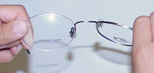
2                              1 Introduction to Shape Memory Alloys

(coupling of thermal with mechanical fields). Active materials can be fur-
ther subdivided into materials that exhibit direct or indirect coupling. Piezo-
ceramics, piezoelectric polymers, magnetostrictive ceramics, shape memory
alloys and magnetic shape memory alloys are examples of active materials
that exhibit a direct coupling. This implies that either the mechanical or
the non-mechanical field can serve as an input while the other as the out-
put. In contrast, for active materials such as electro-rheological fluids (ERF)
and magneto-rheological fluids (MRF), a change in the electric field or the
magnetic field can indirectly couple with the mechanical behavior through a
change in the viscosity of the fluid. This indirect, or one-way, coupling usually
lacks the reciprocity of the two-way coupling exhibited by active materials
that directly couple two fields.
    The suitability of an active material with direct coupling for actuation
applications depends on many factors. Two key design drivers are the actu-
ation energy density (available work output per unit volume) and the actu-
ation frequency of the material. An ideal active material would have both
a high actuation energy density and a high actuation frequency. Figures 1.1
and 1.2 compare the actuation energy densities and the actuation frequencies,
respectively, of some common active materials. The actuation energy density
is denoted in Fig. 1.1 by the dotted lines and is defined as the product of
the actuation strain (related to the stroke of an actuator) with the actuation
stress, assuming here that the active material is operating under constant
stress. The specific actuation energy density (work output per unit mass)

                               1000
                                                                                                             10
                                           Electrostrictive                                                   0
                                                                                                Shape Memory MJ/m 3
                                           ceramics
                                100                                                             Alloys (SMAs)
                                                              Magnetostrictive
                                                                                             Piezoelectric   10
      Actuation Stress (MPa)

                                                                    ceramics                                    MJ
                                                                                             polymers              /m     3

                                 10
                                                Piezoelectric
                                                  ceramics                                            Magnetic
                                                                                                      SMAs (MSMAs)
                                                                     Ionic electroactive
                                  1
                                                                          polymers
                                                                                           Shape Memory 100 k
                                                                                                             J/m
                                                                                           Polymers (SMPs)       3

                                 0.1
                                                                                                             10
                                                   10                   10                  1k                    kJ/
                                                      J/m                    0J               J/m                    m3
                                                          3                    /m 3               3

                                0.01
                                    0.01                0.1                      1                10                      100
                                                                    Actuation Strain (%)

Fig. 1.1. Actuation energy density diagram indicating typical ranges of actuation
stress, actuation strain, and the actuation energy densities of different active mate-
rials that exhibit direct coupling.
1.1 Introduction: Overview of Active Materials               3

                                                 104
                                               1.E+04

    Specific Actuation Energy Density (J/kg)
                                                                              Shape Memory Alloys (SMAs)
                                                 103
                                               1.E+03

                                                                                   Piezoelectric polymers

                                                 102
                                               1.E+02            Shape Memory Polymers (SMPs)

                                                                                           Magnetic SMAs (MSMAs)
                                                 101
                                               1.E+01                                      Electrostrictive ceramics
                                                                                                         Magnetostrictive ceramics

                                                 100
                                               1.E+00                              Piezoelectric ceramics
                                                        Ionic electroactive
                                                        polymers

                                                10-1
                                               1.E-01
                                                    10-1
                                                   1.E-01     100
                                                            1.E+00     101
                                                                     1.E+01     102
                                                                              1.E+02     103
                                                                                       1.E+03     104
                                                                                                1.E+04     105
                                                                                                         1.E+05     106
                                                                                                                  1.E+06     107
                                                                                                                           1.E+07
                                                                              Actuation Frequency (Hz)

Fig. 1.2. Actuation frequency diagram comparing the actuation frequency ranges
of different active materials that exhibit direct coupling.

for a specific active material can be calculated from Fig. 1.1 by dividing the
actuation energy density by the mass density.
    Shape Memory Alloys (SMAs) are a unique class of shape memory materi-
als with the ability to recover their shape when the temperature is increased.
An increase in temperature can result in shape recovery even under high
applied loads therefore resulting in high actuation energy densities as shown
in Fig. 1.1. In addition, under specific conditions, SMAs can absorb and dis-
sipate mechanical energy by undergoing a reversible hysteretic shape change
when subjected to applied mechanical cyclic loading. These unique charac-
teristics of SMAs have made them popular for sensing and actuation, impact
absorption and vibration damping applications. SMAs do, however, exhibit
low frequency response, as shown in Fig. 1.2. Higher actuation frequencies are
achievable for a class of SMAs called magnetic shape memory alloys, which
have recently been investigated.
    The application of SMAs spans a wide variety of industrial sectors such
as aerospace, automotive, biomedical, and oil exploration. Over the past few
decades, several key works have explored the microstructural mechanisms,
engineering effects, and applications of shape memory alloys, including the
experimental work of Jackson and coworkers [1], the application considera-
tions of Duerig and others [2], and the comprehensive summaries of Perkins,
Funakubo, and Otsuka and Wayman [3–5]. In the context of the current
textbook, this chapter will provide insights into the history of SMAs, their
properties, their microstructural behavior, and their varied industrial
applications.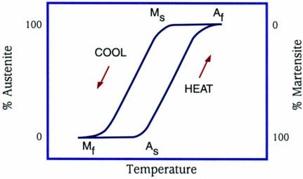
4      1 Introduction to Shape Memory Alloys

1.2 Shape Memory Alloys - A Brief History

The discovery of martensite in steels in the 1890s by Adolf Martens was
a major step toward the eventual discovery of shape memory alloys. The
martensitic transformation was perhaps the most widely studied metallur-
gical phenomenon during the early 1900s. The martensitic transformation,
as observed in the Fe-C system, was established as an irreversible process.
The concept of thermoelastic martensitic transformation, which explained the
reversible transformation of martensite, was introduced in 1949 by Kurdju-
mov and Khandros [6], based on experimental observations of the thermally
reversible martensitic structure in CuZn and CuAl alloys. By 1953, the occu-
rance of thermoelastic martensitic transformation was demonstrated in other
alloys such as InTl and CuZn.
    The reversible martensitic transformation and the alloys that exhibited
them remained unutilized until 1963. The breakthrough for engineering appli-
cations occurred with the discovery of NiTi by Buehler and coworkers while
investigating materials useful for heat shielding [7]. It was noticed that in
addition to its good mechanical properties, comparable to some common engi-
neering metals, the material also possessed a shape recovery capability. Fol-
lowing this observation, the term “NiTiNOL” was coined for this NiTi mate-
rial in honor of its discovery at the Naval Ordnance Laboratory (NOL). The
term Shape Memory Effect (SME) was given to the associated shape recovery
behavior. The discovery of Nitinol spearheaded active research interest into
SMAs. The effects of heat treatment, composition and microstructure were
widely investigated and began to be understood during this period [1].
    In 1965, studies [8] showed that the addition of a third alloying element
such as Co or Fe to the existing NiTi system caused a dramatic decrease in
the SMA transformation temperatures. The new alloys inspired the first com-
mercial SMA application, known as Cryofit, where SMA material was used
for pipe couplings in F-14 fighter aircraft [9, 10]. The transformation temper-
atures for Cryofit were so low that, to prevent actuation from occurring before
the assembly, the pipe couplings were transported in liquid nitrogen. Contin-
ued research to address this issue led to the development of the NiTiNb system
in 1989, which was easier to handle due to its larger temperature hysteresis,
and found widespread applications in battle damage repairs and in repairs
for nuclear reactors [11]. High Temperature SMAs (HTSMAs), such as TiPd,
TiPt and TiAu (with transformation temperatures greater than 100 ◦C), were
also developed as early as 1970 [12]. Meanwhile, Melton and Mercier [13],
while studying the fatigue properties of NiTi in 1978, showed that alloying
the material with Cu did not change the transformation temperatures con-
siderably, but narrowed the stress hysteresis. Later in 1999, Miyazaki showed
improved fatigue life for NiTiCu alloys [14]. The improved fatigue life and
the low cost associated with this material system made it suitable for a wide
variety of engineering applications.
1.3 Phenomenology of Phase Transformation in Shape Memory Alloys 5
Since the initial discovery of Nitinol in 1963, many commercial applica-
tions have been developed. During the 1970s, several uses of NiTi in biomedi-
cal applications appeared, but it wasn’t until the 1990s that NiTi stents made
their commercial breakthrough. By this time, SMAs had found additional
applications in air conditioning vents, electronic cable connectors, valves and
a variety of other products. In addition, over the last decade the demand
for actuation under high temperature operating conditions, driven by the
aerospace and oil industries, has revived a great deal of interest in the devel-
opment of HTSMAs. Finally, alloys that exhibit shape change characteristics
similar to SMAs but under the influence of a magnetic field have recently
been under investigation [15, 16]. The high actuation frequencies and the large
strains generated in Magnetic SMAs (MSMAs) have made these materials a
strong candidate for high frequency actuation devices.
1.3 Phenomenology of Phase Transformation in Shape
Memory Alloys
A metallurgical phase diagram for a metallic alloy is a schematic represen-
tation of the equilibrium conditions between distinct phases. Phase diagrams
consist of equilibrium lines or phase boundaries that separate different phases
from each other. For an alloy consisting of at least two elements, the concen-
tration becomes an important variable and is generally represented along the
abscissa axis. The other variable commonly used is the temperature, repre-
sented along the ordinate axis. A phase diagram can have different control
variables (stress, temperature, concentration, electric field etc.) within the
bounds of which the equilibrium phases can be represented. For an alloy at a
fixed composition (i.e. any vertical line parallel to the ordinate axis), the for-
mation and disassociation of phases with the change in temperature is shown.
Similarly, within the typical operating temperature range, SMAs have two
phases, each with a different crystal structure and therefore different proper-
ties. One is the high temperature phase called austenite (A) and the other is
the low temperature phase called martensite (M). Austenite (generally cubic)
has a different crystal structure from martensite (tetragonal, orthorhombic
or monoclinic). The transformation from one structure to the other does not
occur by diffusion of atoms, but rather by shear lattice distortion. Such a
transformation is known as martensitic transformation. Each martensitic crys-
tal formed can have a different orientation direction, called a variant. The
assembly of martensitic variants can exist in two forms: twinned martensite
(M t ), which is formed by a combination of “self-accommodated” martensitic
variants, and detwinned or reoriented martensite in which a specific variant is
dominant (M d ). The reversible phase transformation from austenite (parent
phase) to martensite (product phase) and vice versa forms the basis for the
unique behavior of SMAs.6 1 Introduction to Shape Memory Alloys
Upon cooling in the absence of an applied load, the crystal structure
changes from austenite to martensite. The phase transition from austenite to
martensite is termed the forward transformation. The transformation results
in the formation of several martensitic variants, up to 24 for NiTi. The arrange-
ment of variants occurs such that the average macroscopic shape change is
negligible, resulting in twinned martensite. When the material is heated from
the martensitic phase, the crystal structure transforms back to austenite, and
this transition is called reverse transformation, during which there is no asso-
ciated shape change.
A schematic of the crystal structures of twinned martensite and austenite
for an SMA and the transformation between them is shown in Fig. 1.3. There
are four characteristic temperatures associated with the phase transforma-
tion. During the forward transformation, austenite, under zero load, begins
to transform to twinned martensite at the martensitic start temperature (Ms )
and completes transformation to martensite at the martensitic finish temper-
ature (Mf ). At this stage, the transformation is complete and the material is
fully in the twinned martensitic phase. Similarly, during heating, the reverse
transformation initiates at the austenitic start temperature (As ) and the trans-
formation is completed at the austenitic finish temperature (Af ).
If a mechanical load is applied to the material in the twinned marten-
sitic phase (at low temperature), it is possible to detwin the martensite by
reorienting a certain number of variants (see Fig. 1.4). The detwinning pro-
cess results in a macroscopic shape change, where the deformed configuration
is retained when the load is released. A subsequent heating of the SMA to
Twinned M f Ms Austenite
Martensite
Twinned
As Af Austenite
Martensite
Fig. 1.3. Temperature-induced phase transformation of an SMA without mechani-
cal loading.1.3 Phenomenology of Phase Transformation in Shape Memory Alloys 7
Stress, σ
Detwinned Martensite
σf
σs
Twinned Martensite
Mf Ms As Af Temperature, T
Fig. 1.4. Schematic of the shape memory effect of an SMA showing the detwinning
of the material with an applied stress.
a temperature above Af will result in a reverse phase transformation (from
detwinned martensite to austenite) and will lead to complete shape recovery
(see Fig. 1.5). Cooling back to a temperature below Mf (forward transforma-
tion) leads to the formation of twinned martensite again with no associated
Stress, σ
Detwinned Martensite
σf
σs Austenite
Mf Ms As Af Temperature, T
Fig. 1.5. Schematic of the shape memory effect of an SMA showing the unloading
and subsequent heating to austenite under no load condition.8 1 Introduction to Shape Memory Alloys
shape change observed. The process described above is referred to as the Shape
Memory Effect (SME). The load applied must be sufficiently large to start the
detwinning process. The minimum stress required for detwinning initiation is
termed the detwinning start stress (σs ). Sufficiently high load levels will result
in complete detwinning of martensite where the corresponding stress level is
called the detwinning finish stress (σf ).
When the material is cooled with a mechanical load greater than σs applied
in the austenitic phase, the phase transformation will result in the direct
formation of detwinned martensite, producing a shape change. Reheating
the material will result in shape recovery while the load is still applied. A
schematic of the above-described loading path is shown in Fig. 1.6. Recog-
nizing that the forward and reverse transformations occur over a range of
temperatures (Ms to Mf , As to Af ) for a given SMA composition, we can
construct transformation regions in the stress-temperature space. The trans-
formation temperatures strongly depend on the magnitude of the applied load,
with higher values of applied load leading to higher transformation tempera-
tures. As a consequence, the transformation regions representing the A→M d
and M d →A transformations have a positive slope in stress-temperature space.
Irrespective of the nature of applied load (tension or compression), the trans-
formation temperatures increase with an increase in the magnitude of the
load. Under an applied uniaxial tensile load with a corresponding stress, σ, the
new transformation temperatures are represented as Mfσ , Msσ , Aσs and Aσf for
martensitic finish, martensitic start, austenitic start and the austenitic finish
temperatures, respectively. It should be noted that σ refers to the magnitude
Stress, σ
Detwinned Martensite
M σf M sσ
Asσ Aσf
σf
σs Austenite
Mf Ms As Af Temperature, T
Fig. 1.6. Temperature-induced phase transformation in the presence of applied
load.1.3 Phenomenology of Phase Transformation in Shape Memory Alloys 9
of a uniaxial stress state or an appropriate scalar measure for a multiaxial
stress state, as will be explained in Chapter 3.
In addition to thermally induced phase transformation, transformation can
also be induced by applying a sufficiently high mechanical load to the material
in the austenitic phase. The result of this load is fully detwinned martensite
created from austenite. If the temperature of the material is above Af , a com-
plete shape recovery is observed upon unloading to austenite. This material
behavior is called the pseudoelastic effect. A loading path demonstrating the
pseudoelastic effect is shown schematically in Fig. 1.7, while the associated
macroscopic shape change due to the applied load is captured in the resulting
stress-strain diagram, as shown schematically in Fig. 1.8. The stress levels
at which the martensite transformation initiates and completes are denoted
by σ M s and σ M f , respectively. Similarly, as the SMA is unloaded, the stress
levels at which the material initiates and completes its reverse transforma-
tion to austenite are denoted by σ As and σ Af , respectively. If the material in
the austenitic phase is tested above the Ms temperature, but below the Af
temperature, only partial shape recovery is observed.
Figure 1.9 shows a schematic representation of the different phases of
the SMA, which include the austenitic phase and both the twinned (self-
accommodated) and detwinned martensite, along with the transition zones,
in a stress-temperature diagram. Such a diagram, illustrating the different
phases in a stress-temperature space for a given SMA with fixed composition,
is called the phase diagram. Note that the phase diagram of Fig. 1.9 is a special
case of the metallurgical phase diagram introduced in the beginning of Sec-
tion 1.3, which involves composition as another variable. Construction of the
Stress, σ
Detwinned Martensite
σ Mf
σ Ms
σf
σ As
σs Austenite
σ Af
Mf Ms As Af Temperature, T
Fig. 1.7. A pseudoelastic loading path.10 1 Introduction to Shape Memory Alloys
Stress, σ
Detwinned Martensite
σ Mf
σ Ms
σ As
σ Af
Austenite
Strain, ε
Fig. 1.8. Schematic of a pseudoelastic stress-strain diagram.
Stress, σ
Detwinned Martensite
d
A to M
σf
t d d
M to M M to A
σs Austenite
Twinned Martensite
Mf Ms As Af Temperature, T
Fig. 1.9. Schematic of a stress-temperature phase diagram for an SMA.
phase diagram involves the interpretation of the SMA material response sub-
jected to various thermomechanical loading paths resulting in shape memory
thermal actuation under load and pseudoelastic behavior. In the following sec-
tions, the two important characteristics of SMAs, namely the shape memory
effect and pseudoelasticity, will be discussed in more detail.1.4 Shape Memory Effect 11
1.4 Shape Memory Effect
An SMA exhibits the shape memory effect (SME) when it is deformed while
in the twinned martensitic phase and then unloaded while at a temperature
below As . When it is subsequently heated above Af , the SMA will regain
its original shape by transforming back into the parent austenitic phase. The
nature of the SME can be better understood by following the thermomechan-
ical loading path in a combined stress-strain-temperature space as shown in
Fig. 1.10. Figure 1.10 represents experimental data for a typical NiTi speci-
men tested under uniaxial loading. The stress σ is the uniaxial stress on the
specimen due to an applied load. The corresponding strain ε is the change in
the length of the specimen along the direction of applied load, normalized by
the original length.
Starting from the parent phase (point A in Fig. 1.10), the stress-free cool-
ing of austenite below the forward transformation temperatures (Ms and Mf )
results in the formation of twinned martensite (point B). When the twinned
martensite is subjected to an applied stress that exceeds the start stress level
(σs ), the reorientation process is initiated, resulting in the growth of cer-
tain favorably oriented martensitic variants that grow at the expense of other
less favorable variants. The stress level for reorientation of the variants is far
lower than the permanent plastic yield stress of martensite. The detwinning
process is completed at a stress level, σf , that is characterized by the end of
σ (MPa)
Detwinned
800 Martensite
C
600
σf
σs 400
Detwinning
Twinned 200
ε
Martensite
2% 4% D 6%
B
cooling As Detwinned
Austenite E
Af 50 Martensite
F
A 100
T (°C)
Fig. 1.10. Stress-strain-temperature data exhibiting the shape memory effect for a
typical NiTi SMA.12 1 Introduction to Shape Memory Alloys
the plateau in the σ-ε diagram in Fig. 1.10. The material is then elastically
unloaded from C to D and the detwinned martensitic state is retained. Upon
heating in the absence of stress, the reverse transformation initiates as the
temperature reaches As , (at E) and is completed at temperature Af (point
F), above which only the parent austenitic phase exists. In the absence of
permanent plastic strain generated during detwinning, the original shape of
the SMA is regained (indicated by A). The strain recovered due to the phase
transformation from detwinned martensite to austenite is termed as the trans-
formation strain (εt ). Subsequent cooling to martensite will again result in the
formation of self-accommodated twinned martensitic variants with no asso-
ciated shape change, and the whole cycle of the SME can be repeated. The
above described phenomenon is called one-way shape memory effect, or sim-
ply SME, because the shape recovery is achieved only during heating after
the material has been detwinned by an applied mechanical load.
Example 1.1. In order to review the SME, let us consider an SMA
wire whose behavioral characteristics are represented by the stress-strain-
temperature diagram shown in Fig. 1.10. The SME of the wire is used for
a one time actuation application. The wire, held at a temperature below the
Mf (twinned martensitic state), is stretched along the axial direction. Under
the applied loading, the material exhibits an elastic behavior and continues
to elastically deform as the stress is increased. When the stress due to the
applied loading reaches approximately 150MPa, the SMA wire begins to elon-
gate significantly with a small increment in the stress level. This point marks
the beginning of the martensitic detwinning in the wire. The detwinning con-
tinues until the total strain reaches approximately 4% and the entire wire
has detwinned. At this point, the wire begins to stiffen again as the stress is
increased. The end of the detwinning process is marked by the change in the
slope during loading. The detwinned wire elastically unloads as the stress is
released and the strain induced due to the detwinning is not recovered. This
detwinned wire is then attached on the structure for the actuation application.
During the actuation process, the wire is heated using a thermal source such
as resistive heating. As the temperature of the wire increases, the wire ini-
tially undergoes thermal expansion. However, as the temperature reaches the
austenitic start temperature of approximately 30 ◦C, the detwinned marten-
site in the material begins transformation into austenite. This results in the
contraction (i.e., actuation) of the SMA. As the temperature reaches a value
above 70 ◦C, the transformation (actuation) is complete and the wire is in the
austenitic state. The exact austenitic finish temperature will depend on the
stress of the SMA wire during the reverse transformation. Subsequent cool-
ing returns the wire to the twinned state in the absence of a recovery stress
applied by the structure on which the SMA is attached. The wire would then
have to be detwinned for the next actuation cycle unless the structure can
provide sufficient stress for detwinning upon cooling.1.5 Pseudoelasticity 13
1.5 Pseudoelasticity
The pseudoelastic behavior of SMAs is associated with stress-induced trans-
formation, which leads to strain generation during loading and subsequent
strain recovery upon unloading at temperatures above Af . A pseudoelastic
thermomechanical loading path generally starts at a sufficiently high temper-
ature where stable austenite exists, then develops under an applied load to
a state at which detwinned martensite is stable, and finally returns to the
austenitic phase when returned to zero stress state. An example of this path
(a → b → c → d → e → a) is shown in Fig. 1.11 as path 1. Most commonly,
a pseudoelastic test is performed at a nominally constant temperature above
Af . The loading path for such a test is shown as path 2 in Fig. 1.11.
To illustrate the pseudoelastic behavior in greater detail, let us consider
the thermomechanical loading path (A → B → C → D → E → F → A)
in Fig. 1.11, which starts at zero stress at a temperature above Af . The
corresponding σ-ε experimental data for the loading path is shown in Fig. 1.12.
When a mechanical load is applied, the parent phase (austenite) undergoes
elastic loading (A → B). At a specific load level, the loading path intersects the
surface for initiation of martensitic transformation on the phase diagram. This
marks the stress level (σ M s ) for the onset of transformation into martensite.
Note that the stress-induced transformation from austenite to martensite is
accompanied by the generation of large inelastic strains as shown in the stress-
strain diagram of Fig. 1.12. The transformation proceeds (B → C), to the
stress level (σ M f ) where the loading path intersects the Mf transformation
surface, indicating the end of the transformation.
D
Path 2
Stress, σ
σ Mf
C
Detwinned Martensite
σ Ms B
c
Path 1
b
σ As E
Austenite
d
σ Af F
e
a A
Mf Ms As Af Temperature, T
Fig. 1.11. Phase diagram and two possible pseudoelastic loading paths.14 1 Introduction to Shape Memory Alloys
Fig. 1.12. A typical SMA pseudoelastic loading cycle.
The completion of martensitic transformation is indicated by a distinct
change in slope on the σ-ε curve, which is associated with the elastic load-
ing of the martensitic phase. A subsequent increase in the stress causes no
further transformation and only the elastic deformation of detwinned marten-
site occurs (C → D). When the stress is released gradually by unloading,
the martensite elastically unloads along the path (D → E). At point E, the
unloading path intersects the austenitic start surface (at σ As ), which causes
the martensite to revert to austenite. The process is accompanied by the
recovery of the strain due to phase transformation at the end of unloading.
The end of the transformation back into austenite is denoted by the point at
which the σ-ε unloading curve rejoins the elastic region of austenite (point
F corresponding to stress σ Af ). The material then elastically unloads to A.
The forward and reverse phase transformation during a complete pseudoelas-
tic cycle results in a hysteresis, which, in the σ-ε space, represents the energy
dissipated in the transformation cycle. The transformation stress levels and
the size of the hysteresis vary depending on the SMA material and testing
conditions.
The detwinned martensite that forms from austenite as a result of the
applied stress during Path 1 or 2 in Fig. 1.11 is one form of stress-induced
martensite (SIM). SIM, in general, is martensite that forms from austenite in
the presence of stress. There are many thermomechanical loading paths that
can result in the formation of SIM.1.6 Cyclic Behavior of SMAs 15
Generally, the term pseudoelasticity describes both superelastic behavior
and so-called rubber-like behavior [5]. The reversible phase transformation
(described in the previous paragraph) caused by a thermomechanical load-
ing path is strictly called the superelastic behavior. The rubber-like effect is
an exclusive behavior of the martensite phase only and occurs due to the
reversible reorientation of martensite. In some cases, aging the martensitic
phase can enable the reversal of the martensitic detwinning process upon
unloading at temperatures below Mf . The resulting σ-ε curve is similar to
the superelastic curve, and this phenomenon is called the rubber-like effect to
emphasize the similarities with the nonlinear elastic behavior of rubber. In
SMAs exhibiting the rubber-like effect, the stress required to detwin marten-
site is very small compared to σ M s . We will not consider the rubber-like effect
any further, and the term pseudoelasticity will refer to the superelastic behav-
ior of SMAs only.
1.6 Cyclic Behavior of SMAs
We have studied the one-way SME behavior in SMAs. Sometimes an SMA
can exhibit repeatable shape changes under no applied mechanical load when
subjected to a cyclic thermal load. This behavior is termed two-way shape
memory effect (TWSME). The TWSME can be observed in a SMA mate-
rial which has undergone repeated thermomechanical cycling along a specific
loading path (training). Repetition along a loading path for a large number of
cycles can induce changes in the microstructure, which causes macroscopically
observable permanent changes in the material behavior.
Training an SMA refers to a process of repeatedly loading the material
following a cyclic thermomechanical loading path until the hysteretic response
of the material stabilizes and the inelastic strain saturates. Let us consider the
case of cyclic thermal loading of an SMA specimen under a constant applied
stress (Fig. 1.13). During the first thermal cycle, only a partial recovery of
the strain generated during cooling is observed upon heating with some per-
manent (irrecoverable or plastic) strain generated during the cycle. A small,
permanent strain remains after each thermal cycle is completed. The addi-
tional permanent strain associated with each consecutive cycle begins to grad-
ually decrease until it practically ceases to further accumulate (Fig. 1.13). A
similar behavior can be noticed in the case of mechanically cycling an SMA
repeatedly in its pseudoelastic regime, until saturation takes place (Fig. 1.14).
The TWSME behavior can also be achieved by adopting different training
sequences [17, 18]. A more recent technique that leads to TWSME deals with
aging the material under stress in the martensitic state [19].
TWSME is a result of defects introduced during training. These perma-
nent defects create a residual internal stress state, thereby facilitating the
formation of preferred martensitic variants when the SMA is cooled in the16 1 Introduction to Shape Memory Alloys
10%
σ = 150 MPa
8%
Final cycle
6%
Strain
4%
Initial cycle
2%
0%
-10 0 10 20 30 40 50 60
Temperature (°.C)
Fig. 1.13. Thermal cyclic loading (50 cycles) of a NiTi shape memory alloy wire
under constant load of 150 MPa [18].
Fig. 1.14. Pseudoelastic response of an as-received NiTi wire with Af = 65 ◦C, tested
at a temperature of 70 ◦C. Also shown is the stabilized pseudoelastic hysteresis loop
after 20 cycles.Shape Memory Alloys (SMA)
Marek Novotny
Email: novotny@ac.tut.fi
Juha Kilpi
Abstract
This report introduces Shape Memory Alloys, describes properties of SMA as an actuator
and introduces some available commercial SMA actuator products.
Keywords: Shape Memory Alloy, active materials, actuator, microsystem technology
1. Introduction
This section presents brief history of SMA actuators. Next in Section 1.2, the basic
operation principle of SMA is given. Shape setting in NiTi alloys is discussed. The section
ends with an introduction of a two-way Shape memory effect and superelasticity.
1.1 Brief history of SMA [1]
A Swedish physicist Arne Olander discovered “the Shape Memory Effect” (SME) in gold-
cadmium (AuCd) alloy in 1932. The alloy could be deformed when cool and then heated to
return to original “remembered” shape. The metal alloys with SME are called “Shape
Memory Alloys” (SMA). In 1958, SME was demonstrated at the Brussels World’s Fair,
where the SME was used to cyclically lift a load mass. Researchers of U.S. Naval
Ordnance Laboratory found SME in nickel-titanium (NiTi) alloy in 1961 by accident,
while studying the heat and corrosion resistance of NiTi. Today, the NiTi alloys are
commonly referred to as “Nitinol”, for NiTi Naval Ordnance Laboratory.
The benefits of NiTi alloys, such as lower costs, smaller dangers (from health standpoint)
and easier manufacturing and machining methods refreshed the interest in SME and its
applications. In 1970’s, commercial products began to emerge. First devices were static,
taking advantage of a single dimensional change, for example fasteners, couplings and
electrical connectors. Then, SMA devices started to perform dynamic tasks as actuators.
Ambient temperature-controlled valves and clutches were the first applications, later
actuators with resistive heating and thus electrical control were proposed to be used in
micro-robotics, for example. More sophisticated devices are studied continuously, for
example [2, 3, 4].
1.2 Principle of operation [1]
Shape Memory Alloys, for example Ag-Cd, Au-Cd, Cu-Al-Ni, Cu-Sn, Cu-Zn-(X), In-Ti,
Ni-Al, Ni-Ti, Fe-Pt, Mn-Cu and Fe-Mn-Si alloys, are a group of metallic materials having
ability to return to a previously defined shape when subjected to appropriate thermal
procedure.Shape Memory Alloys, Introduction
The SME occurs due to a temperature and stress dependent shift in the material’s
crystalline structure between two different phases, martensite (low temperature phase) and
austenite (high temperature phase). The temperature, where the phase transformation
occurs, is called the transformation temperature. Figure 1 is a simplified representation of
material’s crystalline arrangement during different phases.
Figure 1: Crystalline arrangement of SMA in different phases.
In austenite phase, the structure of the material is symmetrical; each “grain” of material is
a cube with right angles (a). When the alloy cools, it forms the martensite phase and
collapses to a structure with different shape (b). If an external stress is applied, the alloy
will yield and deform to an alternate state (c). Now, if the alloy is heated again above the
transformation temperature, the austenite phase will be formed and the structure of the
material returns to the original “cubic” form (a), generating force/stress.
An example of an SMA wire is represented in Figure 2. If the wire is below the
transformation temperature (and therefore in the martensite form), it can be stretched with
an external stress. Now, if the wire is heated to austenite phase, it will generate force/stress
and recover the original, shorter, shape.
Also, hysteresis and non-linear behaviour are seen from Figure 2. The change in the SMA
crystalline structure is not thermodynamically reversible process due to internal frictions
and creation of structural defects. When heated, SMA follows the upper curve, As is the
temperature, where austenite phase starts to form and in Af the material is 100 % austenite.
When the alloy cools, it follows the lower curve: Ms is the temperature, where martensite
starts to form and in Mf the alloy is 100 % martensite.
2Shape Memory Alloys, Introduction
Figure 2: Contraction of an SMA wire as a function of temperature.
1.3 Shape setting in NiTi alloys [5]
The Shape Memory Effect must be “programmed” into the SMA alloys with an
appropriate thermal procedure. Basically the procedure is simple; the alloy is formed into
desired austenite form and heated into a specific temperature. The temperature and the
duration of the heating depend on the alloy and the required properties.
For a NiTi alloy, a temperature of 400 °C and heating duration of 1…2 minutes can be
sufficient, but generally 500 °C and over 5 minutes are used. Higher heat treatment times
and temperatures will increase the actuation temperature of the element and often give a
sharper thermal response, but may reduce the maximum output force.
Although straightforward procedure, the parameters for the heat treatment are critical and
often require experimental determination before the requirements can be met.
1.4 Two-way Shape Memory Effect [6]
The ability of SMA to recover a specific shape upon heating and then return to an alternate
shape when cooled (below the transformation temperature) is known as two-way shape
memory. However, there are limitations that reduce the usability of the two-way effect,
such as smaller strains (2 %), extremely low cooling transformation forces and unknown
long-term fatigue and stability. Even slight overheating removes the SME in two-way
devices.
Setting shapes in two-way SMAs is a more complex procedure than the one used with one-
way SMAs.
1.5 Superelasticity [7]
SMA also shows a superelastic behaviour if deformed at a temperature which is slightly
above their transformation temperatures. This effect is caused by the stress-induced
formation of some martensite above its normal temperature. Because it has been formed
3Shape Memory Alloys, Introduction
above its normal temperature, the martensite reverts immediately to undeformed austenite
as soon as the stress is removed. This process provides a very springy, "rubberlike"
elasticity in these alloys.
Because the superelastic behaviour is not usable in actuators, it is not described in details.
As an example, the superelastic alloys are used in eyeglass frames. Figure 3 presents
DuraFLEX eyeglasses.
Figure 3: DuraFLEX eyeglasses.
2. SMA as an actuator
The properties of SMA as an actuator can be divided into advantages and disadvantages
rather clearly. On the other hand some properties must be categorized according to a
specific application. Also the properties vary between different alloy compositions. The
properties are discussed in the following Sections, from 3.1 to 3.8. The focus is on the NiTi
alloy, because this alloy is the most widely used and considered as the most suitable alloy
in engineering applications [1].
2.1 Force and Deformations
The greatest advantage of the SMA material is the availability of a large force from very
small element dimensions and weight. Table 1 shows some properties of commercially
available “Flexinol” NiTi alloy SMA wires, manufactured by DYNALLOY, Inc. [9]. It can
be seen that a ≈0.38 mm (0.015”) diameter wire can generate a pull force of ≈2000 g
(≈19.5 N), for example. This gives about 170 N/mm2 stress (force per cross-sectional
area).
Table 1: Properties of Flexinol wire (NiTi alloy).
Diameter Resistance Maximum Approximate* Contraction* Off Time Off Time
Size (Inches) (Ohms/Inch) Pull Current at Time 70° C 90° C
Force Room (seconds) Wire** Wire**
(gms.) Temperature (seconds) (seconds)
(mA)
0.0015 21.0 17 30 1 0.25 0.09
0.002 12.0 35 50 1 0.3 0.1
0.003 5.0 80 100 1 0.5 0.2
0.004 3.0 150 180 1 0.8 0.4
0.005 1.8 230 250 1 1.6 0.9
0.006 1.3 330 400 1 2.0 1.2
4Shape Memory Alloys, Introduction
0.008 0.8 590 610 1 3.5 2.2
0.010 0.5 930 1000 1 5.5 3.5
0.012 0.33 1250 1750 1 8.0 6.0
0.015 0.2 2000 2750 1 13.0 10.0
Theoretically, a force generated by any shape/size SMA element can be calculated from
maximum stress generated by the SMA material.
SMA alloys provide a large deformation, compared to other active materials. Maximum
deformation is approximately 7…8 % for NiTi element. The effects of cycling (repeated
use) to maximum deformation are described is Section 2.5. Table 2 shows some properties
of different alloys, manufactured by Advanced Materials and Technologies (AMT). It can
be seen that the normal recommended deformation is from 3.2 % (NiTi) to only 0.8 % (Cu-
Zn-Al).
Table 2: Properties of different SMA alloys (by AMT).
ITEM Ni-Ti Cu-Cu-Zn-Al Cu-Al-Ni
Melting point (°C) 1250 1020 1050
Density (Kg/m³) 6450 7900 7150
Electrical Resistivity (Ω *m*10E-6) 0.5-1.1 0.07-0.12 0.1-0.14
Thermal Conductivity, RT (W/m*K) 10-18 120 75
Thermal Expansion Coeff. (10E-6/K) 6.6-10 17 17
Specific Heat (J/Kg*K) 490 390 440
Transformation Enthalpy (J/Kg) 28,000 7,000 9,000
E-modulus (GPa) 95 70-100 80-100
UTS, mart. MPa) 800-1000 800-900 1000
Elongation at Fracture, mart. (%) 30-50 15 8-10
Fatigue Strength N=10E+6 (MPa) 350 270 350
Grain size (m*10E-6) 20-100 50-150 30-100
Transformation Temp. Range (°C.) -100 to +110 -200 to +110 -150 to +200
Hysteresis (K) 30 15 20
Max one-way memory (%) 7 4 6
Normal two-way memory (%) 3.2 .8 1
Normal working Stress (MPa) 100-130 40 70
Normal number of thermal cycles +100 000 +10 000 +5 000
Max. Overheating Temp. (°C) 400 150 300
Damping capacity (SDC %) 20 85 20
Corrosion Resistance Excellent Fair Good
Biological Compatibility Excellent Bad Bad
2.2 One-way force
As an actuator, the SMA element can only provide force/displacement in one direction.
For example, a wire that compresses when heated does not expand without external force,
when the alloy cools down. This is one disadvantage of the SMA actuators. A bias (return)
5Shape Memory Alloys, Introduction
mechanism must be used, if actuator has to be returned to the original (cold) shape after
the heating phase. Figure 4 shows possibilities for generating the bias force.
Figure 4: Bias mechanisms in SMA actuators.
The bias mechanism is usually implemented with a conventional spring, for example with
a standard steel coil spring. The bias mechanism requires space, increases the weight of the
actuator and the mechanical design becomes more complex. It must also be noted that the
net output force decreases, because the force of the bias mechanism opposes the force of
the SMA element.
If possible, a load force can be used as bias force. In Figure 4, gravity is used as an
example of a load force as a bias force. The load force has to be large enough at all times,
otherwise the actuator remains in the austenite position, even if heating is deactivated.
Another method to generate the bias force is to use an actuator that has SMA elements
operating in both directions of movement. This is referred to as “an antagonistic SMA”.
This provides output force to both directions, but the heating and cooling of opposing
elements must be arranged properly. For example, if one element has been heated and then
immediately after this an opposing element is heated, the first element resists the
movement of the second, before the first element cools down enough. Also, if the elements
are very close to each other, the heat transfer between elements can generate undesired
forces.
There have been studies of “two-way” Shape Memory Effect that could provide force in
both heating and cooling phases. This would remove the need for a bias mechanism. Due
to restrictions of two-way memory (Section 1.4), it is recommended that one-way devices
with return (bias) mechanism are preferred instead of two-way devices [7].
2.3 Cycling effects
Cycling (repeated use) affects the properties of the SMA. This must be considered when
actuators are designed for a repeated/continuous use. Cycling causes the maximum
available deformation, force and hysteresis to decrease, while the transformation
temperatures increase gradually.
The reduction in the maximum strain and output force must be taken into account when
actuators are designed. For NiTi alloys, only 2…3 % strain and stress level of 100...150
MPa are available after 100 000 cycles.
2.4 Hysteresis and non-linearity
SMA materials have a non-linear behaviour with a large hysteresis, as can be seen in
Figure 2. This is a major setback when actuators are designed. If the movement of the
6Shape Memory Alloys, Introduction
actuator has to be controlled, for example the displacement of an actuator generating linear
movement, hysteresis and non-linearity cause difficulties. Therefore, many SMA actuators
are “on/off” controlled, having only two positions of movement. This is easily obtained
with continuous heating to maintain totally austenite phase or continuous cooling to obtain
totally martensite phase.
Amount of hysteresis depends on the alloy composition, as can be seen in Table 2. Typical
values for hysteresis in NiTi alloys are 25…50 °C [10].
In some applications hysteresis can be beneficial, as in a temperature control thermostat.
When temperature raises enough, the SMA deactivates heating or activates cooling.
Hysteresis prevents immediate “on/off” toggling of heaters/coolers and creates a proper
thermostat function.
2.5 Temperature control of SMA element
Because the SMA effect is based on the temperature changes of the SMA material, the
SMA actuators must have a method for controlling the temperature of the SMA element.
Heating and cooling solutions and their properties are described in following Sections,
2.6.1 to 2.6.3.
2.5.1 Heating of SMA element
The heating of the SMA element can be accomplished with several methods by an electric
current fed through the alloy, a separate heater element or heating with ambient material.
These provide convenient and flexible possibilities for controlling the temperature of the
alloy.
The heating with current (“Joule heating”) gives effective control over the temperature and
therefore force and displacement. Although the concept is simple, it has two
disadvantages. First, the resistance of the SMA is small (metal alloy). This causes the
requirement for a large heating current, Table 1 shows some currents for different
“Flexinol” wire sizes, for example 2.75 A is needed for a 0.38 mm wire. A current supply
able to provide enough current increases the overall size and costs of the actuator system.
Secondly, the heating current must flow through the SMA element, not through other
conductive parts near or in contact with the SMA element. Therefore, the SMA must be
electrically isolated from the surrounding environment. This causes special requirements
for the components of the actuators.
Both DC and AC current can be used in heating. If AC is used, the frequency must be high
enough to prevent oscillation in the SMA element temperature, which would cause
oscillation of the actuator displacement and force. With AC, the heating effect depends on
the root-mean-square (RMS) value of the current.
A separate heater element can overcome the difficulties of large currents used with the
current heating method. A resistive heater element can provide enough power with smaller
currents due to possibility to use larger voltage. On the other hand, a separate heater
requires more components and additional space around the SMA element, also the total
weight of the actuator increases. A heater element increases the cooling cycle time
(Section 2.6.2) due to additional heated mass.
If the ambient material is used for heating (without any active elements), the SMA element
operates according to the ambient temperature. This gives a possibility to use SMA as an
ambient temperature controlled actuator, for example a heating thermostat controlling the
7Shape Memory Alloys, Introduction
heating or cooling of ambient material. This is a very effective method, because in this
case the SMA operates as an integrated actuator and a sensor, without any electric
connectors.
2.5.2 Cooling of SMA element
The cooling of SMA element can be done with ambient material, requiring that the
ambient temperature is lower than the transformation temperature range of the SMA
element.
This method is useful, if the speed/band-width requirements are not critical. When the
ambient temperature is close to the transformation temperatures, the cooling is slow. On
the other hand, smaller heating current is needed to increase temperature to achieve the
austenite phase. If the ambient temperature is much lower than the transformation
temperatures, the cooling is quicker, but larger heating currents are needed.
Active cooling elements are needed if it is necessary to lower the temperature quickly or
the ambient temperature is too high to achieve temperatures low enough to achieve
martensite phase.
Forced convection cooling (with a fan, for example) is a relatively easy method for active
cooling. Also cooling with moving liquid can be used in some applications. However, it
must be noted that more powerful cooling system increases the required heating current, if
the cooling is active continuously.
2.5.3 Peltier elements, integrated heating and cooling
One method for achieving active heating and cooling capacity is to use Peltier elements.
These elements can heat or cool the SMA element, depending on the polarity of the
voltage fed into the Peltier element. This method is useful, if both heating and cooling
cycles must be quick. On the other hand also Peltier elements require space and create
additional weight to the actuator entity.
2.6 Raw material
The raw material for SMA elements is inexpensive, especially NiTi alloy having only two
component metals. It must be noted that the actual price for a complete SMA actuator
depends on the other components and devices needed to create a proper actuator. Current
supplies, Peltier elements, required measurements/sensors and other components that must
be used set the total price, not the SMA material/element.
The corrosion resistance of NiTi alloys is excellent (comparable to stainless steels),
providing a possibility to use SMA in environment with high humidity or even water.
Also the biological compatibility of NiTi is excellent.
3. Shape Memory Alloy device examples
There are quite a few devices utilizing SMA commercially available. Some of these are
described in Sections 3.1 to 3.6 to give a brief overview of possibilities.
Raw material for SMA elements is available from several companies, as well as ready-to-
use (heat treated) SMA wires, expanding and contracting springs, and superelastic tubes. A
list of manufacturers supplying SMA materials, elements or actuators is given in Section
3.7.
8Shape Memory Alloys
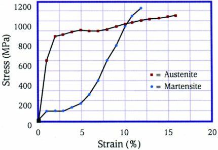
Shape Memory Alloys (SMAs) refer to a STRESS-STRAIN CHARACTERISTICS
group of materials which have the ability
to return to a predetermined shape when
heated. The shape memory effect is
caused by a temperature dependent crystal
structure. When an SMA is below its
phase transformation temperature, it
possesses a low yield strength
crystallography referred to as Martensite
(see Stress-Strain figure). While in this
state, the material can be deformed into
other shapes with relatively little force.
The new shape is retained provided the
material is kept below its transformation
temperature. When heated above this
temperature, the material reverts to its
parent structure known as Austenite
causing it to return to its original shape
(see Phase Transformation figure). This PHASE TRANSFORMATION
phenomenon can be harnessed to provide
a unique and powerful actuator.
The most widely used shape memory
material is an alloy of Nickel and
Titanium called Nitinol. This particular
alloy has excellent electrical and
mechanical properties, long fatigue life,
and high corrosion resistance. As an
actuator, it is capable of up to 5% strain
and 50,000 psi recovery stress, resulting
in ~1 Joule/gm of work output. Nitinol is
readily available in the form of wire, rod,
and bar stock with transformation
temperature in the range of -100º to +100º
Celsius. More recently applications in Properties of Nitinol
Micro-Electro-Mechanical-Systems Density 6.45 gm/cm3 0.23 lb/in3
(MEMS) have led to the development of Thermal Conductivity 10 W/moK 5.78 Btu/hr ftoF
Nitinol in the form of sputter deposited
thin film. Specific Heat 322 j/kgoK 0.08 Btu/lboF
Latent Heat 24,200 J/kg 10.4 Btu/lb
For more information about Shape
Ultimate Tensile Strength 750-960 Mpa 110-140 ksi
Memory Alloy and its applications,
contact TiNi Aerospace at the address Elongation to Failure 15.5% 15.5 %
below. Yield Strength (Austenite) 560 Mpa 80 ksi
Young's Modulus (Austenite) 75 Gpa 11 Mpsi
Yield Strength (Martensite) 100 Mpa 15 ksi
2235 Polvorosa Ave, San Leandro, CA 94577 Tel: (510) 483-2564 Fax: (510) 483-2032
E-mail: marketing@tiniaerospace.com Web: www.tiniaerospace.comYou can also read