STRAIN INDUCED ANISOTROPIC MAGNETIC BEHAVIOUR AND EXCHANGE COUPLING EFFECT IN FE-SMCO5 PERMANENT MAGNETS GENERATED BY HIGH PRESSURE TORSION
←
→
Page content transcription
If your browser does not render page correctly, please read the page content below
S TRAIN I NDUCED A NISOTROPIC M AGNETIC B EHAVIOUR AND
                                                       E XCHANGE C OUPLING E FFECT IN F E -S M C O5 P ERMANENT
                                                          M AGNETS G ENERATED BY H IGH P RESSURE T ORSION

                                                                                                    A P REPRINT
arXiv:2101.03900v2 [cond-mat.mtrl-sci] 19 Jan 2021

                                                                                                 Lukas Weissitsch
                                                                    Erich Schmid Institute of Materials Science, Austrian Academy of Sciences
                                                                                               8700 Leoben, Austria
                                                                                        lukas.weissitsch@oeaw.ac.at

                                                                                                 Martin Stückler
                                                                    Erich Schmid Institute of Materials Science, Austrian Academy of Sciences
                                                                                               8700 Leoben, Austria

                                                                                                 Stefan Wurster
                                                                    Erich Schmid Institute of Materials Science, Austrian Academy of Sciences
                                                                                               8700 Leoben, Austria

                                                                         Peter Knoll                                           Heinz Krenn
                                                                     Institute of Physics                                   Institute of Physics
                                                           University of Graz, 8010 Graz, Austria                 University of Graz, 8010 Graz, Austria

                                                                                                Reinhard Pippan
                                                                    Erich Schmid Institute of Materials Science, Austrian Academy of Sciences
                                                                                               8700 Leoben, Austria

                                                                                                Andrea Bachmaier
                                                                    Erich Schmid Institute of Materials Science, Austrian Academy of Sciences
                                                                                               8700 Leoben, Austria

                                                                                                 January 20, 2021

                                                                                                   A BSTRACT
                                                        High-pressure torsion (HPT), a technique of severe plastic deformation (SPD), is shown as a promising
                                                        processing method for exchange-spring magnetic materials in bulk form. Powder mixtures of Fe and
                                                        SmCo5 are consolidated and deformed by HPT exhibiting sample dimensions of several millimetres,
                                                        being essential for bulky magnetic applications. The structural evolution during HPT deformation of
                                                        Fe-SmCo5 compounds at room- and elevated- temperatures of chemical compositions consisting of 87,
                                                        47, 24 and 10 wt.% Fe is studied and microstructurally analysed. Electron microscopy and synchrotron
                                                        X-ray diffraction reveal a dual-phase nanostructured composite for the as-deformed samples with
                                                        grain refinement after HPT deformation. SQUID magnetometry measurements show hysteresis
                                                        curves of an exchange coupled nanocomposite at room temperature, while for low temperatures a
                                                        decoupling of Fe and SmCo5 is observed. Furthermore, exchange interactions between the hard- and
                                                        soft-magnetic phase can explain a shift of the hysteresis curve. Strong emphasis is devoted to the
                                                        correlation between the magnetic properties and the evolving nano-structure during HPT deformation,
                                                        which is conducted for a 1:1 composition ratio of Fe to SmCo5 . SQUID magnetometry measurements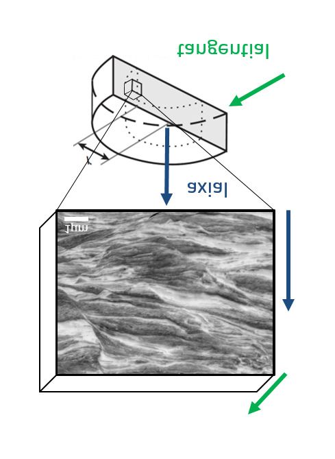
Strain Induced Anisotropic Magnetic Behaviour and Exchange Coupling Effect in Fe-SmCo5 Permanent Magnets
                                         Generated by High Pressure Torsion                        A P REPRINT

          show an increasing saturation magnetisation for increasing strain γ and a maximum of the coercive
          field strength at a shear strain of γ = 75.

Keywords: nanostructured composite; Fe-SmCo5 heterostructure; exchange coupled; spring magnet; high pressure
torsion; nucleation field; bulk dimensions

1     Introduction

Permanent magnets are designed for a high saturation magnetisation, a high Curie temperature and a high anisotropy
resulting in a strong coercivity and yielding a high energy product. The maximal achievable energy product of a magnet
is a widely used and crucial parameter to compare different magnetic materials or processing routes. Compared to
Nd-Fe-B based magnets, the intermetallic Sm-Co compounds offer a relatively low saturation magnetisation. Sm-Co
based magnets instead provide the highest Curie temperatures (up to 1190 K), which is essential for applications at
elevated temperatures [1]. State-of-the-art magnetic materials, which provide a maximum magnetic field, require
supplementary cooling, reducing the overall efficiency [2]. Moreover, the demand for permanent magnetic materials
is strongly increasing, no matter if implemented in electric motors for vehicles or in windmills producing renewable
energy. The achievable magnetic properties of common magnetic materials are already close to theoretical predictions
[3]. Furthermore, mining and production processes of rare-earth elements are often correlated to political instabilities in
the countries of origin and to monopolistic situations, which influences the price of elements on the world market [4].
The promising approach of exchange coupled spring magnets as permanent magnetic materials is an interesting field for
research. The concept, first introduced nearly 30 years ago by Kneller and Hawig [5], combines the high remanence and
saturation magnetisation of a soft-magnet and the huge coercive field strength of a hard magnet. Therefore the energy
product of a magnet is increased, when the required magnetic anisotropy, provided by the hard magnetic phase, stabilises
the coupled soft magnetic phase against demagnetisation. Soon after, the influence of the morphology, such as feature
size and geometry between hard and soft magnetic phases, on the resulting hysteresis loop was studied. According to
theoretical considerations, energy products higher than 120 MGOe, which is considerably higher than present high
performance hard magnets (about 50–60 MGOe), should be achieved [6, 7, 4]. The concept further predicts, that the
dimension of the soft-magnetic phase has to be smaller than the exchange length of the hard-magnetic phase, which
necessitates nanostructuring. First experiments were conducted on well tuneable thin films and another techniques have
been used, such as core-shell structured nanoparticles, rapidly quenched ribbons or mechanically milled powders [8].
Despite important contributions on fundamental knowledge, up-scaling and processing of bulk samples with an internal
nanostructure is nowadays a challenging task.
Nanostructured materials are commonly produced by bottom-up methodologies, which compulsorily requires a
consolidation step of powder precursors as bulk solid magnets are desired for practical applications. Depending on
the technological process, the magnets suffer from a weak particle bonding, which favours mechanical instabilities
as well as corrosion vulnerability. A residual porosity diminishes the bulk magnetic properties and thermal treatment
during a sintering process lead to grain growth, which is another limiting factor. Severe plastic deformation (SPD)
by high-pressure torsion (HPT) is a top-down approach to obtain nanostructured materials, i.e., grain refinement is
induced in a bulk material upon processing. Thus, common processing limits can be avoided and bulk samples in
millimetre sized dimensions are obtained, which have been recently increased to the 100 mm regime [9, 10, 11, 12].
In this study, we demonstrate the feasibility of HPT-deformation to process exchange coupled spring magnets. In the
materials investigated, Fe is used as soft magnetic phase and SmCo5 as hard magnetic phase. The successful fabrication
and microstructural characterization of a dual-phase nanostructured composite is described in detail and resulting
magnetic properties are measured. Additionally, the dependency of magnetic properties on the applied strain during
HPT-deformation is investigated.

2     Materials and Methods

The HPT-deformation procedure is best described as a severe shearing process by torsion. In an idealised process the
applied shear γ is defined by

                                                             2πr
                                                        γ=       n                                                      (1)
                                                              t
as a function of the radius r within a disc subjected to n revolutions. The sample thickness t is considered to be constant.
The used HPT setup is described in detail in ref. [10].

                                                             2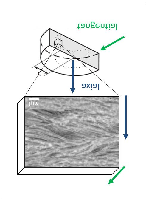
Strain Induced Anisotropic Magnetic Behaviour and Exchange Coupling Effect in Fe-SmCo5 Permanent Magnets
Generated by High Pressure Torsion A P REPRINT
As starting materials conventional powders (Fe: MaTeck 99.9% − 100 + 200 mesh; SmCo5 : Alfa Aesar, intermetallic
fine powder), which are stored and handled in an Ar filled glove box, are used to obtain the desired chemical composition.
The investigated compounds consist of 10, 24, 47 and 87 wt.% soft magnetic Fe and 90, 76, 53 and 13 wt.% hard
magnetic SmCo5 , respectively. Weighing the starting powders is very precise about an error below ±0.15 wt.%.
Additional EDX measurements along the cross-section on final samples, reveal an over-all-error of less than ±1.5 wt.%.
This does not hold for smaller specimen extracted at high applied strains exhibiting a separation into two phases: Here
the local chemical composition varies to a far greater extent and does not exactly average to an exact global sample
composition. The mixed powders are hydrostatically compacted under Ar-atmosphere using the HPT device at a
nominal pressure of 5 GPa and a quarter revolution. Shortly thereafter, the samples are severely deformed at 7.5 GPa
with a rotational frequency of 0.6 min−1 to avoid a significant increase of the processing temperature, which is further
suppressed by high pressure air cooling. These samples are denoted as room-temperature (RT) deformed samples in the
following. No prediction of the deformation behaviour of composites can be made on simple basis of the corresponding
material properties [13, 14]. During HPT-deformation at RT crack formation, a higher sample hardness and a limited
amount of revolutions is not avoidable for certain compositions. To apply a higher amount of strain while avoiding crack
formation, the influence of deformation temperature on the deformation behaviour and phase evolution, is investigated.
Hence, HPT-deformation at elevated temperatures (250 ◦ C and 400 ◦ C ) is carried out for selected samples.
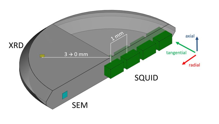
After deformation the samples are cut into pieces for specific investigations. A schematic drawing of an as-deformed
sample is depicted in Figure 1. The excised SQUID samples are displayed as well positions and directions, where
measurements are carried out. Scanning electron microscopy (SEM; LEO 1525, Carl Zeiss Microscopy GmbH,
Oberkochen, Germany) images are made in tangential direction as well as the backscattered electron detection mode
(BSE). Chemical evaluations are obtained with energy dispersive X-ray spectroscopy (EDX; XFlash 6–60, Bruker,
Berlin, Germany) while using the software package Esprit 2.2 from Bruker. For line-scans, an acceleration voltage of
3–5 keV is used, resulting in a calculated maximal excitation volume radius of 70 nm and the obtained data are averaged
over 7 pixels for smoothing. Vickers hardness measurements (Micromet 5104, Buehler, Lake Bluff, IL, USA) are
carried out in tangential direction on the polished sample along the diameter in steps of ∆r = 0.25 mm. A mean value is
calculated if the measured microhardness saturates in a plateau (usually valid for: 2.0 < r < 3.5 mm). Synchrotron X-ray
diffraction (XRD) measurements are carried out in axial orientation and transmission mode (Petra III: P07 synchrotron
facility at Deutsches Elektronen-Synchrotron DESY, Hamburg, Germany; Beam Energy: 100 keV; Beam Size: 0.2 ×
0.2 mm2 ). The signals are calibrated with a CeO2 reference and integrated with pyFAI. The processing software Fityk
is subsequently used for peak analysis. As theoretical reference peaks the Crystallography Open Database (COD) is
used (SmCo5 : COD 1524132, Fe: COD 9006587).
A SQUID-Magnetometer (Quantum Design MPMS-XL-7,Quantum Design, Inc., San Diego, CA, USA) operated
with the manufacturer’s software MPMSMultiVu Application (version 1.54) is used for magnetic measurements. The
hysteresis is measured at different temperatures in magnetic fields up to 70 kOe. Magnetic measurements are exclusively
performed at RT deformed samples. The magnetic field is applied in axial HPT-disc orientation, if not other stated. For
strain dependent measurements several SQUID samples are cut out of one HPT-disc (see Figure 1), whereas different
radii can be linked to a specific amount of strain according to Equation (1). Due to finite sample sizes, rather a range
of radii is observed instead of one specific radius. The investigated samples still represent bulk dimensional material,
meaning the applied strain is averaged within radii of ± 0.5 mm.
In Table 1, the processing parameters of all used samples in this study are summarised. Their chemical composition,
deformation temperature def.-temp, number of HPT-revolutions n and resulting strain γ at r = 3 mm, according to
Equation (1), is given.
3Strain Induced Anisotropic Magnetic Behaviour and Exchange Coupling Effect in Fe-SmCo5 Permanent Magnets
Generated by High Pressure Torsion A P REPRINT
Figure 1: Schematic illustration of a halved HPT-deformed disc. The positions of SQUID-samples at varying radii are
outlined (green boxes) with respect to the used cutting directions. Exemplarily axial XRD (yellow) and tangential SEM
(turquoise) measurements are indicated.
Table 1: Summarised processing parameters of used samples in this study. n depicts the number of torsions and γ(r3)
the shear strain at radius = 3 mm.
Nr Fe/wt.% SmCo5 /wt.% Def.-Temp n γ(r3)
1 10 90 RT 25 396
2 24 76 RT 25 445
3 47 53 RT 7 111
4 87 13 RT 14 206
5 47 53 250 ◦ C 8 118
6 47 53 400 ◦ C 18 265
3 Results
3.1 Influence of Processing Parameters on Structural Evolution
In Figure 2, the microstructure of the 47 wt.% Fe–53 wt.% SmCo5 sample HPT-deformed at 7 revolutions at RT is
shown for different positions along the HPT-disc. For all applied strains, a heterostructure is observed. In the center
of the HPT-disc, at radius about 0, the lowest amount of shear strain (γ ∼ 0 ) is applied and the material is mainly
deformed by compression. BSE images show an inhomogeneous structure with separated phases of Fe (dark contrast)
and SmCo5 (bright contrast). According to Equation (1), the applied strain increases with increasing radius: γ ∼ 37,
∼75 and ∼111 for r1, r2, r3, respectively. Plastic deformation is mainly observed in the Fe phase, limited plastic
deformation, a splitting and localized shearing of the SmCo5 phases is found. Nonetheless, a refinement of the structure
is noticed with increasing strain. This behaviour during HPT-deformation is also observed for all other investigated
chemical compositions (see Appendix A). The magnified image at r3 shows that the microstructural features become
very small and finely dispersed, but strong contrast changes in the BSE image reveal still separated Fe and SmCo5
phases. The phases are elongated in radial direction, but offer a thickness well below 1 µm in axial direction. At the
applied pressure it was not possible to fabricate samples with a higher strain due to slipping between sample and anvils.
The sample hardness saturates at 648 ± 15 HV.
By varying the Fe content in the initial powder mixtures, a larger amount of strain can be applied. Figure 3 shows the
microstructure at r3 of three different compositions at two different magnifications. The sample consisting of 10 wt.%
Fe–90 wt.% SmCo5 is depicted in Figure 3a) after 25 HPT revolutions. Strong contrast differences reveal the bright
SmCo5 matrix with small Fe rich areas at a strain of γ ∼ 396. The radial elongation of the Fe phase is in the range of a
few µm, while the axial dimension is significantly below 1 µm. Figure 3b) shows the microstructure of the sample
consisting of 24 wt.% Fe–76 wt.% SmCo5 , HPT-deformed for 25 revolutions corresponding to a strain of γ ∼ 445. At
lower magnifications the absence of contrast differences would indicate a homogeneous microstructure, which is not
confirmed when looking at higher magnifications. A lamellar morphology, well below 1 µm is still visible. A similarity
to the microstructure of the sample consisting of 47 wt.% Fe–53 wt.% SmCo5 (Figure 2) is noticed. A sample with
4Strain Induced Anisotropic Magnetic Behaviour and Exchange Coupling Effect in Fe-SmCo5 Permanent Magnets
Generated by High Pressure Torsion A P REPRINT
further increased Fe content (87 wt.% Fe–13 wt.% SmCo5 ) is shown in Figure 3c). 14 HPT rotations are applied which
corresponds to a strain of γ ∼ 206. The microstructure shows a Fe matrix with finely elongated SmCo5 phases. A
further deformation is limited by an immense hardness increase leading to crack formation at the used HPT conditions.
The microhardness of the samples in Figure 3a–c) reaches 616 ± 15, 657 ± 5 and 833 ± 11 HV, respectively.
Figure 2: BSE images at the same magnification of a HPT-deformed sample at RT consisting of 47 wt.% Fe–53 wt.%
SmCo5 at different radii. The higher magnified image is taken at r = 3 mm.
Figure 3: BSE images with two magnifications of HPT-deformed (RT) Fe-SmCo5 samples at r = 3 mm consisting of (a)
10, (b) 24 and (c) 87 wt.% Fe.
To investigate the lamellar microstructure in more detail, an EDX line-scan is carried out for one composition (47 wt.%
Fe–53 wt.% SmCo5 ). The scan direction is performed in axial HPT-disc direction, crossing the phases perpendicular
as can be seen in the image of the microstructure in Figure 4a) (top row). Strong changes of the Fe content can be
explained by sharp interfaces between the Fe and SmCo5 phase (Figure 4). Because the excitation volume of the
electron beam exceeds the dimension size of the phases, a smoothening occurs. Thus, the interaction volume of the
electron beam always interacts with both phases suppressing 100%-Fe peaks. The ratio between Co and Sm content is
calculated and analysed by a log-normal distribution which exhibits a peak at 4.84 ± 0.36. This closely corresponds to
the stoichiometric distribution of the starting material of SmCo5 and indicates that the phases remain unchanged during
deformation and refinement. Similar line-scans are performed on the sample deformed at 400 ◦ C . Here an increased
maximum of the distribution is found pointing towards a higher Co to Sm ratio (e.g., Sm2 Co17 ).
5Strain Induced Anisotropic Magnetic Behaviour and Exchange Coupling Effect in Fe-SmCo5 Permanent Magnets
Generated by High Pressure Torsion A P REPRINT
a) b)
100
Sm Fe
SmCo5
r0
r1
chemical composition [at. %]
r2
80 r3
log. Intensity [a.u.]
Co
60
40
20
Fe
0
0 1 2 3 4 5 6 7 8 20 25 30 35
-1
distance [µm] q [nm ]
Figure 4: (a) EDX line-Scan at r3 in axial direction for the 47 wt.% Fe–53 wt.% SmCo5 sample shown in Figure
2. The alternating Fe content represents the two-phase microstructure. (b) Synchrotron XRD measurements of the
RT-deformed 47 wt.% Fe–53 wt.% SmCo5 sample for different radii.
Another proof for the stability of the phases during the deformation process are synchrotron XRD measurements. In
Figure 4b) measurements of the 47 wt.% Fe–53 wt.% SmCo5 sample along the radius corresponding to the positions of
the BSE images in Figure 2 are presented. The theoretical reference peaks are in close accordance with the measured
ones. With increasing radius, a peak broadening due to a grain size decrease is visible. The formation of additional
phases cannot be observed.
Elevated deformation temperatures often helps to overcome processing limits, but usually lead to a final microstructure
with larger grain sizes of the as-deformed state in the respective phases [15]. Figure 5a) shows synchrotron XRD-pattern
for three Fe-SmCo5 samples consisting of 47 wt.% Fe–53 wt.% SmCo5 , which were HPT-deformed at RT, 250 ◦ C
and 400 ◦ C . With increasing temperature, the peaks are getting sharper indicating coarser grains, but the Fe and
SmCo5 phases remain stable up to a deformation temperature of 250 ◦ C . A strong difference is found at a deformation
temperature of 400 ◦ C . Several peaks are formed which cannot be related to the SmCo5 phase. The formation of
Sm2 Co7 and Sm2 Co17 phases is observed and examples of corresponding peaks are highlighted by black (Sm2 Co7 )
and blue (Sm2 Co17 ) arrows. To investigate the influence of the amount of strain for phase formations under elevated
deformation temperatures, the XRD-patterns of one 400 ◦ C-deformed sample are shown in Figure 5b) as a function of
radius. At r0 the peaks correspond to the theoretical references of Fe and SmCo5 . The formation of additional phases is
observed at higher radii, thus, the results show that the decomposition of SmCo5 into Sm2 Co7 and Sm2 Co17 is not
taking place at higher deformation temperature alone. The structural transition starts at a strain of γ ∼ 90 (r1 - blue
arrow in Figure 5 b) and is more pronounced at even higher amounts of strain.
6Strain Induced Anisotropic Magnetic Behaviour and Exchange Coupling Effect in Fe-SmCo5 Permanent Magnets
Generated by High Pressure Torsion A P REPRINT
a) b)
400°C Fe Fe r0
250°C SmCo5 SmCo5 r1
RT r2
r3
log. Intensity [a.u.]
log. Intensity [a.u.]
3.5
20 25 30 35 20 25 30 35
-1 -1
q [nm ] q [nm ]
Figure 5: Synchrotron XRD measurements of several Fe-47 wt.% samples deformed at different temperatures at r3
(a) and for the sample deformed at 400 ◦ C as a function of the radius (b). Examples of peak positions of the Sm2 Co7
(black) and Sm2 Co17 (blue) are indicated by arrows.
3.2 Magnetic Properties
The magnetic properties of RT-deformed Fe-SmCo5 compounds consisting of 87, 47, 24 and 10 wt.% Fe are measured
using a SQUID with the field applied in axial HPT-disc direction (see Figure 1). HPT-deformation induces a structure
with lamellar morphology, where a polycrystalline microstructure is still present in both phases. Therefore, the applied
magnetic field is perpendicular to this visible lamellar phase morphology. For every hysteresis measurement, a magnetic
field up to ±70 kOe is applied. In Figure 6, the measured magnetic moment is normalized to the mass of the sample
and plotted versus the applied magnetic field. Hysteresis measurements at 8 K reveal decoupled hysteresis loops:
The recoil curve (when the field is increased after demagnetisation) shows the behaviour of a superposition of a soft
and a hard magnetic phase, i.e., the behaviour of an exchange-spring magnet without coupling. This is because of
the formation of a ‘knee’ due to two separated independent phases [5]. Therefore, the soft magnetic α-Fe phase is
recognised by a high saturation magnetisation and a demagnetisation at low fields. The hard magnetic SmCo5 phase is
demagnetised at higher applied fields forming the ‘knee’. This effect can be seen in the hysteresis curve of all chemical
compositions, but is stronger pronounced at higher SmCo5 contents. At higher measurement temperatures, a coupling
between soft and hard magnetic phases is clearly present, showing less constriction of the (more smooth) hysteresis
curves. Hysteresis measurements at 300 K (red curves) cannot be explained by a simple superposition of a separate
Fe and SmCo5 hysteresis. Here an exchange coupling is turned on, displaying an overall concave hysteresis profile
with a concomitant decrease of coercivity. The mass saturation magnetisation is decreasing with decreasing Fe content.
In contrast, the value of the 8 K hysteresis lies slightly higher for all measurements. Although the maximal applied
magnetic field of the hysteresis is 70 kOe, a complete saturation for the samples consisting of 47, 24 and 10 wt.% Fe
cannot be ensured, see Figure 6b–d).
7Strain Induced Anisotropic Magnetic Behaviour and Exchange Coupling Effect in Fe-SmCo5 Permanent Magnets
Generated by High Pressure Torsion A P REPRINT
a) b)
200 200
8 K Fe-87 wt.% 8 K Fe-47 wt.%
300 K 300 K
]
]
-1
-1
magnetic moment [emu g
magnetic moment [emu g
100 100
10
50
]
-1
]
0 0
mag. mom. [emu g
-1
mag. mom. [emu g
5
25
0
0
-100 -100
-5
-25
-10
-50
-400 -200 0 200 400
-2000 0 2000
H / [Oe]
-200 -200 H / [Oe]
-40 -20 0 20 40 -40 -20 0 20 40
magnetic field [kOe] magnetic field [kOe]
c) d)
200 200
8 K Fe-24 wt.% 8 K Fe-10 wt.%
300 K 300 K
]
]
-1
-1
magnetic moment [emu g
magnetic moment [emu g
100 100
0 0
-100 -100
-200 -200
-40 -20 0 20 40 -40 -20 0 20 40
magnetic field [kOe] magnetic field [kOe]
Figure 6: Hysteresis loops of HPT processed Fe-SmCo samples measured at 300 K (red, dots) and 8 K (blue, cubes)
consisting of (a) 87, (b) 47, (c) 24 and (d) 10 wt.% Fe. All diagrams are identically scaled, therefore insets in (a,b) help
to directly compare the coercivities at different temperatures.
HPT-Induced Anisotropy
The influence of the HPT induced microstructure on the magnetic behaviour is investigated by applying a magnetic
field in different directions to the HPT disc for Fe-SmCo5 samples with a Fe content of 24 and 47 wt.% deformed at RT.
The field is applied either in axial direction of the HPT-disc (as described above) or in tangential sample direction. The
axial and tangential direction of the SQUID sample with respect to the HPT disc is visualized in Figure 1 as well as
in the inset of Figure 7. The respective directions are denoted as axial and tangential in the following. The axial and
tangential hysteresis of the selected samples consisting of 47 and 24 wt.% Fe are shown in Figure 7a) and b). A higher
susceptibility as well as a lower coercivity can be observed in the tangential direction, compared to the axial direction.
A considerable shift of the tangential hysteresis to negative magnetic fields for the Fe-47 wt.% sample and to positive
fields for the Fe-24 wt.% sample is visible. The difference between the positive and negative coercivities is ∼420 Oe
and ∼710 Oe for the Fe-24 wt.% and Fe-47 wt.% sample, respectively. While the axial hysteresis is measured first
and finished at a maximum applied field of 70 kOe, the fully magnetised samples are mounted in tangential direction
on the SQUID sample holder. Therefore, the direction of the shift is explained whether the sample is rotated up- or
downwards. Furthermore, the remanence is changed in both directions due to the shift. Looking at Figure 7b), specific
attention has to be given on the different saturation magnetisation values for the tangential hysteresis between positive
and negative fields. As mentioned before, a completely magnetised hysteresis for the low Fe-content samples in axial
direction cannot be assured. Due to the positive horizontal shift, the saturation magnetisation is not reached at positive
fields whereas for decreasing fields, the shift assists a full magnetisation process. Hence, the measured values for the
saturation magnetisation between applied negative and positive field of this hysteresis is different.
8Strain Induced Anisotropic Magnetic Behaviour and Exchange Coupling Effect in Fe-SmCo5 Permanent Magnets
Generated by High Pressure Torsion A P REPRINT
a) b)
150
150
100
]
]
-1 100
-1
magnetic moment [emu g
magnetic moment [emu g
Fe-47 wt.% Fe-24 wt.%
50
50 axial axial
tangential tangential
75 75
0 0
]
50 50
]
-1
-1
mag. mom. [emu g
mag. mom. [emu g
25 25
-50
0 -50 0
-25 -25
-100 -50 -50
-100
-75 -75
-4000 -2000 0 2000 4000 -10000 -5000 0 5000 10000
-150 magnetic field [Oe] magnetic field [Oe]
-150
-60 -40 -20 0 20 40 60 -60 -40 -20 0 20 40 60
magnetic field [kOe] magnetic field [kOe]
Figure 7: Hysteresis loops measured at 8 K in axial and tangential direction for Fe-SmCo5 samples with (a) 24 and (b)
47 wt.% Fe content. The inset shows the direction of the applied magnetic field compared to the HPT-disc.
3.3 Strain-Dependent Magnetic Properties
The influence of the applied strain on the magnetic properties is investigated for the Fe-SmCo5 sample containing 47
wt.% Fe–53 wt.% SmCo5 . The strain is calculated according to Equation 1 for integer radii and the measured hysteresis
correspond to different applied strains (Figure 8). All samples have dimensions of several hundred µm in all spatial
directions as shown in Figure 1. As a result, the sample preserves not a specific amount of applied strain, it rather
varies as a linear relation of their radial position. In the following the radius is used as sample indication and the reader
is referred to Figure 2, where the microstructure of the samples is shown. At r0, the spacing of the phases is larger
than 50 µm as can be seen in Figure 8, which changes drastically when looking at r1. Here, the deformation process
leads to a two-phase microstructure where the SmCo5 phase is fragmented and elongated, the spacing of the phases
is significantly below 50 µm in the axial direction. At r2 and r3, the morphology is further refined, where the axial
dimension for the SmCo5 phase is below 10 µm at r2 and well below 1 µm at r3. An exchange coupled hysteresis is
found at 300 K for all samples. Therefore, it must be noticed again, that a relatively low applied strain for the sample at
r0 corresponds to a radius between 0 < r ≤ 0.5 mm (0 < γ < 20) and already results in an exchange coupled magnet. At
r2 (γ = 75) a maximum of the coercivity is found (∼2000 Oe at 300 K and ∼3500 Oe at 8 K). Decoupled hysteresis are
found at 8K, whereas the ’knee’ is most pronounced for strains of γ = 37 to 75. At a maximum strain of γ = 111, the
appearance of the ’knee’ as well as the coercivity decreases again.
9Strain Induced Anisotropic Magnetic Behaviour and Exchange Coupling Effect in Fe-SmCo5 Permanent Magnets
Generated by High Pressure Torsion A P REPRINT
a) b)
8 K 8 K
150 150
300 K 300 K
]
]
-1
-1
magnetic moment [emu g
magnetic moment [emu g
100 radius 0 100 radius 1
50 50
]
]
-1
-1
mag. mom. [emu g
mag. mom. [emu g
25 25
50 50
0 0
-25 -25
0 0
-50 -50
-4000 -2000 0 2000 4000 -4000 -2000 0 2000 4000
H / [Oe] H / [Oe]
-50 -50
0 20 40 60 0 20 40 60
magnetic field [kOe] magnetic field [kOe]
c) d)
8 K 8 K
150 150
300 K 300 K
]
]
-1
-1
magnetic moment [emu g
magnetic moment [emu g
100 radius 2 100 radius 3
50 50
]
]
-1
-1
mag. mom. [emu g
mag. mom. [emu g
25 25
50 50
0 0
-25 -25
0 0
-50 -50
-4000 -2000 0 2000 4000 -4000 -2000 0 2000 4000
H / [Oe] H / [Oe]
-50 -50
0 20 40 60 0 20 40 60
magnetic field [kOe] magnetic field [kOe]
Figure 8: Hysteresis loops of HPT processed Fe-SmCo samples measured at 300 K (red, dots) and 8 K (blue, cubes) of
a 47 wt.% Fe–53 wt.% SmCo5 sample at a) r0, b) r1, c) r2 and d) r3.
4 Discussion
In this work, Fe-SmCo5 composites with different amounts of Fe are processed by HPT-deformation. SmCo5 exhibits a
hexagonal crystal structure, whereas α-Fe is body centered cubic. During HPT-deformation, no ideal co-deformation of
both phases takes place, Fe covers more strain than SmCo5 particles. Nevertheless, both phases are refined resulting in
an alternating finely dispersed phase morphology with a phase spacing in the 100 nm regime. Compared to a cubic
crystal, hexagonal structures provide less sliding planes and are more prone to localized shear and brittle behaviour. The
deformation of hexagonal crystal structures is usually limited by pronounced crack formation or accompanied by phase
transformations [13, 16, 11, 17, 18]. Especially at low strains, the SmCo5 phase shows a lack of phase deformation and
the formation of cracks in this phase is visible. Nonetheless, fragmentation and phase refinement is observed. However,
most of the plastic deformation is localized in the Fe phase, where grain refinement as in single phase HPT deformed
Fe is expected. When the composites are exposed to a higher amount of strain, the SmCo5 phase is plastically deformed
to a higher extend. For the Fe phase, a grain refinement with increasing strain is observed instead. It is assumed,
that fracturing and localized shear of the brittle and mechanically harder SmCo5 phase dominates the deformation
behaviour until the hardness of the Fe and SmCo5 phase converges due to the grain refinement of the Fe phase. Then,
the SmCo5 phase provides a higher plasticity [19]. However, local mutual hardness differences might lead to a partial
co-deformation or an alternating deformation of the two phases. The rheologically harder phase tends to local necking
and breaks into smaller fragments leading to the even more refined structure at the highest strains [20]. However, the
possibility to deform hexagonal SmCo5 is noticeable.
For exchange coupled magnets two magnetic phases are necessary. Thereby the hard magnetic material is the main
phase, providing a high anisotropy and coercivity. The addition of a soft magnetic phase reduces the anisotropy and
coercivity, but enhances the magnetisation and remanence [21]. Depending on morphology (e.g., spheres, layers,
cylinders) of the dispersion and used hard and soft magnetic materials, a maximised theoretical energy product can be
10Strain Induced Anisotropic Magnetic Behaviour and Exchange Coupling Effect in Fe-SmCo5 Permanent Magnets
Generated by High Pressure Torsion A P REPRINT
achieved. The energy product usually peaks around 30 wt.% soft magnetic material, which emphasizes the importance
of a hard magnetic material matrix, which encloses the soft magnetic phase. Another crucial parameter is the exchange
length for the soft magnetic material. Because of the small magnetic anisotropy constant of the soft phase, the spin
orientation of the hard phase induces an exchange coupling into the soft phase. At the interface the spins of the soft
phase align with the hard phase. This usually holds if the dimensions of the soft phase do not exceed a range of twice
the exchange length
s
sof t Asof t
lex = (2)
K1sof t
where A denotes the exchange constant and K the anisotropy constant (for α-Fe: A = 2.5 × 10⁻¹¹ Jm−1 , K1 = 4.6 ×
104 Jm−3 , lex = 23 nm) [22, 5]. SEM investigations (Figures 2, 3 and 4a) show a fine phase morphology in the 100 nm
regime, sustained by a peak broadening in XRD experiments (Figure 4b). The dimensions of the phases being small
enough, are confirmed by the measured magnetic properties. As depicted in Figure 6, completely exchange coupled
hysteresis with a concave shape are found. The results are comparable to magnetic measurements received of ball
milled Fe-SmCo powders [2].
By analysing the virgin curves presented in Figure 6, a material classification between nucleation controlled and pinning
controlled magnets can be given [23]. While existing domains are easily expanded in nucleation controlled magnets,
microstructural obstacles (e.g., dislocations or vacancies, such as they occur after HPT deformation) impede the
movement of domain walls, which act as pinning centers. Therefore, the initial susceptibility is lower and the saturation
magnetisation is reached at higher fields indicating a pinning controlled magnetic material after HPT-deformation.
The hysteresis shapes at 8 K strongly differ from the 300 K curves, where exchange coupling is found. Hysteresis curves
showing such a ’knee’ at low temperatures are suggested as a decoupled compound, when hard and soft magnetic phases
do not interact and are measured as magnetically independent phases [5]. The effect, that decoupling at decreasing
temperatures occurs, can be explained by a temperature dependence of the magnetocrystalline anisotropy of the hard
SmCo5 phase [24]. As the anisotropy increases with decreasing temperature, according to Equation (2) the exchange
length decreases [25]. Therefore, the ratio between total volume and exchange coupled volume diminishes at lower
temperatures [26].
The shapes of tangential and axial hysteresis in Figure 7b) are completely different. In axial direction a sheared
and decoupled hysteresis is visible. The tangential curve offers a higher susceptibility with nearly no decoupling
characteristics. This behaviour is similar for the hysteresis in Figure 7a) besides a stronger pronounced decoupling
due to the higher SmCo5 content. Both tangential hysteresis are horizontally shifted which can be explained by the
microstructure and the magnetic nucleation field. In the literature, a texture formation of hexagonal crystal structures
is often observed during HPT-deformation. Therefore, the c-axis orientates into the shearing or tangential direction
[17, 27, 28]. Furthermore, the c-axis also represents the magnetically easy axis, which means that all SmCo5 crystals
are easily demagnetised. In the case of the used SmCo5 material, this also explains the higher susceptibility compared
to the axial hysteresis. Hence, we assume that the microstructure of HPT-deformed Fe-SmCo5 composites consists of a
lamellar-like structure with the easy axis of the hard magnetic phase oriented in tangential direction. The soft magnetic
spins align in the same direction. When the field is reversed areas with opposite spins have to be formed. This requires
a so called nucleation field Hn and is described by
K hard
Hn ∼
= (3)
µ0 Mssof t
where K is the anisotropy constant and Ms the saturation magnetisation [5, 29]. If the hysteresis cannot be demagnetised
completely, a pinning between hard and soft magnetic spins remains. The nucleation field is changed due to a varying
magnetisation and the material is demagnetised at different fields.
In the literature, ball milling experiments, as a processing technique using plastic deformation, are mainly used to
fabricate Fe-SmCo5 magnets. Although the production technique differs a lot, comparisons of the results can be made.
Rong et al. [2] reported a decrease in coercivity when milling the powder up to 10 h. They describe the formation of an
amorphous structure, due to a reduced hard-phase stability. Further, they found an increasing saturation magnetisation
because of the formation of a FeCo-alloy providing a higher magnetisation compared to α-Fe. During HPT also a strong
decrease in coercivity and a slight increase in the magnetisation is found when the applied strain of the HPT-deformed
sample exceeds γ = 75. Besides a slight peak broadening, no amorphization is found in our corresponding synchrotron
XRD measurements (Figure 4b), which could explain the coercivity deterioration. Detailed TEM studies at the interfaces
between the Fe-SmCo5 interfaces could reveal the formation of a small non-magnetic layer in between, if a slight
11Strain Induced Anisotropic Magnetic Behaviour and Exchange Coupling Effect in Fe-SmCo5 Permanent Magnets
Generated by High Pressure Torsion A P REPRINT
decomposition of the SmCo5 structure is present. However, this is beyond the scope of this work, which aims to show
that HPT-deformation is an alternative process to manufacture exchange coupled nanocomposites.
Therefore, future investigations will cover the influence of applied amount of strain on the magnetic behaviour for
different chemical compositions and other phases. For example, the magnetic properties will be enhanced when Fe is
substituted by FeCo alloys and SmCo5 by other SmCo based intermetallic phases such as Sm2 Co7 or Sm2 Co17 . The
HPT-parameters, such as a different deformation temperature, will be adjusted and could lead to a better deformation
performance, while the phases remain stable. In the present study it could be shown that Fe and SmCo5 phases remain
stable until 250 ◦ C (see Figure 5a). Moreover, the stability of the finely dispersed heterostructure of the magnets will
be tested by annealing at higher temperatures to show the utilization for technical applications. Finally, subsequent
annealing treatments at low temperatures after deformation are expected to reduce crystal defects, introduced by the
shearing process, which again is expected to improve magnetic performance.
5 Conclusions
For the first time, the possibility of producing nanostructured Fe-SmCo exchange spring magnets by HPT-deformation
over a broad chemical composition range is demonstrated. HPT-deformation at elevated temperatures (T > 250 ◦ C )
leads to a strain induced phase transformation of the SmCo-phase, whereas room temperature deformation allows the
production of a defined heterogeneous nanostructured morphology preserving the soft-magnetic Fe phase and hard
magnetic SmCo5 -phase. In contrast to other techniques, it is possible to fabricate nanostructured bulk samples already
exhibiting dimensions of several centimetres without any thermal compaction or sintering process. Spring magnetic
behaviour at 300 K and a decoupling effect at lower temperatures (8 K) are found for all chemical compositions.
HPT-deformation leads to an anisotropic microstructure, which is magnetically investigated for two different chemical
compositions in axial and tangential HPT-disc directions. The influence of the applied strain on the magnetic properties
is investigated on the Fe-SmCo5 sample with medium composition, revealing an optimum amount of strain of γ = 75,
for the used initial powder size, showing the highest coercivity.
Author Contributions: Conceptualization, L.W. and A.B.; Methodology, L.W., S.W. and A.B.; Validation, L.W., M.S.,
S.W., P.K., H.K., R.P. and A.B.; Formal Analysis, L.W.; Investigation, L.W.; Data Curation, L.W.; Writing—Original
Draft Preparation, L.W.; Writing—Review and Editing, R.P., H.K., P.K., M.S., S.W., and A.B.; Visualization, L.W.;
Supervision, H.K., P.K., R.P. and A.B.; Project Administration, A.B.; Funding Acquisition, A.B. All authors have read
and agreed to the published version of the manuscript.
Funding: This project has received funding from the European Research Council (ERC) under the EuropeanUnion’s
Horizon 2020 research and innovation programme (Grant No. 757333).
Acknowledgments: The measurements leading to these results have been performed at PETRA III: P07 at DESYHam-
burg (Germany), a member of the Helmholtz Association (HGF). We gratefully acknowledge the assistance by Norbert
Schell and further thank F. Spieckermann and C. Gammer for their help with data processing. L.W. deeply appreciates
the help of Mirjam Spuller and Georg Holub for specimen preparation.
Conflicts of Interest: The authors declare no conflict of interest.
Abbreviations
The following abbreviations are used in this manuscript:
BSE Backscattered Electrons
COD Crystallography Open Database
EDX Energy Dispersive X-ray Spectroscopy
HPT High-Pressure Torsion
RT Room Temperature
SEM Scanning Electron Microscopy
SPD Severe Plastic Deformation
SQUID Superconducting Quantum Interference Device
TEM Transmission Electron Microscopy
A Radial Microstructure
In this section, supplementary information on the processed samples is given. The change of the microstructure as a
function of applied strain is described in detail for sample Nr. 3 in Section 3.1. Similarities are found for sample Nr. 1,
12Strain Induced Anisotropic Magnetic Behaviour and Exchange Coupling Effect in Fe-SmCo5 Permanent Magnets
Generated by High Pressure Torsion A P REPRINT
2 and 4, depicted in Figures 9, 10 and 11, respectively. The radial microstructure for samples deformed at elevated
temperatures is found in Figures 12 (250 ◦ C ) and 13 (400 ◦ C ).
Figure 9: BSE images of a HPT-deformed sample (Nr. 1) at RT consisting of 10 wt.% Fe–90 wt.% SmCo5 at different
radii. The scale bar in r0 also applies to r1 and r2. Images of two magnifications are presented for r3.
Figure 10: BSE images of a HPT-deformed sample (Nr. 2) at RT consisting of 24 wt.% Fe–76 wt.% SmCo5 at different
radii. The scale bar in r0 also applies to r1 and r2. Images of two magnifications are presented for r3.
13Strain Induced Anisotropic Magnetic Behaviour and Exchange Coupling Effect in Fe-SmCo5 Permanent Magnets
Generated by High Pressure Torsion A P REPRINT
Figure 11: BSE images of a HPT-deformed sample (Nr. 4) at RT consisting of 87 wt.% Fe–13 wt.% SmCo5 at different
radii. The scale bar in r0 also applies to r1 and r2. Images of two magnifications are presented for r3.
Figure 12: BSE images of a HPT-deformed sample (Nr. 5) at 250 ◦ C consisting of 47 wt.% Fe–53 wt.% SmCo5 at
different radii. The scale bar in r0 also applies to r1 and r2. Images of two magnifications are presented for r3.
14Strain Induced Anisotropic Magnetic Behaviour and Exchange Coupling Effect in Fe-SmCo5 Permanent Magnets
Generated by High Pressure Torsion A P REPRINT
Figure 13: BSE images of a HPT-deformed sample (Nr. 6) at 400 ◦ C consisting of 47 wt.% Fe–53 wt.% SmCo5 at
different radii. The scale bar in r0 also applies to r1 and r2. Images of two magnifications are presented for r3.
References
[1] A Ray and K Strnat. Magnetic properties of rare earth-cobalt phases r5 co19 . IEEE Transactions on Magnetics,
11(5):1429–1430, 1975.
[2] Chuanbing Rong, Ying Zhang, Narayan Poudyal, Izabela Szlufarska, Rainer J Hebert, MJ Kramer, and J Ping
Liu. Self-nanoscaling of the soft magnetic phase in bulk smco/fe nanocomposite magnets. Journal of materials
science, 46(18):6065–6074, 2011.
[3] Oliver Gutfleisch. Controlling the properties of high energy density permanent magnetic materials by different
processing routes. Journal of Physics D: Applied Physics, 33(17):R157, 2000.
[4] Oliver Gutfleisch, Matthew A Willard, Ekkes Brück, Christina H Chen, SG Sankar, and J Ping Liu. Magnetic
materials and devices for the 21st century: stronger, lighter, and more energy efficient. Advanced materials,
23(7):821–842, 2011.
[5] Eckart F Kneller and Reinhard Hawig. The exchange-spring magnet: a new material principle for permanent
magnets. IEEE Transactions on Magnetics, 27(4):3588–3560, 1991.
[6] Ralph Skomski and JMD Coey. Giant energy product in nanostructured two-phase magnets. Physical Review B,
48(21):15812, 1993.
[7] PK Sahota, Yi Liu, Ralph Skomski, Priyanka Manchanda, R Zhang, Matteo Franchin, Hans Fangohr, George C
Hadjipanayis, Arti Kashyap, and David J Sellmyer. Ultrahard magnetic nanostructures. Journal of Applied
Physics, 111(7):07E345, 2012.
[8] Eric E Fullerton, JS Jiang, and SD Bader. Hard/soft magnetic heterostructures: model exchange-spring magnets.
Journal of Magnetism and Magnetic Materials, 200(1-3):392–404, 1999.
[9] Ruslan Zafarovich Valiev, Rinat K Islamgaliev, and Igor V Alexandrov. Bulk nanostructured materials from severe
plastic deformation. Progress in materials science, 45(2):103–189, 2000.
[10] Anton Hohenwarter, Andrea Bachmaier, Bernd Gludovatz, Stephan Scheriau, and Reinhard Pippan. Technical
parameters affecting grain refinement by high pressure torsion. International Journal of Materials Research,
100(12):1653–1661, 2009.
[11] Kaveh Edalati and Zenji Horita. A review on high-pressure torsion (hpt) from 1935 to 1988. Materials Science
and Engineering: A, 652:325–352, 2016.
15Strain Induced Anisotropic Magnetic Behaviour and Exchange Coupling Effect in Fe-SmCo5 Permanent Magnets
Generated by High Pressure Torsion A P REPRINT
[12] A Hohenwarter and R Pippan. Sample size and strain-rate-sensitivity effects on the homogeneity of high-pressure
torsion deformed disks. Metallurgical and Materials Transactions A, 50(2):601–608, 2019.
[13] Karoline Sophie Kormout, Reinhard Pippan, and Andrea Bachmaier. Deformation-induced supersaturation in
immiscible material systems during high-pressure torsion. Advanced Engineering Materials, 19(4):1600675,
2017.
[14] Reinhard Pippan, Stephan Scheriau, Aidan Taylor, M Hafok, A Hohenwarter, and A Bachmaier. Saturation of
fragmentation during severe plastic deformation. Annual Review of Materials Research, 40:319–343, 2010.
[15] O Renk and R Pippan. Saturation of grain refinement during severe plastic deformation of single phase materials:
reconsiderations, current status and open questions. Materials transactions, 60(7):1270–1282, 2019.
[16] A Bachmaier, H Krenn, P Knoll, H Aboulfadl, and R Pippan. Tailoring the magnetic properties of nanocrystalline
cu-co alloys prepared by high-pressure torsion and isothermal annealing. Journal of Alloys and Compounds,
725:744–749, 2017.
[17] H Wang, Wojciech Dmowski, Z Wang, J Qiang, K Tsuchiya, Y Yokoyama, Honbin Bei, and Takeshi Egami.
Transformation pathway from alpha to omega and texture evolution in zr via high-pressure torsion. Applied
Physics Letters, 114(6):061903, 2019.
[18] Martin Stückler, Heinz Krenn, Reinhard Pippan, Lukas Weissitsch, Stefan Wurster, and Andrea Bachmaier.
Magnetic binary supersaturated solid solutions processed by severe plastic deformation. Nanomaterials, 9(1):6,
2019.
[19] SS Kiparisov, IA Kiyanskii, and VE Perel’man. Theoretical and experimental investigation of the process of
plastic deformation of sintered composite materials iv. technological basis for controlling the state of the elements
of the “hard” phase during deformation. Soviet Powder Metallurgy and Metal Ceramics, 26(11):899–902, 1987.
[20] I-W Chen, EJ Winn, and M Menon. Application of deformation instability to microstructural control in multilayer
ceramic composites. Materials Science and Engineering: A, 317(1-2):226–235, 2001.
[21] Ralph Skomski, Priyanka Manchanda, Pankaj Kumar, Balamurugan Balamurugan, Arti Kashyap, and David J
Sellmyer. Predicting the future of permanent-magnet materials. IEEE Transactions on Magnetics, 49(7):3215–
3220, 2013.
[22] H Kronmüller, R Fischer, M Seeger, and A Zern. Micromagnetism and microstructure of hard magnetic materials.
Journal of Physics D: Applied Physics, 29(9):2274, 1996.
[23] Karl J Strnat and Reinhold MW Strnat. Rare earth-cobalt permanent magnets. Journal of Magnetism and Magnetic
Materials, 100(1-3):38–56, 1991.
[24] SG Sankar, VUS Rao, E Segal, WE Wallace, WGD Frederick, and HJ Garrett. Magnetocrystalline anisotropy of
sm co 5 and its interpretation on a crystal-field model. Physical Review B, 11(1):435, 1975.
[25] J Ping Liu, Ralph Skomski, Yi Liu, and David J Sellmyer. Temperature dependence of magnetic hysteresis of rco
x: Co nanocomposites (r= pr and sm). Journal of Applied Physics, 87(9):6740–6742, 2000.
[26] LP Muñoz Ortega, JT Elizalde Galindo, JR Farias Mancilla, CR Santillan, and JA Matutes Aquino. Temperature
effect on dipolar and exchange interactions for smco5+ fe65co35 nanocomposite powders. Journal of Applied
Physics, 111(7):07B505, 2012.
[27] BJ Bonarski, E Schafler, B Mingler, W Skrotzki, B Mikulowski, and MJ Zehetbauer. Texture evolution of mg
during high-pressure torsion. Journal of materials science, 43(23-24):7513–7518, 2008.
[28] Yi Huang, Roberto B Figueiredo, Thierry Baudin, Anne-Laure Helbert, François Brisset, and Terence G Langdon.
Microstructure and texture evolution in a magnesium alloy during processing by high-pressure torsion. Materials
Research, 16(3):577–585, 2013.
[29] ZJ Guo, JS Jiang, JE Pearson, SD Bader, and JP Liu. Exchange-coupled sm–co/nd–co nanomagnets: correlation
between soft phase anisotropy and exchange field. Applied physics letters, 81(11):2029–2031, 2002.
16You can also read