SUPPORT SYSTEMS for HIGH-DENSITY ORCHARDS ( 2018) - BC Fruit Growers' Association
←
→
Page content transcription
If your browser does not render page correctly, please read the page content below
SUPPORT SYSTEMS for HIGH-DENSITY ORCHARDS (2018)
This manual is a revision to:
Support Systems for High Density Orchards by K. Bert Van Dalfsen, 1989.

        Funding for this revision of the manual was provided by:

                             Prepared by:
                         Keith Duhaime P.Ag.
         (Tel. 250.215.2640 E-mail: keith.duhaime@gmail.com)
                                  and
                      Dwayne D. Tannant, P.Eng.

       Cover photo: Okanagan orchard with trellis support system

                                   ii
CONTENTS

1 Introduction ....................................................................................................................... 1
    1.1   Benefits ........................................................................................................................................... 1
    1.2   Trellises can Fail .............................................................................................................................. 1
    1.3   Costs of Failure ............................................................................................................................... 2
    1.4   Preventing Trellis Failure ................................................................................................................ 2
2 Trellis Design ...................................................................................................................... 3
    2.1   Posts................................................................................................................................................ 3
    2.2   Line Posts ........................................................................................................................................ 3
    2.3   Single End Post ................................................................................................................................ 4
    2.4   H-Frame Posts ................................................................................................................................. 5
    2.5   Single Post with a Tie-Back Anchor ................................................................................................. 7
    2.6   Addition of an End-post to a Post with a Tie-Back .......................................................................... 8
    2.7   Wire Spacing and Tension ............................................................................................................. 10
3 Soil Considerations ........................................................................................................... 10
4 Trellis Components .......................................................................................................... 12
    4.1   Posts.............................................................................................................................................. 12
    4.2   Wire .............................................................................................................................................. 14
    4.3   Staples........................................................................................................................................... 15
    4.4   Wire Connection, Termination, and Tensioning ........................................................................... 16
    4.5   Soil Anchors .................................................................................................................................. 17
5 Trellis Maintenance .......................................................................................................... 18
Acknowledgements .............................................................................................................. 19
Funding ................................................................................................................................ 19
Disclaimer ............................................................................................................................ 19
References............................................................................................................................ 20

                                                                             iii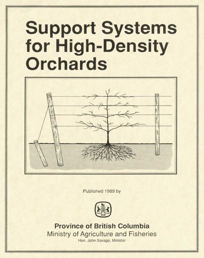
Support Systems for High-Density Orchards (2018)

1 Introduction
High-density dwarf tree fruit production is a common practice in BC orchards. The spindle-type
tree is grafted or budded to a dwarf rootstock. These spindle-type trees produce fruit faster and at
higher densities than traditional trees. The ability to quickly implement newer varieties that
better meet market demands and improve financial returns make high density production
attractive. However, the system has challenges. The limited branch framework of dwarf trees
provides insufficient support for the crop, and hence a support system, also known as a trellis, is
necessary for supplemental support.

1.1 Benefits
High-density orchards using trellises for support are initially more expensive to implement than
traditional plantings but are more efficient and profitable over their production life. A trellis
provides the following advantages:
• Encourages trees to put energy into fruit production instead of producing wood.
• Provides a uniform structure for tree training, promoting uniform growth.
• Improves light interception and uniformity of fruit quality and ripening.
• Produces earlier yields, potentially within two years of planting, and higher total yields over
   the life of the orchard.
• Reduces labour costs and encourages more uniform pruning, training, and thinning.
• Reduces damage to fruit and grafts by reinforcing trees against the wind.
• Facilitates the management of orchards as fruiting walls in two dimensions.
They also facilitate emerging technologies such as increased automation and mechanization to
enhance productivity, quality, and efficiency. Trellises can also be used to cover the orchard with
netting to protect the fruit.

1.2 Trellises can Fail
Trellises can fail. Figure 1 illustrates why. To be successful, a trellis must stand for the full life
of the planting, typically 20 years. During this time, the capacity of the trellis system must
always be greater than the load they are required to carry.

                                              trellis capacity

                                        safety margin

                                                   load on trellis system

                                                 orchard life
                               0                   10                       20
                                               Time (years)

            Figure 1 Evolution of trellis loads and trellis capacity over the life of the orchard.

                                                      1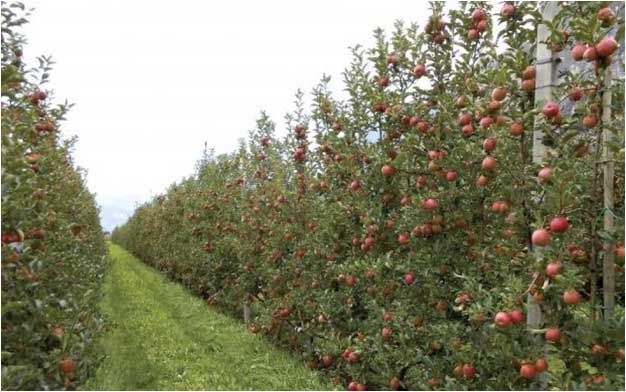
It is important to recognize that the loads on and the capacity of a trellis change over the life of
the planting.
• In the first two to three years, loads are relatively light as the planting establishes itself. At the
   same time, the trellis system is at its maximum strength.
• As trees grow and produce more fruit, typically from years five to eight, they exert a greater
   weight on the trellis and wind loads increase with greater foliage. Meanwhile, the trellis may
   begin to weaken due to:
    o Post rot where wooden posts enter the ground.
    o Corrosion of wire and hardware.
    o Cyclic wind loads, weakening posts, wire, connectors, and soil.
    o Operational wear and tear.
• After eight to ten years, loads may stabilize and slightly decrease on the trellis as spindles
   thicken and carry a bit more load, but the trellis system will potentially lose significant load
   capacity as a result of advancing post rot, and corrosion and fatigue of wire and metal.
If the loads on the trellis exceed the capacity of the trellis, it will fail.

1.3 Costs of Failure
Trellis failures can be costly. These costs can include:
• Reduced crop production directly from failure site itself and indirectly in opportunity costs.
• Lower crop quality from damage (e.g., bruising).
• Time, materials, and labour required to repair or mitigate damage.
Failure also means the loss of potential to implement new technologies and methods in the future
to improve production and profits.

1.4 Preventing Trellis Failure
A properly functioning trellis is the product of good planning and implementation. Each support
system must be uniquely designed for its site and application. It should not be assumed that the
design of a support system on a neighboring orchard is adequate for the current application.
At the time of planting, the materials and construction that comprise a support system are near
their peak performance, but experience minimal loads.
To overcome the challenges posed to support systems during their operational life and to
mitigate failure, orchardists must use:
• A support system designed to provide adequate strength and resilience for its service life.
• Recommended materials that meet the design requirements of the system.
• Proper construction techniques in implementing support systems.
• Best practices in the use and maintenance of the support system over its service life.
This manual will guide producers in design and construction of trellises, the materials and
methods used in their construction, and the expected costs.

Trellises must be designed and built for the full life of the orchard (20 years) to assure success.
What may appear to be an overdesigned support system at the time of installation may only have
a small safety margin for its capacity near the end of the orchard lifespan

                                                     2
Support Systems for High-Density Orchards (2018)

2 Trellis Design
2.1 Posts
A trellis support system relies on posts and wires to support the weight of the trees and fruit,
including wind loads. Larger posts installed at a greater depth create a stronger system. Not only
is the post itself stronger but the lateral resistance to post overturning is higher because the forces
acting on posts are distributed over a larger contact area. Increasing the post embedment in the
soil will significantly increase the load capacity of the support system. The support system
capacity is also dependant on the strength of the soil around the post.
The soil around driven posts will provide more resistance to wire and wind loads compared to a
post installed in an auger borehole. Therefore, drive the posts where possible because a driven
post can be 50% stronger than an augered posts. Driving posts is done most effectively by using
a hydraulic post driver.
The support posts are typically installed in a straight line. The posts at each end of the line (end-
posts) will carry more load than the posts within the line of posts (line-posts). The end-posts are
designed differently than the line-posts. The designs presented here consider a recommended
standard for line-posts and different design options for the end-posts.
The recommended post diameters presented in this manual refer to the minimum diameter of
the post. For example, a 4” post can range up to 5” in diameter. The larger posts should always
be selected and used for the end-posts.

2.2 Line Posts
The recommended design for a line-post is shown in Figure 2.

The recommended post is 12’ long and 4” in diameter. The recommended spacing between line
posts is 30’ (10 m).
The post spacing should be reduced wherever the trellis goes over rises or dips in the land, or if
the line of posts along a trellis has a slight bend.
Each post should be driven 3’ into the ground. The 12’ long posts can hold the top wire nearly 9’
above the ground. The recommended post size, depth of placement, and spacing are based on:
• Post strength. A 4” diameter post may seem excessive in the first years of establishing a new
  orchard. However, there is real potential for post rot, even with pressure-treated wood to the
  CSA O80 standard. Posts used in orchards and vineyards are often subject to regular
  applications of irrigation water, and despite no visible evidence of rot, a loss of 50% of a
  post’s strength is possible in the ‘rot zone’ over the 20-year life of the orchard. Furthermore,
  the ‘rot zone’ portion of the post is also subjected to the greatest forces.
• Soil strength. The soil strength varies with soil texture and density. The 30’ recommended
  spacing is based on calculations using the Trellx tool for sandy-gravel soils, which are
  common in the tree fruit growing regions of BC. However, there are soils with higher clay
  content in BC, and these can be weaker, especially under wet conditions. In these situations,
  post spacing should be reduced, or longer posts (14’) should be used and driven deeper.

                                                  3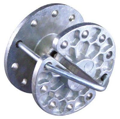
30’ post spacing
                                                       on flat ground

                                                      ~2’

                               12’ posts                      support wires
                             4” diameter               2’       12.5 Ga. HT
                           25 year warranty                 class 3 galvanized

                                                       2’

                                                       3’

                                                       3’

                 Figure 2 Recommended line-post wire spacing and embedment depth.

• Wind speed. The 30’ spacing is based on the trellis experiencing a wind speed of 50 km/h
  (30 mph) with a full fruit wall typical of the late summer and early fall (August to October).
  However, historical data have shown that gusts of wind up to and greater than 75 km/h
  (45 mph) can occur during this same period. Calculations using the Trellx tool indicate that
  with winds of 80 km/h, the same 12’ by 4” posts at the 3’ depth should be spaced less than half
  the distance apart (15’).
Finally, if the posts are also used to hold netting over the trees, then longer (16’) posts should be
used to provide sufficient height.

2.3 Single End Post
The simplest end-post design is a single post that has a larger diameter and deeper depth of
embedment than the line-posts. If the trellis is used in soil conditions that have relatively high
strength, then a single end-post as illustrated in Figure 3 should be sufficient.
The single end-post is the simplest but also the weakest design. The loads in the trellis wires
terminate at the end-post and thus pull the end-post towards the line-posts. The soil around the
post resists this load. The post itself also has a bending resistance to the wire loads.

                                                  4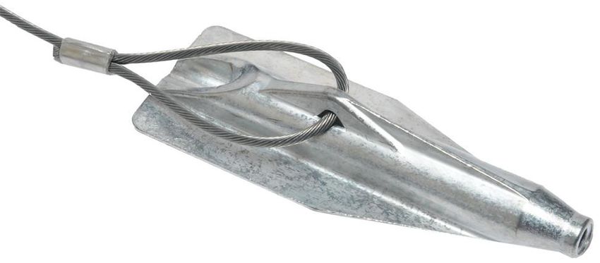
Support Systems for High-Density Orchards (2018)

                                                  2’

                                                                   support wires
                                                  2’                12.5 Ga. HT
                                                                 class 3 galvanized

                         10%                      2’
                         or 6°

                                                  3’

                              1’

                     14’ post
                   6” diameter                    4’
                 25 year warranty

               Figure 3 End-post consisting of a 6” post embedded deep into the ground.

The recommended post is 14’ long and 6” in diameter. Each post should be embedded 4’ into the
ground. The post should be pounded into the ground at a slight angle 10:1 (ratio between vertical
distance and horizontal distance) as shown in Figure 3. This also translates into a 10% or 6o lean
off of vertical. The larger post diameter and deeper embedment are essential to handle the
bending loads that will be placed on the post by the wires.
A single end-post will likely move towards a vertical orientation over time as the loads increase
in the orchard and fluctuate on the wires. The trellis wires should be re-tensioned if the post
moves in the ground.

2.4 H-Frame Posts
The H-frame system uses two end-posts to effectively share the wire loads and transfer them to
the soil. The recommended posts are 6” in diameter and at least 12’ long. Each post should be
driven a minimum of 3’ into the ground. When the soil is weak, use 14’ posts and embed them 4’
deep to keep the top wire 9’ above the ground as shown in Figure 4.

                                                  5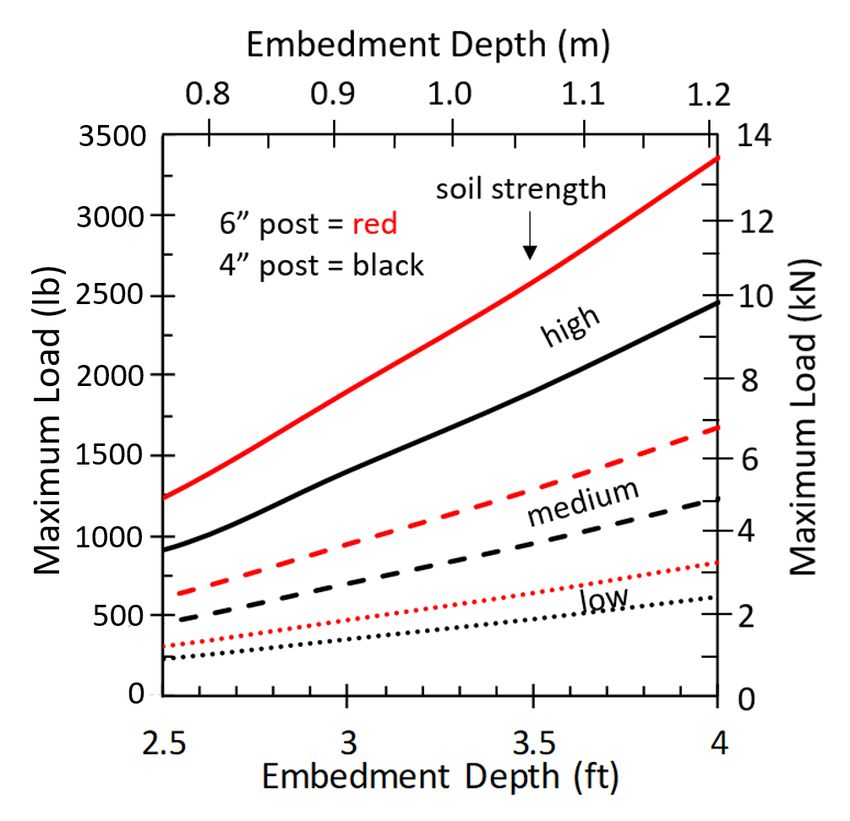
support wires
                                                                                        2’
                                       12.5 Ga. HT class 3 galvanized
              14’ posts
            6” diameter
          25 year warranty
                                                                                        2’

                                            8’ min. brace length                        2’

                     54”
                                                   25°
                                                max. angle                             3’

                                 6”

                                                                                        4’

                                 Figure 4 H-Frame end-post assembly.

The H-frame makes use of a horizontal cross-brace and a diagonal tension wire. The primary
purpose of the brace and diagonal tension wire is to distribute and share the trellis wire loads
between the two posts. This effectively doubles the holding capacity of the system versus a
single post of the same diameter and installation depth, making this system superior to the single
end-post design. Avoid notching posts. If posts are notched, treat with copper napthenate to
prevent rot.
The length of the posts above the brace will have sufficient capacity to withstand bending forces
from the trellis wires. It is the length of the posts below the ground that is the critical feature of
the H-frame system as this is where the soil must resist the over-turning of both posts.
The horizontal cross brace should be twice as long as the brace height above the ground. Most
orchards that use the H-frame system have been installing the cross-brace unnecessarily high
above the ground. The appropriate brace height is approximately 54” above the ground. This
height also facilitates safer and easier installation. With a 54” installation height, the brace
should be 9’ long, although an 8’ long brace can also be used. The purpose of the longer brace
and lower brace height is to ensure that the diagonal tension wire is kept at a shallow angle

                                                  6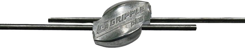
Support Systems for High-Density Orchards (2018)

(
~2’
                                    12’ post
                               4” to 6” diameter
                               25 year warranty                                    support wires
                                                              10%               2’ 12.5 Ga. HT
                                                              or 6°              class 3 galvanized

                                                                                2’

                                                    30°                 54”
                                                 max. angle
                                                                                3’

                                            8’
          >3’                                                                   3’

                 soil anchor

                               Figure 5 End-post with a tie-back soil anchor.

Alternatively, a 5/32” galvanized steel 7x19 cable can be used to connect the anchor to the post.
The tension in this cable should be approximately 1000 lbs. A GrippleTM DPAK connector is
very useful for completing the connection between the soil anchor and the post.
It is important to drive both the soil anchor and post to their full depths. If the soil strength is
poor, the following options can be used:
• drive the anchor deeper
• use a bigger anchor
• drive the post deeper, or
• use a larger diameter post.

2.6 Addition of an End-post to a Post with a Tie-Back
One issue with using a tie-back anchor at the end of the line of posts is that the anchorage
requires space that does not support trees and the anchorage impedes equipment travel around
the end of the trellis. A solution to overcome these limitations is to use the tie-back on the
second-last post along the trellis. In this manner, the anchorage does not get in the way of
equipment, and the full length of the orchard can be used to grow trees. A further advantage of
this end-post design is that the last post can also assist the tie-back post in carrying the trellis
wire loads. This design uses fewer post materials compared to the H-frame system and can
achieve greater capacity than an H-frame even when using smaller diameter posts. The greater
capacity comes from the soil anchor that is added to the two posts to carry a portion of the load.

                                                        8
Support Systems for High-Density Orchards (2018)
~20’
~2’
Install vertically Install vertically
or 6° off of 4 tensioned wires or 6° off of 2’
vertical vertical
2’
30° 54”
12’ posts
4” to 6” diameter max. angle
3’
25 year warranty
8’
3’ >3’ 3’
soil anchor
Figure 6 Combination of a tie-back post with an end-post.
When using an additional post beyond the tied-back post, the main trellis wires should still
terminate at the tie-back post. Four additional short tensioned wires are used to connect the tie-
back post to the end-post. The combination of different wires and the tie-back anchor allow for
fine-tuning of the tension in the various components of the trellis system.
The recommended installation sequence is:
• Install all posts along the line. Drive all posts 3’ deep. All posts can be vertical, or one or both
of the last two posts can be inclined 6° off of vertical.
• Install the soil anchor and connect the anchor to the tie-back post and lightly tension the
connection wire.
• Install the main trellis wires and terminate them at the tie-back post. Lightly tension these
wires.
• Tension the soil anchor connection wire to at least 500 lbs.
• Tension the main trellis wires to 250 lbs.
• Install the four short wires between the end-post and tie-back post and tension these wires to
150 lbs.
The addition of an end-post to a tie-back post is likely easier to construct than an H-Frame and
provides the equivalent or higher capacity to withstand the loads in the trellis wires.
92.7 Wire Spacing and Tension
A trellis makes use of posts to carry the wires, which in turn support the trees and their fruit. A
support system will typically use four high tensile strength (HT) wires strung between the posts.
The recommended wire to use is 12.5 gauge HT, galvanized (Class 3) steel wire.
The recommended maximum vertical wire spacing is 2’ with the lowest wire set approximately
3’ above the ground. The top wire can be attached to the top of the post, but the recommended
better practice is to attach it at least 4” from the top of the post. The lowest wire is also typically
used to carry irrigation lines. It is important that the trellis wires be tensioned to 250 lbs after
they are installed on the line of posts. The tension should be checked over the life of the trellis
system and adjusted if needed. Slack in the wires will cause underperformance of the system.
If possible, the length of a trellis wire should be kept less 500’ (150 m) to reduce end-post loads.
After the trellis is installed and the wires are stretched to the proper tension, a grounding wire
should be installed for lightning protection.
3 Soil Considerations
The soil beneath an orchard ultimately supports the trees and the trellis system. It is extremely
important to recognize the uniqueness of each orchard site. “Just because a trellis design worked
at your neighbour’s farm, doesn’t mean it will work at yours” (Fraser 2017). Soils in BC have
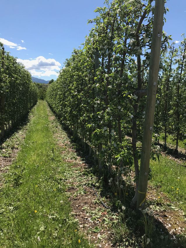
been mapped in many areas. Soil texture (see Figure 7), an important indicator of soil strength,
can vary significantly within only a few hundred metres.
Figure 7 Typical soil texture map.
It is ultimately the soil beneath an orchard that determines the carrying capacity and required
characteristics of a trellis system. Soils are classified by their three primary components: sand,
silt, and clay (Figure 8).
• Weaker soils, with less strength, will require closer post spacing, greater post depths, and more
complex end post systems.
10Support Systems for High-Density Orchards (2018)
• Rocky soils may inhibit the placement of posts, and require complex end post systems.
• Soil strength increases with the degree of compaction and bulk density.
• Wetter soils tend to be weaker. Soils with significant clay content can be relatively strong but
lose their strength when they become highly saturated.
• Poor drainage and moisture accumulation, especially in fine sand and silt soils can greatly
reduce soil strength.
• Flatter topography reduces the required strength and integrity of support systems.
Figure 8 Soil textures.
Table 1 lists the expected range of soil strength represented by the maximum lateral pressure that
can be applied to the side of a post, friction angle, and soil density. Approximate bearing
capacities for soils are also listed, and these indicate the effort needed to drive a post into the
ground. These properties can be used to estimate the required depths for wooden posts.
Table 1 Typical soil properties.
Lateral pressure per Friction Density Bearing
Soil type
unit depth (kPa/m) angle (kg/m3) capacity (kPa)
1440 -
Sandy gravel, and or gravel 31.4 -47.1 32° - 38° 100
1760
Sand, silty sand, clayey sand, 1360 –
23.6 -31.4 26° - 31° 70
silty gravel, and clayey gravel 1680
Clay, sandy clay, silty clay, and 1440 -
15.7 -20.4 12° - 25° 50
clayey silt 1920
Soil properties should be measured on site before designing and implementing a support system.
114 Trellis Components
4.1 Posts
Posts are the ‘trunks’ of an orchard support system. Posts provide support to the trees, fruit,
irrigation components, and to resist wind loads. They must last for the entire life of the planting,
typically (20 years).
Steel or concrete posts can be used, but the most common posts used in BC are treated
Lodgepole pine. Lodgepole pine posts have little taper and knots. Knots, splits, and high
moisture content will reduce a post’s strength. Choose posts with minimal knots and cracks. Pre-
select the best quality posts for end-posts. Pre-measure and mark posts for depth to ease
installation.
It is important to understand that posts are sold in size ranges spanning one inch and by the
minimum diameter. For example, a 4” diameter post has a minimum diameter of 4”, but over its
length, the diameter can taper from 4” to 5”. The minimum post diameter should be 4”
(100 mm).
The post diameter governs the load the post can withstand before it breaks. Figure 9 shows the
maximum force that a Lodgepole pine post can carry at a distance of 7’ above the ground. The
load capacity for a 6” post is 3.4 times higher than for a 4” post.
Post Diameter (mm)
100 125 150
4000
maximum
load 15
3000
Maximum Load (kN)
Maximum Load (lb)
7’
(2.1m) 10
2000
1000 5
0 0
3 4 5 6 7
Post Diameter (inches)
Figure 9 Upper and lower limits for the maximum force a Lodgepole pine post (12% moisture content)
can withstand before breaking.
Using posts smaller than specified in a trellis can seriously increase the risk of failure over the
life of the orchard (20 years).
The depth a post is embedded into the ground affects it’s resistance to over-turning by a force
applied to the post. Using the same load location shown in Figure 9, the maximum allowable
force before the post begins to over-turn for different embedment depths is shown in Figure 10.
This figure illustrates the importance of the soil strength. Strong soils provide much higher over-
12Support Systems for High-Density Orchards (2018)
turning resistance than weak soils. A comparison between Figure 9 and Figure 10 shows that the
post itself can typically handle the loads better than the soil. For example, a 4” line-post installed
3’ into medium strength soil can be pushed over with a force of 3 kN, whereas the post itself can
withstand 4 kN before it breaks. A single 6” end-post installed 4’ deep will not over-turn until
the load exceeds 6 kN, which is twice the value for a 4” post that is 3’ deep. A 6” post will not
break until the load exceeds about 12 kN. In these two examples, the soil is the limiting factor,
not the post, which emphasizes the need to ensure the posts are driven deep enough into the
ground.
Figure 10 Maximum allowable force applied at 7’ above the ground for a post installed at different depths
in soils with different strengths.
The major disadvantage with wooden posts is their susceptibility to rot and fungal decay. Fungal
rot destroys the cellulose in wood that provides its strength. Brown rot can reduce wood mass by
5 to 10% while being visually undetectable and reducing a post’s strength by 20 to 80%.
Referring to the examples presented earlier in the comparison between Figure 9 and Figure 10,
once the post experiences significant rot, the weakest component shifts from the soil to the post.
Wood maintained at less than 20% moisture will resist rot. Wood that is deep in the ground
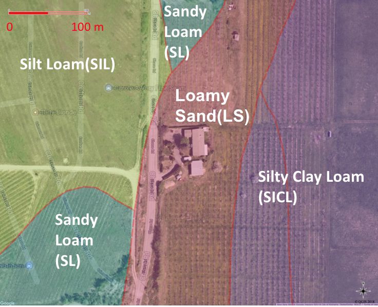
below the water table is less susceptible to rot due to low oxygen levels. The most critical
location for post rot is slightly above and approximately 0.3 m below the ground surface (Figure
11), where optimum conditions occur for fungal growth and rot. This is also the location where
the highest bending forces occur in the posts.
To maximize the life of a support system, the posts must be pressure treated with wood
preserving chemicals. While treated wood costs slightly more, pressure-treated posts greatly
reduce system maintenance and extend the support system life.
When purchasing pressure-treated posts, request posts that have been treated for 'ground contact'
conditions. Specifically, the posts should be treated with Chromated Copper Arsenite (CCA) to
the CSA O80 standard. Untreated Lodgepole pine posts have a life expectancy of only 4 to 12
years before being severely affected by rot. Cedar posts can be expected to provide 20 or more
years of service without deterioration. When treated to the CSA O80 standard and subjected to
13normal weather conditions with some exposure to freshwater, Lodgepole pine posts should be
good for more than 25 years. If in doubt whether the posts have been treated to the standard,
check the warranty provided by the supplier. Posts treated to the CSA O80 standard should be
warranted for at least 25 years. Currently, CSA O80 pressure treated Lodgepole pine posts are
available in diameters up to 8-9”, nominally 8”, and up to 39’ in length.
typical rot
zone
Figure 11 Rot zone for wooden posts.
If posts are cut during installation, the freshly exposed wood should be brushed with copper
napthenate. Allow one week for the treatment to dry before using the posts or for planting trees
near the posts.
Certified organic standards do not currently permit the use of treated wood posts. In this case,
cedar posts are recommended as an alternative. Note that Western red cedar has approximately
70% of the strength of Lodgepole pine. Thus larger 5 to 6” post diameters are recommended
everywhere in a trellis system constructed with cedar posts.
4.2 Wire
The use of high tensile strength wires is the primary means of transferring loads from trees to
posts via staples and fasteners. Wires carry the weight of the trees, the fruit crop, and anything
attached to the trees or exerting forces on them, including wind. In BC, the commonly available
wire for the construction of trellises for tree fruits and grapes include:
• 14 Ga galvanized in 5858 ft rolls (imported)
• 12 Ga galvanized in 3750 ft rolls (imported)
• 12.5 Ga galvanized in 3750 ft rolls (domestic)
It is strongly recommended that the 12.5 Ga (domestically produced) wire with Class 3
galvanizing be used. Research indicates this wire seldom breaks and relative additional cost to
alternatives is negligible. This wire has a breaking strength of 1380 lbs and is ideal for orchard
support systems because it provides adequate strength while minimizing exposure to corrosion
over the life of the planting (20 years). In use, it should be tensioned to 250 lbs.
Class 3 galvanizing provides significantly more protection than Classes 1 and 2. Class 3
galvanizing is the preferred standard to provide long-term protection from corrosion. With this
14Support Systems for High-Density Orchards (2018)
corrosion protection, rust should not appear on the wire in the first 13 years under humid
conditions, and it will take more than 50 years before the wire strength reduces by 50%.
When installing the wire, do not kink the wire as this weakens it. Carefully roll the wire off the
rolls using a Spinning Jenny. Do not lay the roll of wire on the ground and pull the wire off the
roll. If the wire is not removed from the roll opposite to the way it was rolled on, the wire will
become distorted and may kink.
To make splices in HT wire, use 3 sleeves. Slide all 3 sleeves onto one wire. Thread the second
wire to be spliced through the other side of the sleeves. Overlap wires so there is enough space
on the wires for all 3 sleeves. Use a crimping tool to crimp the sleeves closed.
4.3 Staples
The trellis wires are typically connected to the posts with staples.
Another option is to drill a 3/8” diameter hole through the posts at
the desired height and run the wire through the holes.
Staples are available in different sizes, but 2” staples with double
barbs, slashed ends and Class 3 galvanized coating should be used
(Figure 12). They are only marginally more expensive than
alternatives but provide greater penetration depth into posts and
better holding capacity. Figure 12 Double barbed galvanized
staple.
Staples should be driven such that a small gap remains between
the trellis wire and the crown of the staple. This prevents
kinking and strength loss in the HT wire. Leaving a slight gap
also allows the wire to slide beneath the staple to better
redistribute loads in the wire. Hold wires against the post when Angle staple to
Support wood grain for
driving in staples to prevent damage to the wires. Staples should
wire max. strength
also be driven at an angle into the grain of the wood, not
vertically (Figure 13).
For posts on top of a hill, the tension in the wire will pull the
staples down, thus angle the staples slightly upward when
driving them into the post. For posts in a low area, the wire will
pull the staples upward, thus angle them downward. Use two
staples for each wire in both cases. Figure 13 Drive staples at an angle to
wood grain.
If posts are drilled to pass the wire through, then ensure holes
are drilled straight and level to minimize interference with the trellis wires. Posts with holes are
not recommended for use in hilly ground where wires can pull up or down and cut into posts and
weaken them.
Mount support wires on the windward side of posts to maximize support in windy conditions.
There is no agreement on which side of supporting wires trees should be on. Trees on the
windward side have more support and are more forgiving of tree connectors. Trees on the
leeward side have less support but are also less subject to trunk bruising.
154.4 Wire Connection, Termination, and Tensioning
Supplemental hardware exists to ease the construction of an orchard support system, particularly
in splicing and joining wires and in anchoring to the ground. Growers should refer to their
suppliers for available supplemental hardware and should take the time and effort to ensure that
they know how to properly and safely use the tools.
Each high tensile strength wire must be terminated at the
end-post. Different options exist for terminating the wires.
Twisting and tying the high tensile strength wire is not
recommended as this can significantly reduce the tensile
strength of the wire. The simplest termination option
consists of using double-barrel wire crimp sleeves (Figure
14). The wire is inserted through two crimping sleeves and
then wrapping twice around the post. The dead end of the
wire is then inserted through the other half of the two Figure 14 High-tensile wire sleeve.
crimping sleeves and crimped into place. This option does
not permit for adjustment of the wire tension, and thus the
wire will need to be tensioned and terminated differently at
the other end, or an in-line wire tensioning device will need
to be used.
A ratcheting wire strainer (Figure 15) can be attached near
the post to provide a wire tensioning when using crimping
sleeves. The end of the ratchet is attached to the post using
a loop of 12.5 gauge HT wire and two crimping sleeves.
For a trellis length less than approximately 500’, the
ratcheting wire strainer only needs to be placed at one end
of the wire run. If the trellis length is greater than 500’,
placing the ratcheting wire strainer in the middle of the wire
run permits better tensioning over the full length of the Figure 15 Ratcheting wire strainer.
trellis.
For wire lengths less than roughly 250’, an adjustable
termination can be achieved by drilling a 3/8” diameter hole
through the post, running the wire through the hole and then
through a one-way steel wire vise (Figure 16). The locking
portion of the vise is forced into the hole when the wire is
tensioned. As long as a sufficient length of the wire remains
protruding beyond the wire vise, this termination method
allows for further tensioning if needed. Thus it is good
practice to leave a small length of wire sticking out of the
vise. Bend the end of the wire over and pushed into a small Figure 16 One-way wire vise.
hole in the post or staple it to the post to safely hide the
sharp end of the wire.
16Support Systems for High-Density Orchards (2018)
An option for controlling the tension in long runs
(>500’) of wire is to use an in-line wire tensioner
(Figure 17) placed roughly mid-way along the wire.
A quick and flexible termination option that allows for
adjustable tensioning of the HT wire is the use of a
medium size GrippleTM self-locking wire connector
(Figure 18). The HT wire is inserted through one Figure 17 In-line wire tensioner.
opening in the connector and wrapped around the post,
and the dead end of the wire is inserted through the
second opening in the connector and tensioned. The
connector should be spaced approximately 2’ from the
post. The wire can be re-tensioned if needed using the
Gripple Torq tensioning tool. If the trellis length is Figure 18 Medium size GrippleTM
greater than 500’, it is best if a GrippleTM self-locking connector.
wire connector is used at both ends of the wire to
ensure proper tensioning of the wire along the full
run length.
Orchardists should also invest in a wire tensioning
tool, for example, a Gripple Torq tensioning tool
(Figure 19) can be used to assure proper tension is
maintained in the trellis wires. This tool can apply up
to 600 lbs tension in the wire.
4.5 Soil Anchors
The two general types of soil anchors can be used to
secure tie-back wires/ropes (Figure 20). One type
consists of a helical steel plate welded onto the end of a
steel rod. The anchor is installed by applying a torque to Figure 19 Gripple Torq tensioning tool.
the rod, which screws the helix into the soil. The other
type consists of a harpoon-like device that is driven into the soil. The ‘harpoon’ is attached to a
steel wire rope, and when the rope is placed under tension, the harpoon rotates within in the soil
to lock the rope.
Both anchor types should be installed greater than 40” (1 m) into the ground. Ideally, each soil
anchor should be installed in firm undisturbed soil at an inclination (see Figure 6) such that the
wire rope or anchor shank to points towards the tie-back attachment location on the end port. The
attachment loop should be near the ground surface after the anchor is installed.
Screw-in anchors should have a 5” to 6” (12.5 to 15 cm) diameter helix welded to a ¾” (19 mm)
diameter shaft with a heavy eye ring for the wire or rope attachment. A 6” diameter helix should
have a holding capacity of 4000 lbs (20 kN) in most soil types.
A popular harpoon type soil anchor is the Gripple TM anchor. The larger #4 Gripple TM anchor
should be used along with an anchor cable that is least 5/32” in diameter. A 5/32” galvanized
steel 7x19 cable typically has a breaking load of approximately 2600 lbs. A #4 anchor should
have a holding capacity of 1000 to 4000 lbs depending on the soil type.
17Figure 20 Harpoon and screw type soil anchors.
A double-loop of 12.5 Ga. HT wire can be used to connect the tie-back post to the soil anchor.
This wire should wrap around the post and run through a wire rope thimble or steel eye at the
soil anchor. This wire will form two continuous tensioned loops. Thus the loads are carried in
four wires between the post and soil anchor. It is important to install the wire with a relatively
high tensile load of approximately 500 lbs. Alternatively, a 1/4” steel wire rope in a single loop
can be used to connect the end post to the soil anchor.
5 Trellis Maintenance
Once installed and established, orchardists should periodically exercise maintenance to assure
the integrity of the trellis system over its entire life. Ideally, the followed should occur annually:
• The tension in the trellis wire should be periodically checked and adjusted if necessary to
maintain a load of 250 lbs (1.1 kN) when the wire is carrying fruit loads. The wire tension
should be reduced before winter to accommodate thermal contraction of the wire under cold
temperatures.
• Check for loose staples and add new ones as necessary, especially for hilly ground.
• Inspect the end posts to ensure they have not loosened or experienced unexpected rot. End
posts should be replaced if they are damaged.
• Limit leader growth to 1’ above the top wire to minimize breakage adversely affecting tree
structure and performance. Annually, remove large side branches near the leader to avoid
heavy crop loads above the top wire.
18Support Systems for High-Density Orchards (2018)
Acknowledgements
Project leader: Keith Duhaime P.Ag.
With assistance from the School of Engineering, University of British Columbia – Okanagan:
• Dwayne Tannant P.Eng.
• Christian Desjarlais
• Lukas Vozeniluk
Project guidance and assistance:
• Tony Di Maria, BC Tree Fruits Cooperative
• Hank Markgraf, BC Tree Fruits Cooperative
• Carl Withler P.Ag., BC Ministry of Agriculture
Additional assistance:
• Ivan Campos, Pacific Northwest, Gripple Inc.
• Elizabeth Marion, Princeton Wood Preservers
• Ron Pattermann, Grower’s Supply Co. Ltd.
Funding
Funding for this project has been provided by Agriculture and Agri-Food Canada and the BC
Ministry of Agriculture through the Canada-BC Agri-Innovation Program under Growing
Forward 2, a federal-provincial territorial initiative. The program is delivered by the Investment
Agriculture Foundation of BC.
Disclaimer
Agriculture and Agri-Food Canada (AAFC) and the BC Ministry of Agriculture are committed
to working with industry partners. Opinions expressed in this document are those of [the authors]
and not necessarily those of AAFC, the Ministry of Agriculture, or the Investment Agriculture
Foundation.
19References
This manual incorporated material from the following sources.
AAFC. (n.d.). Canadian System of Soil Classification, 3rd edition. Ch. 17: Terminology of Describing
Soils. Agriculture and Agri-Food Canada. (http://sis.agr.gc.ca/cansis/taxa/cssc3/chpt17.html)
ANSI/ASAE. (1999). Shallow Post Foundation Design EP486.1.
ASABE (2012). Shallow Post and Pier Foundation. American Society of Agricultural and Biological
Engineers. EP486.2.
BC Ministry of Agriculture. (n.d.). Okanagan – Agricultural Land Use Inventory Projects.
(https://www2.gov.bc.ca/gov/content/industry/agriculture-seafood/agricultural-land-and-
environment/strengthening-farming/planning-for-agriculture/agricultural-land-use-
inventories/okanagan)
British Columbia Ministry of Agriculture. (2015). Fencing Factsheet. Abbotsford.
CSA. (2015). CAN/CSA-O80 Series-15, Wood preservation. Canadian Standards Association.
CWC, Canadian Wood Council. (n.d.). Durability by Treatment, About Treated Wood.
(http://cwc.ca/design-with-wood/durability/durability-solutions/durability-by-treatment/)
De Kleine, M., P.E. Booker, K. Lewis and C. Pezeshki. (2017). Engineering Analysis for High Density
Trellis Structures.
(http://jenny.tfrec.wsu.edu/wtfrc/PDFfinalReports/2017FinalReports/DeKleineTrellisFINAL.pdf)
Fraser, H. (2017). Trellis Support Systems for High-Density Apples. Proceedings from the Empire State
Producers Expo Syracuse, NY. January 17-19, 2017.
(http://www.hort.cornell.edu/expo/proceedings/2017/TreeFruit%20Weather.%20Trellis%20Support%
20Systems%20for%20High-Density%20Apples.pdf)
Kretschmann, D.E. (2012). Mechanical Properties of Wood. In R. J. Ross, Wood Handbook - Wood as an
Engineering Material (pp. 5-1 to 5-44). Madison, WI: United States Department of Agriculture, Forest
Service, Forest Products Laboratory.
Lehnert, R. (2010). High density apple systems cost more, but profits are larger and happen sooner. Good
Fruit Grower. August. 1, 2010. (http://www.goodfruit.com/high-density-apple-systems-cost-more/)
OAG. (2015). Best Management Practices for Building Trellis Support Systems for High Density Ontario
Apples. Ontario Apple Growers. (http://www.onapples.com)
Public Services and Procurement Canada. (2015). Organic production systems – General principles and
management standards (CAN/CGSB-32.310-2015). ( http://www.tpsgc-pwgsc.gc.ca/ongc-
cgsb/programme-program/normes-standards/internet/bio-org/pgng-gpms-eng.html)
Tsair-Bor, Y. (2004). Assessment of the Mechanical Properties of Lodgepole Pine in the Incipient Stage
of Decay by a White-Rot Fungus. Ann Arbor, MI: ProQuest Information and Learning Company.
U.S. Steel. (1982). How to build an orchard and vineyard trellises. U.S.S. Catalogue No. T-111578,
Pittsburg.
van Delfsen, K.B. (1989). Support Systems for High-Density Orchards. Province of British Columbia. BC
Ministry of Agriculture and Fisheries.
20SUPPORT SYSTEMS for HIGH-DENSITY ORCHARDS (2018)
For more information, contact:
BC MINISTRY OF AGRICULTURE
1690 POWICK ROAD
KELOWNA, BC V1X 7G5
Tel. (250) 861-7211
Funding for this manual was provided by:You can also read