PHYSICAL REVIEW FLUIDS 6, 044301 (2021) - Numerical study of suspensions of nucleated capsules at finite inertia
←
→
Page content transcription
If your browser does not render page correctly, please read the page content below
PHYSICAL REVIEW FLUIDS 6, 044301 (2021)

      Numerical study of suspensions of nucleated capsules at finite inertia

                      Arash Alizad Banaei, Armin Shahmardi, and Luca Brandt
Linné Flow Centre and SeRC (Swedish e-Science Research Centre), Department of Engineering Mechanics,
                   Royal Institute of Technology (KTH), S-100 44 Stockholm, Sweden

                   (Received 13 May 2019; accepted 15 March 2021; published 6 April 2021)

            We study the rheology of suspensions of capsules with a rigid nucleus at negligible and
         finite flow inertia by means of numerical simulations. The capsule membrane is modeled
         as a thin Neo-Hookean hyperelastic material and the nucleus as a rigid particle with radius
         equal to half the radius of the undeformed spherical capsules. The fluid and solid motion are
         coupled with an immersed boundary method, validated for both the deformable membrane
         and the rigid nucleus. We examine the effect of the Reynolds number, capillary number, and
         volume fraction on the macroscopic properties of the suspensions, comparing with the case
         of capsules without nuclei. To explain the rheological measurables, we examine the mean
         capsule deformation, the mean orientation with respect to the flow direction, and the stress
         budget. The results indicate that the relative viscosity decreases with the capillary number,
         i.e., increasing deformability, and increases with inertia. The presence of a nucleus always
         reduces the membrane deformation. Capsules align more in the flow direction at higher
         capillary numbers and at higher volume fractions, where we also see a significant portion of
         them oriented with their longer deformed axis in the spanwise direction. When increasing
         inertia, the alignment with the flow decreases while more capsules orient in the spanwise
         direction. The first normal stress difference increases with the capillary number and it is
         always less for the nucleated capsules. Finally, the relative viscosity and the first normal
         stress difference increase with the capsule volume fraction, an effect more pronounced for
         the first normal stress difference.

         DOI: 10.1103/PhysRevFluids.6.044301

                                           I. INTRODUCTION
   The rheological properties of capsule suspensions have great importance in medical applications,
as well as in process industry. Capsules are defined here as droplets of a second fluid enclosed by
a thin elastic membrane, transported and flowing in a carrier phase. Typically, capsules conserve
volume while, unlike vesicles, their surface area can vary during the flow as a result of flow-induced
deformations. As a classic example, because of the presence of the deformable red blood cells,
blood is typically modeled as a suspension of deformable capsules and therefore characterized by a
non-Newtonian viscoelastic behavior. The rheological properties are highly correlated to the mem-
brane elasticity and to cell-cell interactions in denser conditions; see, among others, Reasor et al.
[1]. In particular, the two main distinctive characteristics of the viscoelastic behavior—the relative
viscosity as a function of the applied shear and the normal stresses—have been found to depend
both on the average capsule deformation and on the capsule orientation angle; see, e.g., the recent

Published by the American Physical Society under the terms of the Creative Commons Attribution 4.0
International license. Further distribution of this work must maintain attribution to the author(s) and the
published article’s title, journal citation, and DOI. Funded by Bibsam.

2469-990X/2021/6(4)/044301(22)               044301-1             Published by the American Physical Society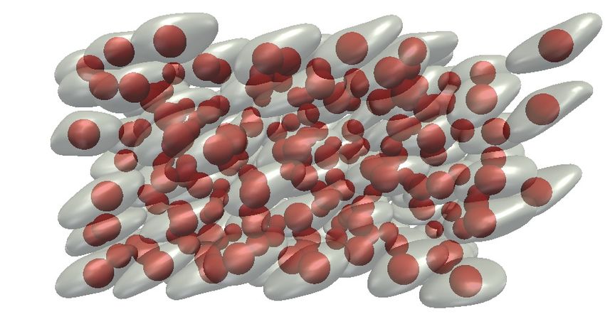
ALIZAD BANAEI, SHAHMARDI, AND BRANDT

study by Matsunaga et al. [2]. Here, we study capsule suspensions as a model of cells in simple
shear flows including the inertial regime and considering an additional complexity: the presence of
a rigid nucleus. As shown here, the global suspension behavior is affected by the presence of the
rigid nucleus inside the capsules, which we use to model, as examples, malaria-infected blood cells
or eukaryotic cancer cells [3].
    An expression for the relative viscosity of capsule suspensions has been derived analytically by
Barthes-Biesel and Chhim [4] in the limit of small capillary numbers, predicting a shear-thinning
behavior for dilute suspensions. The rheology of concentrated suspensions of viscoelastic particles
was studied by Snabre and Mills [5] using an analytical Kelvin-Voigt model. These authors report
shear thinning at high volume fractions while the effective viscosity was found to be almost
independent of the shear rate at lower volume fractions. With regard to numerical studies, a
coupled lattice-Boltzmann and finite-element method was proposed by MacMeccan et al. [6]
for the simulation of deformable particles, enabling efficient simulations of suspensions at high
volume fractions. These authors consider initially spherical and biconcave capsule suspensions at
40% volume fraction, and they report a significantly lower viscosity for initially spherical capsule
suspensions, both suspensions displaying shear-thinning behavior.
    The rheology of dilute capsule suspensions has been studied using three-dimensional numerical
simulations by Bagchi and Kalluri [7], where the role of the viscosity contrast between the fluid
inside and outside of the capsules is also examined. These authors observe shear thinning and a
nonmonotonic variation of the relative viscosity with the viscosity ratio. The effect of the swinging
and tumbling motions of initially oblate capsules on the rheological properties of dilute suspensions
is investigated in Ref. [8], again by means of numerical simulations, showing that unlike spherical
capsule suspensions, the system response is clearly time-dependent while the time-averaged rheo-
logical properties are qualitatively similar to those of suspensions of spherical capsules. A numerical
study of the dynamics and microstructure of dense capsule suspensions is presented by Clausen et al.
[9]; those authors find that the first normal stress difference undergoes a sign change at relatively
small deformations. Dense suspensions of red blood cells have been investigated numerically in
Ref. [1], where it was found that the viscosity is dependent on the orientation and bending modulus
of the cells and that the normal stress tensor is characterized by a transition from compressive to
tensile states in the flow direction when increasing the shear rate. In addition, it is shown that the
bending stiffness and the initial shape of the capsules have a significant effect on the first normal
stress difference. Krüger et al. [10] investigated the role of flow inertia on the rheology of semidilute
capsule suspensions with a finite-element immersed-boundary lattice-Boltzmann solver, concluding
that for low capillary numbers there is a monotonic increase of the shear viscosity with the flow
inertia, whereas for larger capillary numbers the viscosity first increases and then decreases when
further increasing the flow inertia.
    The behavior of dense biconcave capsule suspensions is studied numerically by Gross et al.
[11] by varying the volume fraction up to 90%. These authors observe very large viscosity and
first normal stress differences at high volume fractions while the suspensions maintain their shear
thinning behavior; the Herschel-Bulkley rheological curves are used to fit these data. A multiscale
numerical study on blood flow was performed by Fedosov et al. [12], who considered red blood
cell suspensions in tubes with different diameters and reported a large increase of the relative
viscosity when decreasing the tube diameter. Recent theoretical and numerical results on the
rheological behavior of polymeric semi-dilute soft colloid, vesicle, capsule, and cell suspensions
are reviewed in Ref. [13], which mentions, among other things, that the viscosity is much larger for
aggregating cell suspensions than for nonaggregating cells. Matsunaga et al. [2] recently performed
an extensive numerical study on the rheology of dense suspensions of initially spherical capsules
with volume fractions up to 40%. They observe that unlike rigid spheres, the relative viscosity
increases almost linearly with the volume fraction even at high volume fractions in the case of
deformable capsules. In addition, the capsule deformation increases when increasing the volume
fraction while the mean capsule angle with respect to flow direction decreases, and this reduction
causes larger stress anisotropy, resulting in larger first normal stress differences. Rosti et al. [14,15]

                                                044301-2
NUMERICAL STUDY OF SUSPENSIONS OF NUCLEATED …
have investigated suspensions of deformable particles in the case of negligible inertia, reporting an
increase of viscosity with the particle volume fraction and shear thinning with deformability, i.e.,
increasing the capillary number. In addition, they report a peak of the first normal stress difference at
moderate capillary numbers. The data for the effective viscosity are shown to collapse to a universal
function by defining an effective volume fraction lower than the nominal one due to the particle
deformation. A similar scaling was confirmed by simulations of the rheology of deformable red
blood cells in dilute, semidilute, and dense suspensions [16].
All works discussed so far have considered simple capsules, without any rigid structure inside.
Malaria-infected red blood cells and eukaryotic cells, on the other hand, have a nucleus inside the
external membrane, which can significantly affect the capsule dynamics in a flow. The dynamics of
malaria-infected red blood cells have been studied in Ref. [17] by means of numerical simulations;
the results show a large increase of the relative viscosity in a microcircular channel with a diameter
of 12 μm in the presence of a sick cell in the trophozoite stage, where the size of the nucleus is of the
order of 20% of the cell. Spherical and nonspherical nucleated capsules in shear flow have also been
investigated numerically by Luo et al. [18] and Luo and Bai [19], who found that the inner nucleus
can significantly change the outer capsule dynamics, and that the size of the inner capsule, which
is used to mimic a stiff nucleus, strongly affects the overall dynamics. Single nucleated capsules
in shear flow are also simulated in Ref. [20], showing that the presence of the nucleus reduces the
capsule deformation, and that inertial effects do not have significant effects on the deformation of
isolated nucleated capsules. The motion of single nucleated capsules in a constricted microchannel
has been studied recently by Gounley et al. [3], who also report lower deformation for nucleated
capsules. All of these studies focus on single cells; no studies on the behavior of the nucleated cell
suspensions are available as of yet.
The goal of the present study is therefore to extend our previous work on the dynamics of a
single nucleated capsule [20] to suspensions of initially spherical capsules with nucleus and study
the rheological behavior and the capsule deformation at negligible and finite flow inertia, comparing
the results to those pertaining to suspensions of simple capsules. The same numerical setup used in
Ref. [20], where the nucleus is considered as a rigid particle, will be employed. The ratio between
the nucleus and the undeformed capsule diameter will be kept constant while examining the role
of the capillary number, Reynolds number, and volume fraction on the relative viscosity, first
normal stress difference, mean deformation, mean orientation, and elastic energy of simple and
nucleated capsule suspensions; in particular, the relationship between the rheological properties and
the deformation and orientation angle of the capsules will be discussed.
II. GOVERNING EQUATIONS AND NUMERICAL METHOD
The geometrical configuration adopted is depicted in Fig. 1. We consider a suspension of N
initially spherical capsules of radius R in a shear flow with top and bottom walls moving in opposite
directions imposing a shear rate γ̇ . The fluids inside and outside the capsules have the same viscosity
μ and density ρ in order to focus on the effect of elasticity and inertia. In the case of nucleated
capsules, the nucleus is modeled as a rigid spherical particle of radius 0.5R, initially located at the
center of each capsule and free to move inside it.
A. Governing equations
The dynamics of an incompressible Newtonian fluid are governed by the momentum and
continuity equations:
∂ ∂ui ∂ui ∂P 1 ∂ 2 ui
(ui ) = 0, + uj =− + + fi , (1)
∂xi ∂t ∂x j ∂xi Re ∂x j 2
044301-3ALIZAD BANAEI, SHAHMARDI, AND BRANDT
u1
x2
x1
u1
FIG. 1. Nucleated capsules in shear flow. The visualization refers to a suspension with volume fraction
φ = 31.42%.
where ui is the velocity vector, P is the hydrodynamic pressure, Re = ρ γ̇μR is the Reynolds number,
2
with R the initial radius of the capsules, τi j the fluid shear stress tensor, and fi represents here the
elastic forces arising from the interactions with the capsule membrane.
B. Capsule dynamics
The capsule membrane is modeled as a hyperelastic two-dimensional material, i.e., with thick-
ness much smaller than the capsule initial radius, and the same density as the fluid, which implies
that the relative acceleration of the membrane with respect to fluid is negligible. A fixed Cartesian
coordinate is considered for the fluid and capsule motion while a moving curvilinear coordinate
system is needed to represent the capsule deformation. As shown in Fig. 2, the fixed Cartesian
coordinates (x1 , x2 , x3 ) are defined by the Cartesian based vectors (e1 , e2 , e3 ), whereas the second
coordinate system (ξ 1 , ξ 2 ), which represents the points on the surface of the capsule, is a local
covariant base (a1 , a2 , a3 ). Each point on the capsule surface is represented in both coordinate
systems, X (ξ 1 , ξ 2 ) = (x1 , x2 , x3 ).
Two of the covariant base vectors are tangential to the curves of constant ξ α , aα = Xα , α = 1, 2,
with the third normal to the first two base vectors. Here, the subscript α indicates derivative with
respect to ξ α . Also, in this study, vectors and metric tensors in the reference state are shown in
capital letters. Assuming ξ 1 and ξ 2 as the latitudinal and longitudinal angles on the surface of the
a3
a2 a1
e2
e3 e1
FIG. 2. Schematic of a deformed capsule and Cartesian and curvilinear base vectors.
044301-4NUMERICAL STUDY OF SUSPENSIONS OF NUCLEATED …
capsule, one can write the three covariant base vectors as
∂X ∂X a1 × a2
a1 = , a2 = , a3 = . (2)
∂ξ 1 ∂ξ 2 |a1 × a2 |
The contravariant base vectors, (a1 , a2 , a3 ), are
aα aβ = δβα , (3)
where δβα is the Kronecker delta. Any arbitrary vector U can be written in both coordinates,
U = ui ai = ui ai = U xi ei , (4)
where xi stands for the Cartesian components. The metric tensors are defined as
aαβ = aα · aβ .
aαβ = aα · aβ , (5)
α
The deformation gradient tensor is defined as F = aα A , and consequently the Green-
Lagrange strain tensor is e = (FT · F − I)/2. The invariants of the transformation are
I1 = λ21 + λ22 − 2, I2 = λ21 λ22 − 1 = Js2 − 1, (6)
where λ1 and λ2 are the principal stretch ratios. The membrane is assumed here to behave as a
Neo-Hookean material, whose strain energy W NH s is defined in nondimensional form as a function
of the deformation invariants as
1 1
WsNH = I1 − 1 + , (7)
2 Re Ca I2 + 1
where Ca is the capillary number defined as the ratio of viscous forces to elastic forces,
μγ̇ R
Ca = , (8)
Gs
with Gs the surface shear modulus. The Cauchy stress tensor T , the elastic stress, can be obtained
from the strain energy:
2 ∂W NH ∂W NH
T αβ = s
Aαβ + 2λ1 λ2 s
aαβ . (9)
λ1 λ2 ∂I1 ∂I2
The deformation of a neutrally buoyant membrane (no density difference with the fluid), for
which inertia can be neglected, is determined by the local equilibrium between the external load
and the elastic stresses:
∇s T + q = 0, (10)
where ∇s is the surface divergence operator. To express this equation in curvilinear coordinates, we
write the load vector as q = qβ aβ + qn an , and we decompose Eq. (10) into tangential and normal
components:
∂T αβ α λβ β
+ αλ T + αλT αβ + qβ = 0, β = 1, 2, T αβ bαβ + qn = 0,
∂ξ α
β
where αλ = aα,λ aβ is the Christoffel symbol. In the case of a membrane with nonzero bending
stiffness, the bending moment and shear tension should also be considered [20,21].
This is incorporated into the model using a linear isotropic model for the bending moment as a
function of deformation [21,22]:
−B̃ α
Mβα = bβ − Bβα , (11)
We
044301-5ALIZAD BANAEI, SHAHMARDI, AND BRANDT
where B̃ = GGs Rb 2 is the nondimensional bending modulus and bαβ = aα,β · n is the second fundamen-
tal form of the surface (Bβα refers to that of the reference configuration). According to the local
torque balance, including bending moments on the membrane, the transverse shear vector Q and
in-plane stress tensor T can be obtained as
αβ
M|α − Qβ = 0, εαβ T αβ − bαγ M γ β = 0, (12)
where ‘|α ’ represents the covariant derivative, and ε is the two-dimensional Levi-Civita tensor. The
left-hand side of Eq. (12) identifies the antisymmetric part of the in-plane stress tensor, which
is always zero as proven in Ref. [23]. Including the transverse shear stress Q, the local stress
equilibrium, including bending, finally gives
∂T αβ α λβ β αλ
+ αλ T + αλ T − bβα Qα + qβ = 0, β = 1, 2, T αβ bαβ − Q|α
α
+ qn = 0. (13)
∂ξ α
C. Numerical method
The flow equations are solved by a fractional step method on a uniform grid; see more details
in Refs. [20,24] and in previous studies on suspensions of rigid particles [24–26]. The momentum
equations are solved by the finite volume method using central differences for the spatial discretiza-
tion. For the temporal integration, the Adams-Bashforth scheme is used for the convective terms
while the diffusive terms are treated implicitly. The reader is referred to our methodology paper
[20] for further details.
To solve the fluid solid interactions, we use the immersed boundary method (IBM), which was
first introduced by Peskin [27]. Since then, different IBM approaches have been proposed, suited
for simulating different physical problems; see, e.g., the review by Mittal and Iaccarino [28]. In this
study, the original method proposed by Peskin [27] is implemented for the capsule motion, while a
direct forcing IBM is used for the rigid particles [24]. As in a classic IBM, two sets of grid points are
considered, namely an Eulerian and a Lagrangian grid, which are linked by the fluid-solid interaction
force, corresponding to the elastic stresses in our case. As the details are provided in Ref. [20], we
report here directly the solution steps, which can be summarized as follows:
(i) Solve the flow field on the Eulerian mesh.
(ii) Interpolate the solution velocity field onto the Lagrangian grid points, discretizing Eq. (14)
using the approximated Dirac delta function, δ, first proposed by Roma et al. [29],
Uib (X, t ) = u(x, t )δ(X − x)dx, (14)
where x and X are the Eulerian and Lagrangian coordinates.
(iii) Calculate the tangential and normal vectors on the Lagrangian elements and the elastic force
per unit area by solving for the membrane dynamics.
(iv) Spread the elastic force onto the Eulerian mesh by the same Dirac δ function proposed by
Roma et al. [29],
f (X, t ) = −q(X , t )δ(x − X )ds. (15)
(v) Solve the Navier-Stokes equations for the flow field, updating the fluid-structure interaction
force.
(vi) Update the positions of the Lagrangian points,
X n+1 = X n + Uib n t, (16)
where t is the time step.
These operations are performed each time step. Following the work by Pranay et al. [30], an
extra displacement correction is imposed on the Lagrangian points at every time step to ensure the
044301-6NUMERICAL STUDY OF SUSPENSIONS OF NUCLEATED …
volume conservation for the capsules,
−3(V − V0 )
z= n, (17)
A
where V and V0 are the instantaneous and initial volumes, A is the capsule surface area, and n is the
unit normal to the capsule surface area.
To compute the elastic stresses, derivatives on the capsule surface are needed; for an accurate
discretization, the capsule shape is represented by a truncated series of spherical harmonic functions,
SH −1
N n
m
x(ξ 1 , ξ 2 ) = Pn (cos ξ 1 )[anm cos(mξ 2 ) + bnm sin(mξ 2 )], (18)
n=0 m=0
2 m
with NSH the total number of spherical harmonics. Pn (x) is the normalized Legendre polynomial,
m 1 (2n + 1)n − m)! m d n+m
n
Pn (x) = (1 − x 2 ) 2 n+m (x 2 − 1) . (19)
2n n! 2(n + m)! dx
In spherical coordinates, the domain is discretized on a quadrilateral grid using Gauss-Legendre
(GL) quadrature intervals in 0 ξ 1 π and uniform spacing in 0 ξ 2 2π .
In the case of nucleated capsules, we model the nucleus as a rigid particle using the direct-
forcing immersed boundary method proposed by Breugem [31] and later used, among others, in
Refs. [24,31,32]. Further details are therefore not provided here.
To avoid capsule-capsule, capsule-particle, and capsule-wall overlapping, needed at finite
Reynolds numbers, we use a repulsive force in the form of a Morse potential [33]. This is activated
when the distance between two surfaces becomes lower than two grid cells. The general form of the
potential is
ζ = De [e−2a(rL −re ) − 2e−a(rL −re ) ], (20)
where De is the interaction strength, a is a geometrical scaling factor, rL is the distance between two
surfaces, and re is the zero cutoff force distance, which is two grid cells here. The repulsive force
is the derivative of the potential F = − ∂ζ d , where d r is the unit vector between the two surfaces.
∂r r
The contact force computed at each Lagrangian point is spread to the Eulerian mesh and added in
the momentum equation, as shown in Eq. (15).
III. PROBLEM DESCRIPTION AND CODE VALIDATION
A. Problem description
To study the rheology of the nucleated and denucleated capsules, we consider the steady shear
flow between two moving walls. The dimensions of the channel in the streamwise, wall normal,
and spanwise directions are 16 × 10 × 16 in units of the undeformed capsule radius R, following
Refs. [34,35]. The flow is assumed to be periodic in the streamwise and spanwise direction, whereas
the upper and lower wall have the same velocity magnitude and opposite direction, a classic Couette
flow.
The domain is discretized with 256 × 160 × 256 grid points in the streamwise, wall-normal, and
spanwise directions, respectively. The capsule surface is typically represented with 36 × 72 points
in the latitudinal and longitudinal directions, corresponding to 2592 Lagrangian points on each
capsule surface and to 1296 spherical harmonics and 36 modes to resolve the capsule deformation.
For a few cases, those exhibiting small deformations, i.e., low capillary and Reynolds numbers,
we have used 24 × 48 points as this is found to be sufficient to resolve the capsule surface. The
simulations have been performed for different Reynolds numbers, capillary numbers Ca = μGγ̇sR ,
and different volume fractions. We first consider 192 capsules corresponding to a volume fraction
of 31.42%, which is a relatively dense suspension where capsule-capsule interactions are important.
044301-7ALIZAD BANAEI, SHAHMARDI, AND BRANDT
The frequent capsule-capsule interactions require using time steps smaller than those for single
capsules to be able to resolve the flow between the capsules. In a later section, the role of capsule
volume fraction is discussed for some selected cases. We have considered both simple and nucleated
capsules, with the viscosity of the fluid inside and outside of the capsules assumed to be equal.
In this study, we consider a finite bending stiffness of the membrane. To have an equal effect
of bending stiffness for different capillary and Reynolds numbers, the bending stiffness is made
nondimensional with the shear modulus
Gb
B̃ = . (21)
Gs R2
For all cases presented below, the bending stiffness is set to B̃ = 0.05 except for the validation case,
when we set B̃ = 0.002 for Ca = 0.2, B̃ = 0.005 for Ca = 0.3 and 0.4, and B̃ = 0.01 for Ca = 0.5.
These values are found to give stable solutions with a negligible effect on the capsule dynamics, and
therefore they are used for comparisons with literature results obtained for nominally zero bending
stiffness.
B. Rheological measures and capsule observables
To validate the code against literature data on capsule suspensions before analyzing the be-
havior of nucleated capsules in different flow conditions, we need to quantify the stresses in the
suspensions. The bulk stress is the result of both fluid stresses and fluid-solid interaction forces.
Considering a volume V that contains a large amount of particles, each of volume V0 and surface area
A0 , such that the suspension can be assumed homogeneous, and assuming a statistically stationary
state, Batchelor [36] derived an expression for the bulk stress in suspension,
1
i j = (σi j − ρui uj )dV. (22)
V
For a Newtonian fluid, Eq. (22) is rewritten in nondimensional form as [36]
i j Re ∂ui ∂u j Re 1
= −pδi j + μ + dV + σi j dV − ui uj dV,
μγ̇ V V −V0 ∂x j ∂xi V V0 V
Total bulk stress Contribution of local Newtonian fluid Particle contribution, iPj
(23)
where ui uj is the fluctuation stress of the fluid, vanishing when inertia is negligible. In our
simulations, it is found that the stress arising from the velocity fluctuations is negligible also at
the highest Reynolds number considered, O(10), thus the contribution of the particles to the total
stress can be rewritten for our purposes as
iPj Re Re
= FMi x j dS + FRi x j dV , (24)
μγ̇ V A0 V VR
Total particle stress Membrane contribution Rigid particle contribution
where F M denotes the elastic forces from the membranes, and F R denotes the fluid-solid interaction
forces from the rigid nucleus. The relative shear viscosity η is defined as
μeff iPj
η= =1+ , (25)
μ μγ̇
where μeff is the effective viscosity of the suspension and γ̇ is the shear rate.
The first normal stress difference, which can be regarded as a measure of the suspension
viscoelasticity, is defined as the difference between the streamwise and wall-normal component
044301-8NUMERICAL STUDY OF SUSPENSIONS OF NUCLEATED …
of the normal stresses,
11
P
− 22
P
N1 = , (26)
μγ̇
whereas the second normal stress difference, N2 , is the difference between the wall-normal and
spanwise component of the normal stresses,
22
P
− 33
P
N2 = . (27)
μγ̇
To provide a quantitative measure of the capsule deformation, we will use the Taylor parameter.
To compute it, we introduce the moment of inertia tensor for each capsule in suspension [37],
2
V xk + x p dv, i = j; k, p = i,
2
Si j = (28)
V xi x j dv, i = j.
Note that the density ρ does not appear in Eq. (28) since it is in nondimensional form. Each capsule
is approximated by an ellipsoid with the same principal moments of inertia as those computed
from the deformed capsule [38]. This symmetric tensor has three orthogonal eigenvectors and three
eigenvalues, λ1 , λ2 , λ3 . The semiaxes of the equivalent ellipsoid ai,i=1,3 are simply computed by
equating the eigenvalues with the principal moments of inertia of a spheroid,
2
5
V a12 + a22 = λ3 , 25 V a22 + a32 = λ1 , 25 V a12 + a32 = λ2 , (29)
yielding three equations for the three unknown a1 , a2 , a3 . In Eq. (29), V is the scaled volume of the
capsule, 4π /3. Considering the three possible pairs defined by these three semiaxes, we choose the
maximum value of the ratio
ai − a j
D = max (30)
ai + a j
to quantify the maximum elongation of the capsule.
The above-mentioned definition is not sufficient to quantify the deformation when the capsule
shape becomes complex; therefore, in addition to the deformation parameter D, we present the area
ratio
A − A0
AR = , (31)
A0
where A and A0 are the deformed capsule and the initial surface area.
Finally, we also compute the mean orientation angle with respect to the streamwise direction,
θ . This is based on the eigenvectors of the moment of inertia tensor, then averaged for all capsules
in suspensions. In particular, we first define the unit vector d = (d1 , d2 , d3 ) as the eigenvector of
S corresponding to the minimum eigenvalue λmin = λ3 ; this is associated with the direction of
maximum elongation because, as defined in Eq. (28), the capsule volume is distributed closer to
this axis. The orientation angle in the shear plane is then computed based on the streamwise and
wall normal components of the elongation vector d,
⎛ ⎞
d
θ = cos−1 ⎝ ⎠.
1
(32)
d1 + d2
2 2
C. Validation
The code has been validated for the case of a single capsule in a shear flow by Alizad Banaei
et al. [20]. For the simulations of suspensions, we compare our results for the relative viscosity at
Re = 0.1 and particle volume fraction φ = 30% to those in Ref. [2] for different capillary numbers.
044301-9ALIZAD BANAEI, SHAHMARDI, AND BRANDT
TABLE I. Comparison between the relative viscosity from the present simulations and the results by
Matsunaga et al. [2], where our data are obtained with Re = 0.1.
Ca
0.2 0.3 0.4. 0.5
Present work 1.940 1.825 1.750 1.670
Simulations of Ref. [2] 1.818 1.716 1.635 1.574
The numerical values, reported in Table I, display an acceptable agreement where the differences
are within the ranges typically reported in the literature [35,39]. We attribute the differences to the
different mathematical model (Stokes flow versus Navier-Stokes at vanishing Reynolds number)
and the numerical approach for both fluid and solid solvers.
IV. NUCLEATED SUSPENSIONS
We now examine the dynamics of suspensions of nucleated capsules for different Reynolds and
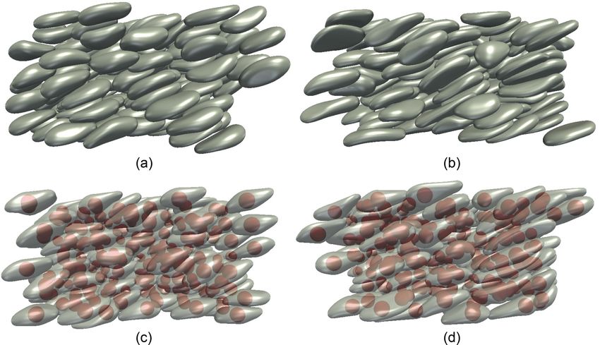
capillary numbers, as well as volume fractions. Figure 3 displays four snapshots of the capsules
in suspensions, once the statistically steady state has been reached, for the most deformable case,
Ca = 0.5, and for different Reynolds numbers. The figure suggests more deformation at higher
Reynolds number; moreover, the nucleated capsules exhibit overall lower deformations: they are
thicker in the regions close to their nucleus while their membrane deformation is larger in the regions
far from the nucleus, which is consistent with the results in Refs. [18–20] on the dynamics of single
nucleated cells. It can be observed that at Re = 0.1, i.e., negligible inertia, most capsules have
their major axis in the shear plane, whereas at Re = 5 there are several capsules with their major
axis oriented in the spanwise direction. To quantify these observations and their role for the global
FIG. 3. Visualization of capsules with Ca = 0.5 and volume fraction φ = 0.31 in the flowing suspension
at statistically steady state for the cases (a) Re = 0.1 without a nucleus, (b) Re = 5 without a nucleus,
(c) Re = 0.1 with a nucleus, and (d) Re = 5 with a nucleus.
044301-10NUMERICAL STUDY OF SUSPENSIONS OF NUCLEATED …
3 3
(a) (b)
2.6 2.6
η 2.2 η 2.2 ∝ Ca−0.153
1.8 1.8
∝ Ca−0.172
1.4 1.4
0.1 0.3 0.5 0.05 0.1 0.15 0.2 0.25 0.3 0.35 0.4 0.45 0.5
Ca Ca
FIG. 4. (a) Relative viscosity of capsule suspensions as a function of the capillary number Ca and the
Reynolds number Re for volume fraction φ = 0.31. Solid lines correspond to capsules without a nucleus, and
the dashed line represents capsules with a rigid nucleus. Gray, orange, and blue pertain to cases with Re = 0.1,
1, and 5. (b) Relative viscosity of the capsule suspensions at Re = 1 with additional simulation points at
different Ca. Blue and black represent capsules with and without nucleus, respectively, and the corresponding
solid line is a power-law fit to the data.
suspension behavior, the eight observables introduced in the previous section will be compared,
namely the relative shear viscosity, the first normal stress difference, the orientation angle, the elastic
energy, the Taylor parameter, the area ratio, the spanwise orientation, and moments of inertia. All
the mean quantities are averaged over time and over capsules/particles.
A. Effects of Reynolds number and capillary number at a fixed volume fraction
We present in Fig. 4 the effect of the capillary number and the Reynolds number on the relative
viscosity of simple and nucleated capsule suspensions. The results in Fig. 4(a) show that the relative
viscosity decreases with the capillary number for both types of capsules; this shear thinning with
deformability is in agreement with previous results for a capsule at negligible inertia and deformable
hyperelastic particles [2,11,14,15], as well as suspensions of flexible filaments [40,41]. The origin
of this behavior will be further examined later when presenting the suspension stress budget.
To better quantify the observed shear thinning, we performed additional simulations with differ-
ent capillary numbers at Re = 1; this is chosen as a compromise so that inertial effects are still
limited, and computational time affordable. The results are presented in Fig. 4(b) with a fitted
power-law curve to the data. The figure shows that the power-law behavior still holds in the presence
of a nucleus inside the capsules. The variations with Ca decrease when increasing the capillary
number, and the relative viscosity tends to approach a constant value, similarly to the limit at large
shear rates of the viscosity curve of power-law fluids obeying a Carreau model.
As concerns the role of inertia, the data in Fig. 4(a) show that the relative viscosity increases with
the Reynolds number, which we explain with a larger drag force on the capsules. The increase is
more pronounced from Re = 1 to 5. In the presence of a nucleus inside the capsule, an additional
effect comes into play, namely the stresses induced by the nucleus. Figure 4 shows that at lower
inertia, Re 1, the presence of the nucleus increases the relative viscosity, which is shown more
clearly in Fig. 4(b). At Re = 5, however, the difference between the cases with and without a nucleus
is very small. This is because at higher inertia, the nucleus highly reduces the capsule deformation
(as shown later in Fig. 7), which tends to reduce the relative viscosity [2], balancing the extra stress
due to the nucleus itself.
To better understand the capsule deformation and to provide an indication of the distribution
variance within the suspensions, we present in Fig. 5 the probability distribution function (PDF)
of the equivalent ellipsoid semiaxes divided by their minimum value, a j /amin , obtained once the
suspension flow has reached the statistically steady state. The largest of two ratios can be seen as
044301-11ALIZAD BANAEI, SHAHMARDI, AND BRANDT
(a) 6 (b) 2.5
5
2
4
1.5
3
1
2
0.5
1
0 0
1 1.5 2 2.5 3 3.5 4 4.5 5 1 2 3 4 5 6 7
a/amin a/amin
FIG. 5. PDF of the two largest values of the equivalent ellipsoid semiaxes divided by their minimum value
for (a) Re = 0.1 and different capillary numbers; (b) Ca = 0.5 and different Reynolds numbers. The vertical
lines represent the mean values.
an indication of the elongation of the capsule, whereas the smallest one provides information about
the shape, being 1 for a prolate spheroid and equal to the largest for an oblate.
When varying the capillary number at negligible inertia, Re = 0.1, panel (a) in the figure, we
observe larger ratios at higher capillary numbers, indicating an average larger deformation of the
capsules. Moreover, at Ca = 0.1 the distribution of the capsule semiaxes has a more distinct peak,
revealing a relatively more uniform distribution of the capsule shape. For this value of the capillary
number, the smallest semiaxes ratio is not far from 1, whereas the largest lies in the range 1
a/amin 2.5, meaning that the equivalent ellipsoids have a prolate shape, with a non-negligible
deformation. At Ca = 0.5, the range of the semiaxes ratio covered by the capsule in suspensions is
much wider and reaches higher values, up to 4.5, suggesting a significant elongation; moreover, the
distance between the two ratios increases, showing that the capsules deform more in one direction;
however, the smaller of the two ratios also increases slightly, so that their cross-sectional area is
elliptical in shape, indicating more heterogeneous stretching of the capsules. In the presence of the
rigid nucleus, we note a lower average deformation at Ca = 0.1. As mentioned above, this is due
to the presence of the nucleus, which makes the middle part of the capsule thicker, which appears
as a reduction in the capsule deformation. At Ca = 0.5, the difference with the simple capsule data
becomes larger for the largest ratio, indicating that the effect of the nucleus is more pronounced at
higher capillary numbers. This will be discussed further in Fig. 7 when presenting average values
from all cases considered.
The role of the Reynolds number on the deformation is reported in Fig. 5(b), which depicts the
PDF of the semiaxes ratios at Ca = 0.5 for Reynolds numbers Re = 0.1 and 5. The relatively peaky
distribution at negligible inertia, indicating capsules of similar shapes, is lost when increasing the
Reynolds number. In this case, we observe a wider distribution of the semiaxes ratios, indicating
a more heterogeneous distribution, as well as larger values (up to values of about 6), revealing the
presence of highly elongated capsules. To quantify the homogeneity of the capsule deformation
and the distribution of the elongation, Fig. 6 displays the root mean square (rms) of the largest
semiaxis ratios of the equivalent ellipsoid. The figure shows that the rms value increases with the
capillary number and, more importantly, with the Reynolds number. This is in agreement with the
visualization of Fig. 3 showing a more heterogeneous distribution in the capsule shape at Re = 5.
Finally, it can be inferred from Fig. 6 that the elongation distribution is more uniform for the capsules
with a nucleus, which can be a result of the lower freedom of the nucleated capsules for deformation,
in particular in their middle part.
044301-12NUMERICAL STUDY OF SUSPENSIONS OF NUCLEATED …
1
0.9
0.8
0.7
a 0.6
amin R.M.S.
0.5
0.4
0.3
0.2
0.1
0.1 0.15 0.2 0.25 0.3 0.35 0.4 0.45 0.5
Ca
FIG. 6. Maximum root-mean-square values of the largest ratio between semiaxes of the equivalent ellipsoid
for different capillary and Reynolds numbers. Solid lines correspond to capsules without a nucleus, and dashed
lines represent capsules with a rigid nucleus. Gray, orange, and blue pertain to cases with Re = 0.1, 1, and 5.
Further examining the capsule deformation, we present in Fig. 7 the average Taylor parameter
and area ratio AR, where the denote the average over time and the capsules. Figures 7(a) and
7(c) clearly show increasing of the capsule deformation with increasing capillary number, which
we attribute to larger viscous than elastic forces. The figure also clearly shows that the capsule
membrane deforms less in the cases with a nucleus, which we relate to the increase in the capsule
thickness in the vicinity of the nucleus [20]. The difference in deformation between capsules with
and without a nucleus, as measured by the mean Taylor parameter and the area ratio, increases
with the capillary number, confirming that the effect of the nucleus is more pronounced for more
deformable membranes. With regard to the effect of inertia, we observe small changes in the Taylor
parameter and the area ratio when increasing the Reynolds number from Re = 0.1 to 1, and more
significant variations at Re = 5 due to the larger drag force on the capsules. Also, the effect of
inertia increases with the capillary number, see especially the Taylor parameter, since inertia can
increase more easily capsule elongation at larger Ca. The changes of the mean Taylor parameter
and area ratio with Ca at fixed Reynolds number, Re = 1, are displayed in Figs. 7(b) and 7(d).
The presence of additional simulation points in these figures shows more clearly the increase of
the capsule deformation with the capillary number as well as the larger difference in deformation of
the simple and nucleated capsules when decreasing the membrane shear modulus, i.e., larger Ca.
As mentioned earlier, we define the orientation of the capsules using the eigenvector of the mo-
ment of inertia tensor corresponding to the minimum eigenvalue, i.e., the direction with maximum
capsule elongation. The orientation with respect to the flow direction is found by projecting this
eigenvector onto the shear plane and computing the angle formed with the streamwise axis. Note
that this is a useful measure if the x-component of the unit vector d is larger than the z-component,
which is the case for many of the configurations investigated here, as shown later. As discussed
in [2,16], the orientation with the flow direction has a clear role in determining the suspension
rheological properties at negligible inertia, i.e., for the capsule suspensions without a nucleus, the
relative viscosity increases with the mean orientation angle in the shear plane.
The PDF of the capsule orientation angle is depicted in Fig. 8 for different capillary and
Reynolds numbers. According to panel (a), at negligible inertia the orientation angle decreases
044301-13ALIZAD BANAEI, SHAHMARDI, AND BRANDT
(a) 0.6 (b) 0.6
0.5
0.4
D 0.4 D
0.3
0.2
0.2 0.1
0.1 0.3 0.5 0.05 0.1 0.15 0.2 0.25 0.3 0.35 0.4 0.45 0.5
Ca Ca
1.25
(c) (d)
1.3
1.2
1.15
AR AR
1.1
1.1
1.05
0.9 1
0.1 0.3 0.5 0.05 0.1 0.15 0.2 0.25 0.3 0.35 0.4 0.45 0.5
Ca Ca
FIG. 7. (a) Mean Taylor parameter and (c) mean area ratio as a function of Re and Ca for volume fraction
φ = 0.31. Solid lines correspond to capsules without a nucleus, and dashed lines indicate the results for
capsules with a nucleus. Gray, orange, and blue denote Re = 0.1, 1, and 5, respectively. (b) Mean Taylor
parameter and (d) mean area ratio at Re = 1 with more simulation points for different Ca.
when increasing the capillary number: at higher capillary numbers, the shear forces, which tend
to align the capsules with the flow direction, are larger than the elastic restoring forces. Panel (b)
of the same figure displays an increase toward large values of the angle as the Reynolds number is
increased from 0.1 to 5. This suggests that the alignment is partially lost when increasing the flow
inertia, and it reflects the fact that some elongated capsules tend to orient in the spanwise direction,
0.07 0.07
(a) (b)
0.06 0.06
0.05 0.05
0.04 0.04
0.03 0.03
0.02 0.02
0.01 0.01
0 0
0 10 20 30 40 50 60 0 10 20 30 40 50
θ(deg) θ(deg)
FIG. 8. PDF of the capsule orientation with respect to the streamwise direction for (a) Re = 0.1 and
different capillary numbers; (b) Ca = 0.5 and different Reynolds numbers. See the main text for the exact
definition of the orientation angle. The vertical lines represent the mean values.
044301-14NUMERICAL STUDY OF SUSPENSIONS OF NUCLEATED …
4.5 4.5
(a) (b)
4 4
3.5 3.5
3 3
2.5 2.5
2 2
1.5 1.5
1 1
0.5 0.5
0 0
0 0.1 0.2 0.3 0.4 0.5 0.6 0 0.1 0.2 0.3 0.4 0.5 0.6
d3 d3
FIG. 9. PDF of the spanwise component of the direction vector, d3 , for (a) Re = 0.1 and different capillary
numbers, and (b) Ca = 0.5 and different Reynolds numbers. The vertical lines represent the mean values.
as discussed next. Finally, it can be seen that the presence of the nucleus does not have a significant
effect on the orientation distributions.
We next study the spanwise orientation of the capsules, quantified by the spanwise component,
d3 , of the unit vector d parallel to the smallest eigenvalue of the moment of inertia tensor. The PDF
of this scalar quantity is displayed in Fig. 9: panel (a) shows that capsules tend to stay longer in
the shear plane for higher capillary numbers, i.e., larger spanwise orientations at lower Ca. Panel
(b) of the same Fig. 9, instead, shows that the spanwise orientation increases with the Reynolds
number so that it is possible to find elongated capsules aligned with the vorticity direction in this
case. Moreover, the distribution is wider for Re = 5.
The average values of the two orientations are presented in Figs. 10(a)–10(d) for all cases
investigated. The data in the figure confirm the trend deduced by the PDF just discussed. We note
in addition that the effect of the rigid nucleus on the shear plane orientation is more pronounced at
Ca = 0.1 while smaller differences are observed when the capsules deform more easily. The addi-
tional analysis performed at Re = 1, see Figs. 10(b) and 10(d), shows more clearly the alignment
with the streamwise direction when increasing the capillary number.
To explain the suspension global behavior, we next consider the different contributions to the
average total stress, as introduced in Sec. III B. This budget is presented in Fig. 11, where the
stresses are made nondimensional by the reference viscous stress (μγ̇ ). The viscous stress is always
about unity, and the changes in the relative viscosity arise from the membrane and rigid particle
(nucleus) stresses. The membrane stress decreases with capillary number; more deformable particles
have lower elastic stresses, reflecting the shear thinning with deformability of the suspensions.
Comparing the cases with and without a nucleus at Re = 0.1 shows that the average elastic stresses
are higher for the capsules without a nucleus, which are associated with higher deformations
(see Fig. 7). Moreover, the elastic stresses increase when increasing the Reynolds number from
0.1 to 5, causing the higher shear viscosity discussed above (see Fig. 4). The stresses from the
nucleus increase with the membrane capillary number from Ca = 0.1 to 0.3; this can be related
to a decreasing distance between nucleus and membrane when increasing deformability, which
increases the viscous shear stress on the rigid nucleus and thus its rotation rate. Further increasing
from Ca = 0.3 to 0.5 does not change significantly the contribution of the nucleus since there is no
further significative change in the shape and size of the gap between the capsule and its nucleus. At a
fixed capillary number, the nucleus stresses increase with the Reynolds number, which we associate
with stronger forces on a sphere at higher Reynolds numbers; however, this increase is not as large
as the increase in the elastic forces.
044301-15ALIZAD BANAEI, SHAHMARDI, AND BRANDT
38 38
(a) (b)
34 34
30 30
θ θ
26 26
(deg) (deg)
22 22
18 18
0.1 0.3 0.5 0.05 0.1 0.15 0.2 0.25 0.3 0.35 0.4 0.45 0.5
Ca Ca
0.2 0.19
(c) (d)
0.18
0.17
0.16
d3 d3
0.14
0.15
0.12
0.1 0.13
0.1 0.3 0.5 0.05 0.1 0.15 0.2 0.25 0.3 0.35 0.4 0.45 0.5
Ca Ca
FIG. 10. (a) Mean capsule orientation with respect to the flow direction and (c) mean spanwise component
of the principal direction of the momentum of inertia tensor associated with the minimum eigenvalue (direction
of maximum elongation) as a function of the Reynolds number Re and capillary number Ca for volume
fraction φ = 0.31. Solid lines correspond to capsules without a nucleus, and dashed lines indicate the results
for capsules with nucleus. Gray, orange, and blue denote Re = 0.1, 1, and 5, respectively. (b) Mean capsule
orientation and (d) mean spanwise component of the direction of maximum elongation at Re = 1 for several
values of Ca.
3
2
1
0
Re = 0.1 Re = 0.1 Re = 5
with nucleus without nucleus with nucleus
FIG. 11. Budget of stress for the nucleated-capsule suspensions with different Reynolds and capillary
number and volume fraction φ = 0.31. Blue denotes the fluid flow contribution, red represents the contribution
of the elastic forces, and orange denotes the contribution of the rigid nucleus to the total shear stress.
044301-16NUMERICAL STUDY OF SUSPENSIONS OF NUCLEATED …
25 35
(a) (b)
30
20
25
W̃sN H W̃sN H
20
15
15
10 10
0.1 0.3 0.5 0.05 0.1 0.15 0.2 0.25 0.3 0.35 0.4 0.45 0.5
Ca Ca
FIG. 12. (a) Mean capsule elastic energy as a function of the Reynolds number, Re, and capillary number,
Ca, for volume fraction φ = 0.31. Solid lines correspond to capsules without a nucleus, and dashed lines
to capsules with a nucleus. Gray, orange, and blue denote different Reynolds numbers, Re = 0.1, 1, and 5.
(b) Mean capsule elastic energy at Re = 1 over a wider range of Ca.
Next, we examine the mean elastic energy of the suspension, normalized with the viscous scale,
defined as the average over all capsules of
1 1 2B 2
W̃sNH = I1 − 1 + + H , (33)
2 Ca I2 + 1 Ca
where H is the mean local curvature, and the invariants I1 and I2 have been defined above. The
results are presented in Fig. 12. The data in the plot indicate that, for a fixed capillary number, the
mean elastic energy increases when increasing the Reynolds number, i.e., increasing inertial effects,
due to the larger deformations of the capsule membrane. The largest bending energy is attained
for the case of simple capsules with the highest Reynolds and capillary numbers considered in this
study. Examining the data at a fixed Reynolds number, we observe a nonmonotonic dependence of
the elastic energy on the capillary number, with a minimum at intermediate values of Ca, followed
by a plateau or a weak increase when inertia is relevant. This minimum appears to move toward
larger values of Ca when decreasing the Reynolds number. The elastic energy is proportional to the
inverse of the capillary number and to the deformation of the membrane, which increases with the
Ca. This combined effect results in a nonmonotonic behavior as shown more clearly in Fig. 12(b)
for Re = 1, where we display data over a wider range of capillary numbers. Finally, we note that
the elastic energy is always less for nucleated capsules than for the simple ones, which we explain
with their smaller deformation.
To quantify the viscoelasticity of the suspensions, we last examine the first normal stress differ-
ence, introduced above in Eq. (26). Figure 13 depicts the average first normal stress as a function of
the capillary number for simple and nucleated capsules and the different Reynolds numbers under
investigation. At a fixed Reynolds number, we mainly observe an increase of the first normal stress
difference with the capillary number due to larger deformation and more alignment in the shear
plane (see Figs. 7 and 10), which results in larger anisotropy of the stress tensor [2]. For capsules
without nucleus, the normal stress difference slightly reduces from Ca = 0.3 to 0.5 at Re = 0.1,
which is consistent with the reduction of mean elastic energy reported in Fig. 12. This may likely
be attributed to a sharper increase in the average wall-normal stress due to the capsule-capsule
interactions. The inertial effects (varying Reynolds number) are highly dependent on the capillary
number since N1 depends both on streamwise and wall normal stresses, which depend differently
on the deformed capsule shape. In general, the nucleated capsule suspensions have a lower first
normal stress difference than simple capsule suspensions due to lower capsule deformation, as is
clearly shown in Fig. 13(b) at Re = 1. As a consequence of the presence of a nucleus, N1 is less
sensitive to the Reynolds number in nucleated suspensions. In fact, the first normal stress difference
044301-17ALIZAD BANAEI, SHAHMARDI, AND BRANDT
2.5 2
(a) (b)
1.8
1.6
N1 1.5 N1 1.4
1.2
1
0.5 0.8
0.1 0.3 0.5 0.05 0.1 0.15 0.2 0.25 0.3 0.35 0.4 0.45 0.5
Ca Ca
FIG. 13. (a) First normal stress difference as a function of Re and Ca for volume fraction φ = 0.31. Solid
lines correspond to capsule without a nucleus, whereas dashed lines represent results for capsules with a
nucleus. Gray, orange, and blue denote Re = 0.1, 1, and 5. (b) First normal stress difference over a wider
range of Ca for Re = 1.
is a result of the capsule anisotropy in the shear plane, and the presence of a rigid nucleus reduces
this anisotropy.
B. Effect of volume fraction
In this section, we study the effect of the capsule volume fraction on the rheological properties
of the suspensions and the capsule average motion and deformation. We consider two capillary
numbers, Ca = 0.1 and 0.3, and two Reynolds numbers, Re = 1 and 5. The relative suspension
viscosity is depicted in Fig. 14, whereas the average capsule properties—the Taylor parameter, the
area ratio, the angle between the axis of largest elongation and the streamwise direction, and the
spanwise component of the unit vector parallel to this axis orientation—are presented in Fig. 15.
As expected, the relative viscosity increases with the volume fraction, due to the increased forces
from the suspended objects back to the flow. The rate of increase of the relative viscosity is higher
for Ca = 0.1, in agreement with the observations of Matsunaga et al. [2]. The difference between the
relative viscosity of the sample and the nucleated capsule suspensions is secondary in comparison
to the effect of volume fraction, similar to the case of deformable objects when variations of the
capillary number are less relevant than variations of the volume fraction [14,15,41]; in this particular
2.6
2.4
2.2
η 2
1.8
1.6
1.4
1.2
0.1 0.2 0.3
Ca
FIG. 14. Relative viscosity of nucleated and denucleated capsules vs the volume fraction φ. Solid and
dashed lines represent capsules with and without a nucleus, whereas gray and orange indicate flows with
Re = 1 and 5 at Ca = 0.3; the purple lines show the results for Re = 1 and Ca = 0.1.
044301-18NUMERICAL STUDY OF SUSPENSIONS OF NUCLEATED …
(a) 1.25 (b) 0.55
0.5
1.2
0.45
1.15 0.4
D AR 0.35
1.1 0.3
0.25
1.05
0.2
1 0.15
0.1 0.2 0.3 0.1 0.2 0.3
φ φ
0.22 0.2
(c) (d)
0.18
0.2 0.16
θ d3 0.14
0.12
0.18
0.1
0.08
0.16
10 20 30 0.06
0.1 0.2 0.3
φ φ
FIG. 15. Averaged capsule deformation measured in terms of (a) the Taylor parameter and (b) area ratio.
Particle orientation measured by (c) the average angle between the projection in the shear plane of the axis of
the largest capsule elongation and the streamwise direction for Ca = 0.3, and (d) average spanwise component
of the unit vector parallel to the axis of maximum elongation. Solid and dashed lines represent capsules with
and without a nucleus, whereas gray and orange indicate flows with Re = 1 and 5 and Ca = 0.3. The purple
lines show the results for Re = 1 and Ca = 0.1.
case, this can be the result of different effects having the opposite impact on the relative viscosity: the
capsule deformation, orientation angle, and the presence of the rigid nucleus. The relative viscosity
increases with the mean capsule deformation and the orientation angle (lower alignment with the
flow direction) [2]; in addition, the stresses due the nucleus tend to increase the relative viscosity.
For a fixed capillary and Reynolds number, when adding a nucleus, these three effects can balance
each other as particle deformation is reduced [see Figs. 15(a)–15(c)], resulting in small variations
of the effective viscosity, as shown in Fig. 14.
Figures 15(a) and 15(b) show that the capsule deformation mainly increases with the volume
fraction due to the larger shear between the capsules. There is a slight reduction in the area ratio
with the volume fraction at Ca = 0.3 and Re = 1 which can be attributed to the larger normal
forces on the capsule membrane from the adjacent capsules. The angle between the projection in
the shear plane of the axis of largest capsule elongation and the streamwise direction is displayed in
Fig. 15(c), revealing a reduction in the orientation angle, i.e., a stronger average alignment, with the
volume fraction due to larger shear forces between the capsules. The spanwise component of the
capsule orientation, depicted in Fig. 15(d), displays an increase with the volume fraction and a more
disordered microstructure (yet with the axis of elongation almost orthogonal to the wall-normal
direction, due to increased capsule-capsule interactions).
Figure 16, left panel, represents the first normal stress difference as a function of the volume
fraction, indicating an increase in viscoelasticity with the volume fraction. The increase is due to
increasing elastic forces as well as a decrease of the mean orientation angle with the volume fraction
(see Fig. 15), which adds more anisotropy to the flow; see also Ref. [2]. The data in the figure also
show that, at constant Reynolds number, the first normal stress difference is lower for the nucleated
044301-19ALIZAD BANAEI, SHAHMARDI, AND BRANDT
(a) 2 (b) 2
1.6 1.6
1.2 1.2
N1 W̃sN H
0.8 0.8
0.4 0.4
0 0
0.1 0.2 0.3 0.1 0.2 0.3
φ φ
FIG. 16. (a) First normal stress difference and (b) elastic energy vs the capsule volume fraction. Solid
and dashed lines represent capsules with and without a nucleus, whereas gray and orange indicate flows with
Re = 1 and 5 with Ca = 0.3. The purple lines show the results for Re = 1 and Ca = 0.1.
capsules than for the simple capsules due to the lower deformation in the presence of a nucleus.
Finally, it can be observed that the effect of the presence of a nucleus on the first normal stress
difference is more pronounced than on the relative viscosity. Finally, the mean elastic energy of the
capsules is shown in Fig. 16(b) versus the volume fraction. Here, we can see that the mean capsule
elastic energy increases with the volume fraction and the Reynolds number, due to the increased
deformation of the capsules, in agreement with the results in Fig. 15. The increased deformation is
the result of stronger capsule-capsule interactions at higher volume fractions. Examining the data
at constant Reynolds number, we note that the elastic energy is lower for the nucleated capsule
suspensions, which reflects the lower deformation of the capsule membranes in the presence of a
rigid nucleus.
V. CONCLUSIONS
We present the results of interface-resolved numerical simulations of suspensions of initially
spherical capsules with and without a rigid nucleus inside. The capsule is modeled as a thin
hyperelastic membrane enclosing a droplet of a second fluid, which is assumed here to have the
same density and viscosity as the outer ambient fluid. Continuum elasticity equations are solved
for the membrane assuming a Neo-Hookean material with the fluid and solid motions coupled
via an immersed boundary method. To model the presence of a nucleus, we add a rigid particle
with radius equal to half the initial radius of the capsule and located initially at the center of each
capsule. A series of simulations is performed to study the effect of capillary number, i.e., membrane
deformability, Reynolds number, i.e., inertial effects, and volume fraction on the global suspension
behavior for capsules with and without a nucleus. In particular, we report the relative viscosity
and the first normal stress difference of the different suspensions considered, and we try to relate
the macroscopic system behavior to the capsule deformation, orientation in the shear plane, degree
of alignment in the spanwise direction, and elastic energy. The stress budget for suspensions of
different capillary and Reynolds numbers is also presented.
The results indicate that, at a constant Reynolds number, the relative viscosity of the suspensions
decreases with the capillary number, so the suspension is shear thinning with respect to deforma-
bility, as observed in previous studies on suspensions of flexible and deformable objects. For the
range of parameters investigated, the effect of the flow inertia becomes evident when increasing
the Reynolds number from 1 to 5, leading to an increase of the relative viscosity. Inertial effects
are minimal for Re ∈ [0.1, 1]. The capsule deformation increases with inertia and decreases in the
presence of a rigid nucleus; in particular, the presence of the nucleus reduces the capsule mean
deformation in all cases considered. The alignment with the flow is found to depend mainly on the
capillary number and to increase with the Reynolds number. The presence of the nucleus is more
044301-20You can also read


