PHYSICAL REVIEW ACCELERATORS AND BEAMS 24, 031601 (2021)
←
→
Page content transcription
If your browser does not render page correctly, please read the page content below
PHYSICAL REVIEW ACCELERATORS AND BEAMS 24, 031601 (2021)

                          Mathieu unit cell as a template for low emittance lattices
                                                            B. Riemann
                                      Paul Scherrer Institut, CH-5232 Villigen PSI, Switzerland

                          (Received 12 February 2020; accepted 25 February 2021; published 24 March 2021)

                 The multibend achromat (MBA), which often serves as a building block for modern low-emittance
              storage rings, is composed of a repetition of unit cells with optimized optical functions for low emittance in
              the achromat center, as well as end cells for dispersion and optics matching to insertion devices. In this
              work, we describe the simplest stable class of unit cells that are based on a longitudinal Fourier expansion,
              transforming Hill equations to Mathieu equations. The resulting cell class exhibits continuously changing
              dipolar and quadrupolar moments along the beam path. Although this elementary model is defined by only
              three parameters, it captures a significant amount of notions that are applied in the design of MBAs. This is
              especially interesting as Mathieu cells can be viewed as an elementary extension of Christofilos’ original
              model of alternating-gradient focusing, while their sinusoidal bending and focusing functions lend
              themselves to future applications in undulatorlike structures. Mathieu cells can be used to estimate the
              range of reasonable cell tunes and put an emphasis on the combination of longitudinal gradient bending and
              reverse bending, as well as on strong horizontal focusing to reach emittances lower than the classic
              theoretical minimum emittance cell. Furthermore, the lowest emittances in this model are accompanied by
              small absolute momentum compaction factors.

              DOI: 10.1103/PhysRevAccelBeams.24.031601

                    I. INTRODUCTION                                    can be selected in an arbitrary manner. E.g., in [13] steplike
                                                                       basis functions are used and truncated at a high order, and a
   For practical reasons, the evolution of lattices for
                                                                       particle-swarm based optimization is applied in the result-
low-emittance synchrotron storage rings, including the
                                                                       ing high-dimensional parameter space.
double-bend [1], triple-bend [2], and quadruple-bend
                                                                          The choice of sinusoidal basis functions is motivated in
achromats [3], is mostly based on modeling them with
                                                                       Sec. II—in essence, higher harmonics of the unit cell
discrete elements representing accelerator magnets. This
                                                                       require stronger magnet pole-tip fields than lower harmon-
also includes computations for the emittance minimum of a
                                                                       ics, which is especially important for miniaturized magnet
given periodic cell [4,5].
                                                                       arrangements, where the lowest harmonics will dominate.
   Recent developments in the field of multibend achromats
                                                                       This statement can be related to the common treatment of
(MBAs) have shown that longitudinal gradients in magnet
                                                                       undulators, which usually starts with a description of the
strength can significantly decrease emittance (e.g., [6–8]),
                                                                       lowest harmonics (e.g., [14]).
and that reverse bends [9] (see also Veksler’s suggestion in
                                                                          The focusing functions for Mathieu cells, which we
[10]) are necessary to fully exploit these longitudinal
                                                                       introduce in this work, contain the lowest possible order of
gradients [11,12]. It has also been known for a long time
                                                                       such basis functions that yield stable solutions and are
that combined-function magnets can help to decrease
                                                                       discussed in Sec. III. It is interesting to note that these
horizontal emittance by manipulating damping partitions
                                                                       sinusoidal focusing forces are also the starting point for
(see e.g., [2,3]).
                                                                       Christofilos’ description of alternating-gradient focusing
   These facts can inspire to model the focusing and
                                                                       [15]. However, his derivations focus on qualitative aspects
bending functions of the periodic lattice structure (i.e.,
                                                                       of the motion, and not on solving the underlying differ-
the unit cell) directly, by a set of basis functions that are
                                                                       ential equations—these are Mathieu equations.
periodic in cell length, instead of using distinct elements to
                                                                          Afterwards, bending functions are included in Sec. IV.
represent magnets. In principle, the type of basis function
                                                                       The resulting parameter space is three-dimensional and can
                                                                       be explored without difficulty. For the resulting cells,
                                                                       synchrotron integrals, emittance and momentum compac-
Published by the American Physical Society under the terms of          tion can be computed, and example solutions are studied.
the Creative Commons Attribution 4.0 International license.
Further distribution of this work must maintain attribution to            The scaling laws for unit cells are investigated in Sec. V
the author(s) and the published article’s title, journal citation,     with an emphasis on the “chromaticity wall” and selecting
and DOI.                                                               the optimal cell length. A new objective function for the

2469-9888=21=24(3)=031601(15)                                  031601-1               Published by the American Physical Society
B. RIEMANN PHYS. REV. ACCEL. BEAMS 24, 031601 (2021)
emittance of an arc with optimally scaled cell length is d2
xðsÞ þ κðsÞxðsÞ ¼ 0;
obtained, including constraints on applicable sextupole ds2
field strength. After further approximating the applicable d2
pole-tip fields of magnets for a specific example tune, an yðsÞ − κðsÞyðsÞ ¼ 0: ð4Þ
example cell is constructed using parameters of the SLS 2.0 ds2
storage ring in Sec. VI. Note that bending magnets (Sec. IV), chromatic effects
(Sec. III A, Sec. V) and fringe effects (Sec. V C) are
II. LONGITUDINAL HARMONICS discussed in later sections.
Assuming κðsÞ to be constructed of basis functions
Consider the magnetic field on a cylinder with radius r,
cosðk̄p sÞ, the most elementary case to consider is P ¼ 0
and the beam path leading through its axis. For simplicity,
because then κ ¼ const. As the sign of κ is different for the
we neglect the curvature of the path, although the argument
horizontal and vertical plane, bounded motion can only be
naturally extends to that case. In a current-free region, a
achieved in one of them, and stable particle motion is
scalar potential defining the magnetic field B ⃗ ¼ −∇Ψ
2
impossible.
obeys the Laplace equation ∇ Ψ ¼ 0 [16]. In the afore- On the other hand, as we will see, the case P ¼ 1 already
mentioned periodic cell, this potential can be expressed as allows for stable motion. The resulting parameter space is
linear combination of basis functions low-dimensional, and thus lends itself to plain exploration.
We first investigate such a model without bending and thus
Ψ̃n;p ¼ Djnj ðk̄p ; rÞeinϕ eik̄p z ð1Þ without dispersion. An additional parameter for bending is
then included, and synchrotron radiation integrals (includ-
for integers p and n, and with the definition of ing damping partition, emittance, momentum compaction)
are computable.
Dn ðk̄p ; rÞ ¼ 2n I n ðk̄p rÞ=k̄np ; ð2Þ
III. MATHIEU EQUATIONS IN 2D
where I n is the modified Bessel function of the first kind To simplify the following calculations, we consider a
and order n (see the Appendix A). Defining the period of normalized cell with the dimensionless length π. The
the cell to be L, one obtains k̄p ¼ 2πp=L. normalized longitudinal cell coordinate u is linked to the
When selecting a longitudinal harmonic with positive n, standard cell coordinate via s ¼ Lu=π (see Appendix B).
the radial field component at radius r is given as Still considering the aforementioned focusing function
(Appendix A) for the case P ¼ 1, we obtain
d2
dDn nþ2 xðuÞ þ kðuÞxðuÞ ¼ 0;
Br ∝ ∝ rn−1 1 þ k̄2p r2 þ : ð3Þ du2
dr 4nðn þ 1Þ
d2
yðuÞ − kðuÞyðuÞ ¼ 0 ð5Þ
For p ¼ 0 this reduces to the commonly known behavior du2
Br ∝ rn−1 . The higher the longitudinal harmonic jpj and
with a cell-normalized focusing strength
thus the value of k̄p , the larger the term in square brackets,
and the more difficult an application of the desired on-axis
kðuÞ ¼ k0 − 2k1 cosð2uÞ; ð6Þ
multipolar fields will become.
Therefore, lower longitudinal harmonics of multipolar
where the factor −2 was selected arbitrarily for alignment
fields are preferable to higher harmonics. Further assuming
with standard notation. The equations of motion are now
the unit cell to possess symmetry planes, we can select
Mathieu equations, both depending on the same set of
cosine functions cosðk̄p sÞ as basis functions with increas-
parameters k0 , k1 .
ing positive order p ≤ P.
We analyze the horizontal motion based on Floquet
solutions, mainly following the approach outlined in [19].
A. Biplanar stability These can be written in the normal form [20]
The next task is finding the lowest maximum order P for
which stable particle motion could be achieved. The XðuÞ ¼ ei2νx u fðuÞ; ð7Þ
transverse linear motion of a charged particle with design
energy in a decoupled accelerator lattice without bending where 2νx is the characteristic exponent and νx is the
magnets can be described using Hill differential equations horizontal cell tune, i.e., the betatron phase advance in a
[17,18] cell divided by 2π. We express the π-periodic function
031601-2MATHIEU UNIT CELL AS A TEMPLATE FOR LOW … PHYS. REV. ACCEL. BEAMS 24, 031601 (2021)
X
Q
fðuÞ ¼ f q ei2qu ð8Þ
q¼−Q
as a truncated Fourier series with the highest harmonic
being Q. For the following calculations, Q ¼ 50 is suffi-
⃗ we
cient. Then using the f q as components of a vector f,
can write Eq. (5) as
⃗
0 ¼ Mðνx Þf; ð9Þ
where Mðνx Þ is a (truncated) tridiagonal matrix of size
ð2Q þ 1Þ × ð2Q þ 1Þ with entries
k1
Mq;q ¼ 1; M q;q−1 ¼ M q;qþ1 ¼ : ð10Þ
4ðq þ νx Þ2 − k0
To solve this system, we require prior knowledge of νx .
This can be achieved using the determinant of Mðνx ¼ 0Þ
and the Whittaker-Hill formula [19,21]
sin2 ðπνx Þ ¼ Cðk0 ; k1 Þ ð11Þ
FIG. 1. Stability diagram in the ðk0 ; k1 Þ plane. Blue-shaded
with the definition regions are stable for horizontal motion, with the blue line
pffiffiffiffiffi indicating νx ¼ 0.5. Green-shaded regions are stable for vertical
Cðk0 ; k1 Þ ¼ det Mðνx ¼ 0Þ · sin2 ðπ k0 =2Þ: ð12Þ motion, with the green line indicating νy ¼ 0.5. The region
overlaps are stability islands.
It is apparent from Eq. (11) that periodic solutions only
exist for
β̃x ðuÞ ¼ XðuÞX ðuÞ=I x ¼ fðuÞf ðuÞ=I x ð14Þ
0 < Cðk0 ; k1 Þ < 1; ð13Þ
with
leading to limited regions in ðk0 ; k1 Þ space where horizon-
tally stable motion occurs. Furthermore, it follows from
I x ¼ ℑfX ðuÞX0 ðuÞg ¼ ℑff ðuÞf 0 ðuÞg; ð15Þ
Eq. (5) that stability of vertical motion is equivalent to that
of horizontal motion when mirroring the ðk0 ; k1 Þ regions at
the origin. The intersection of stability regions for both
planes leads to islands of stability for transverse motion
(see Fig. 1, cf. [[21] Fig. 5]).
The islands differ significantly in the maximal focusing
strength that needs to be applied. The only stable solutions
with reasonable max jkðuÞj ≤ 2 all occur in a single
stability island. This ‘neck-tie’ island, named here in
analogy to the corresponding diagram for the FODO lattice
[22] is shown in Fig. 2 in more detail. We conclude that
reasonable cell designs require ðk0 ; k1 Þ in this island, which
has cell tunes νx ; νy < 1=2.
A. Tune map for chromaticity
As there exists a bijective mapping of stable-motion
quadrupole configurations to tunes ðk0 ; k1 Þ ↔ ðνx ; νy Þ, we
are able to study the properties of Mathieu unit cells
directly in tune space.
Given νx , one may solve Eq. (9) for fðuÞ. Dimensionless FIG. 2. Stability diagram for the neck-tie island. Shading and
optical functions in the unit cell of length π are computed colored lines like in Fig. 1. Gray lines are isolines of νx or νy in
from XðuÞ in Eq. (7) as (see, e.g., [23]) steps of 0.1.
031601-3B. RIEMANN PHYS. REV. ACCEL. BEAMS 24, 031601 (2021)
and they can be used to compute the linear chromaticity The average curvature h1=ρi in a cell is defined by the
with the horizontal and vertical optical functions β̃x ; β̃y by arc geometry of the storage ring and the bending of end-
(cf. [14]) cells. When assuming the curvature to contain low-order
longitudinal harmonics in the same manner as the focusing
Z π
strengths (P ¼ 1), we can parametrize
4πξx ¼ − β̃x ðuÞkðuÞdu;
0
Z π 1=ρðuÞ ¼ h1=ρibðuÞ ð18Þ
4πξy ¼ β̃y ðuÞkðuÞdu: ð16Þ
0 with a cell-normalized dipole strength
Following from the aforementioned symmetry of vertical
bðuÞ ¼ 1 − 2b1 cosð2uÞ: ð19Þ
and horizontal motion in ðk0 ; k1 Þ space, we obtain the
vertical chromaticity for a given tune as
Note that bðuÞ shares the same mirror symmetry around
u ¼ 0 and u ¼ π=2 as kðsÞ, as this is the most elementary
ξy ðνx ; νy Þ ¼ ξx ðνy ; νx Þ: ð17Þ approach.
Also, an upper limit on jbj, and thus jb1 j, exists given
The results of the linear chromaticity computation are by achievable dipole field strength independent of cell
shown in Fig. 3. In the usable regions of the tune map, i.e., length, as
considering stop-bands around the half-integer resonances,
we obtain negative chromaticities ξx;y > −2.5. max jBj
Note that the general dependency of cell tune on particle max jbj ¼ : ð20Þ
Bc
energy—without effects by higher-order multipoles yet to
be introduced—can be obtained by scaling the ðk0 ; k1 Þ Here we introduced the characteristic magnetic field
vector corresponding to a given tune in the neck-tie density
diagram in Fig. 2.
Bc ¼ ðBρÞh1=ρi ð21Þ
IV. BENDING AND EMITTANCE
depending on the beam rigidity ðBρÞ.
The next task is to include bending into the unit cell. We Normalizing with the average curvature, the inhomo-
assume that the curvature is sufficiently small so that we geneous Hill equation for linear dispersion ηðsÞ [14,22] can
can neglect the effect of weak focusing on kðsÞ in Eq. (5). be rewritten as (see Appendix B)
Following the same line of reasoning we also neglect edge
focusing. d2
η̃ðuÞ þ kðuÞ η̃ðuÞ ¼ bðuÞ ð22Þ
du2
with
2
π ηðuÞ
η̃ðuÞ ¼ : ð23Þ
L h1=ρi
We recognize that the solutions η̃ðuÞ of Eq. (22) are
additive in bðuÞ. Let η̃ð0Þ ðuÞ be the solution for bðuÞ ¼ 1
and let η̃ð1Þ ðuÞ be the solution for bðuÞ ¼ −2 cosð2uÞ. Then
the general solution is linear in b1 , as
η̃ðuÞ ¼ η̃ð0Þ ðuÞ þ b1 η̃ð1Þ ðuÞ: ð24Þ
The driving term bðuÞ requires η̃ðuÞ to be periodic in π,
X
Q X
Q
η̃ðuÞ ¼ v0 þ 2 vq cosð2quÞ ¼ vq e2iqu ; ð25Þ
q¼1 q¼−Q
FIG. 3. Tune map for horizontal linear chromaticity. The
borders of the neck-tie island are shown as colored edges of so that Eq. (22) reduces to the solvable linear equation
the plot, corresponding to the lines in Fig. 2. system
031601-4MATHIEU UNIT CELL AS A TEMPLATE FOR LOW … PHYS. REV. ACCEL. BEAMS 24, 031601 (2021)
Mðνx ¼ 0Þ⃗v ¼ c⃗ ð26Þ Jx ¼ 1 −
I4
ð32Þ
I2
with c0 ¼ 1=k0 , c1 ¼ c−1 ¼ b1 =ð4 − k0 Þ and all other
components of c⃗ being zero. The solution η̃ðuÞ can then must fulfill 0 < J x < 3 [24,25].
be constructed using v⃗ . In low-emittance rings, Jx > 1 is favored [26] as the
effects of quantum excitation are then shifted from the
transverse into the longitudinal plane.
A. Synchrotron integrals The dispersion action HðsÞ occurring in the quantum
Having introduced bending and dispersion, knowledge excitation integral
of linear momentum compaction can be obtained, which is Z π
proportional to the synchrotron integral [24,25] for the unit
I5 ¼ HðuÞjbðuÞ3 jdu ð33Þ
cell 0
Z π can be computed using the Floquet solution as
I1 ¼ bðuÞη̃ðuÞdu: ð27Þ
0
HðuÞ ¼ γ̃ η̃2 þ 2α̃ η̃ η̃0 þ β̃η̃02
To gain some insight into the behavior of I 1 , we insert ¼ jX 0 ðuÞη̃ðuÞ − XðuÞη̃0 ðuÞj2 =I x : ð34Þ
Eq. (24) and obtain
Z One can then obtain the emittance ϵ ∝ I 5 =ðI 2 Jx Þ. However,
π
I 1 ðb1 Þ ¼ ð0Þ
η̃ ðuÞdu we are interested in the emittance relative to that of a
0 normalized theoretical minimum emittance (TME) cell [5],
Z Z π
π
pffiffiffiffiffi
þ b1 η̃ð1Þ ðuÞdu − 2 η̃ð0Þ ðuÞ cosð2uÞdu I I5 12 15 I 5
0
Z π
0 Fðνx ; νy ; b1 Þ ¼ 5 ¼ ; ð35Þ
I2Jx I 2 TME π 3 I 2 Jx
− b21 η̃ð1Þ ðuÞ½1 þ cosð4uÞdu: ð28Þ
0 as it is independent of cell length.
By its definition preceding Eq. (24) and due to symmetry
conditions, B. Results
Z We can now search for the optimal b1 parameter to reach
π minimum emittance ratio F for a given tune ðνx ; νy Þ; the
η̃ð1Þ du ¼ 0: ð29Þ
0 results are shown in Fig. 4. Sub-TME emittances are
reached for 0.4 < νx < 0.5, with a minimal F < 0.7. We
Although η̃ðuÞ is the solution of a parametric oscillator, we see that, in this band, increasing νy only has slight effects—
may expect it to mainly oscillate at the driving frequency increasing J x and decreasing F. Damping partitions for the
cosð2uÞ, making the last coefficient in Eq. (28) small. sub-TME region are in a feasible interval Jx ∈ ½1.5; 2.5.
We proceed by computing radiation properties for the The region with small absolute momentum compaction
normalized cell. The synchrotron integrals related to in Fig. 4 has a similar location and shape as that of sub-
radiation loss and damping partitions are [24,25] TME emittance—this is consistent with the general obser-
Z π
vation that low-emittance lattices require small absolute
I2 ¼ bðuÞ2 du ¼ πð1 þ 2b21 Þ ð30Þ momentum compaction.
0 To further investigate the influence of the dipole coef-
ficient b1 , which is not visible in the projections in Fig. 4,
and figures of merit for an example tune νx ¼ 0.45, νy ¼ 0.35
Z π
and a range of b1 are shown in Fig. 5. According to Eq. (28)
I4 ≈ 2 bðuÞkðuÞη̃ðuÞdu: ð31Þ we expect I 1 to be quadratic in b1 , with the quadratic
0 coefficient almost vanishing—we obtain a visibly linear
dependency here. The location of I 1 ¼ 0 and the location of
The expression used for I 4 is an approximation in which, the minimal F again illustrate that low emittances and low
in consistence with our assumption, the contribution of momentum compaction are closely related.
weak focusing has been omitted. In full analogy to I 1 and As the damping partition is in a usable range, the
substituting η̃ð·Þ → kη̃ð·Þ , we find that I 4 ðb1 Þ is also a minimum emittance solution for this tune is feasible.
quadratic function of b1 . The example solution parameters, figures of merit, and
In order for a flat lattice to allow damping in all optical functions are shown in Fig. 6 and Table I. It can be
dimensions, the horizontal damping partition seen that (1) positive bending and defocusing quadrupole
031601-5B. RIEMANN PHYS. REV. ACCEL. BEAMS 24, 031601 (2021)
FIG. 4. From left to right: (1) optimized b1 for minimal TME emittance ratio F for b1 < 1.3, (2) resulting F up to 5, with sub-TME
region in yellow, (3) horizontal damping partition J x , invalid region in gray, (4) momentum compaction integral I 1 up to 1, with the red
area indicating jI 1 j < 0.05.
fields overlap, increasing Jx [3], and that (2) reverse We define a cell-normalized sextupolar field function
bending occurs at the position of maximum dispersion [11].
V. SEXTUPOLES AND CHROMATICITY WALL mðuÞ ¼ m0 þ 2m1 cosð2uÞ; ð38Þ
To control linear chromaticity occurring according to
Eq. (16), the introduction of sextupolar fields
which includes the fundamental harmonic and shares the
1 d2 By same mirror symmetry as bðuÞ and kðuÞ, yielding the most
μðsÞ ¼ ðx ¼ 0; sÞ; ð36Þ elementary mode.
2ðBρÞ dx2
For the unit cell with length π, this results (Appendix B)
is required. Full compensation leads to the condition [22] in an equation system
Z
!
4πξx ¼ − βx ðsÞηx ðsÞμðsÞds;
Z
!
4πξy ¼ βy ðsÞηx ðsÞμðsÞds: ð37Þ
FIG. 5. TME emittance ratio F (blue), horizontal damping
partition J x (green) and momentum compaction integral I 1
(yellow) in dependence of the dipole coefficient b1 . The limits FIG. 6. Top: optical functions for the example solution char-
of J x for stable motion, as well as the b1 value used in the acterized in Table I. Bottom: corresponding distribution of dipole
example solution, are denoted with dashed lines. (black), quadrupole (blue), and sextupole fields (yellow).
031601-6MATHIEU UNIT CELL AS A TEMPLATE FOR LOW … PHYS. REV. ACCEL. BEAMS 24, 031601 (2021)
1 hη̃β̃x i TABLE I. Example multipole parameters of a Mathieu cell and
ξx ¼ − hβ̃x η̃mi ¼ − m0 − hη̃β̃x cosð2uÞim1 ; its figures of merit.
2 2
1 hη̃β̃y i Parameter Value
ξy ¼ hβ̃y η̃mi ¼ m0 þ hη̃β̃y cosð2uÞim1 ; ð39Þ
2 2 Dipole coefficient b1 −1.1100
Quadrupole coefficient k0 0.04801
which can be uniquely solved for m0, m1 ; h·i denotes the k1 0.8554
average of the respective quantity over the cell length. The Sextupole coefficient m0 −0.5550
sextupole coefficients for F–optimized cells with given cell m1 0.5855
tunes are shown in Fig. 7 and also included for the example Horizontal cell tune νx 0.4500
in Table I. Vertical cell tune νy 0.3500
Nat. horizontal cell chromaticity ξx −1.8323
Nat. vertical cell chromaticity ξy −0.6716
A. Sextupole-limited arc emittance
Horizontal damping partition Jx 1.8219
We want to find the cell length yielding the optimal
Radiation integral I1 −0.0191
emittance for a given limited sextupole strength max jmj. In TME ratio F 0.6617
an arc of constant average curvature h1=ρi, the actual Arc emittance factor (sec. V) G 0.9963
sextupole strength μðuÞ scales relative to the sextupole
strength of the normalized cell mðuÞ as (see Appendix B)
4 ϵ ∝ FL3 ∝ G; with G ¼ F ðmax jmjÞ3=4 : ð42Þ
π mðuÞ
μðuÞ ¼ : ð40Þ
L h1=ρi We can use G as an objective function for optimization,
thus including sextupolar fields in a straightforward man-
This disadvantageous dependency on cell length is some- ner, to find an optimal value for b1.
times referred to as “chromaticity wall” [27] and is a major Tune maps for figures of merit in which b1 is selected to
limitation for shrinking unit cells. yield the optimal G are shown in Fig. 8. We can observe
The optimal cell length can be obtained from the above that the characteristics for the emittance ratio F and the
equation as damping partition Jx did not change significantly, although
1=4 the tune-space region of low momentum compaction has
max jmj reduced in size.
L¼π : ð41Þ
max jμjh1=ρi Furthermore, it is interesting that the two regions with
G ≤ 1 exist. One region has a significantly reduced
It is well known (e.g., [28]) that the emittance scales with horizontal focusing νx < 0.2. Unfortunately, the low G
the cube of bending angle per cell, and thus in our case values in this region are mainly influenced by a large and
∝ L3 . Reusing the definition of TME-normalized emittance infeasible damping partition Jx > 3 (see Fig. 9).
F in Eq. (35), we find that the optimal emittance scales as The other region overlaps with the low-emittance regime
shown in Fig. 4, with the difference that there is now a
slight preference for less vertical focusing. The additional
parameters G and max jmj for our example configuration,
which is located in that region (see also Table I and Fig. 5),
are shown in Fig. 10.
B. Extensions to higher harmonics
Having obtained an optimized solution for the Mathieu
cell (P ¼ 1), it is possible to iteratively increase P and re-
optimize the solution locally. However, the number of free
parameters increases significantly. In the scope of this
work, we increase to P ¼ 2 only for the sextupolar field
component, so that
mðuÞ ¼ m0 þ 2m1 cosð2uÞ þ 2m2 cosð4uÞ: ð43Þ
FIG. 7. Values of m0 (left) and m1 (right) for optimized This has the advantage that the dimensions of the free
emittance ratio F at a given cell tune. parameter space ðνx ; νy ; b1 Þ do not increase—the additional
031601-7B. RIEMANN PHYS. REV. ACCEL. BEAMS 24, 031601 (2021)
FIG. 8. From left to right: (1) optimal G objective, (2) emittance ratio F for G objective, (3–4) quantities like in Fig. 4 (see legend
therein) for optimal G.
harmonic coefficient m2 is used to reduce max jmj without
changing optical functions.
To compensate chromaticity, we are required to solve a
more general variant of Eq. (39)
⃗ x · ⃗m ¼ −ξx ;
A ⃗ y · ⃗m ¼ ξy
A ð44Þ
with the components of A ⃗ x;y holding scaled Fourier
components of η̃β̃x;y . This system is underdetermined; its
solution space in three dimensions is given as
⃗ x×A
⃗m ¼ ⃗mð0Þ þ aðA ⃗ y Þ for a ∈ R; ð45Þ
with ⃗mð0Þ being an arbitrary solution. For our computation
FIG. 9. Figures of merit in dependence of the dipole coefficient
b1 (see Fig. 5) for νx ¼ 0.15, νy ¼ 0.35. we use the least-squares solution of the system (44).
The quantity max jmj can be computed with minor effort,
as we require it to be minimal under the constraint of full
chromaticity compensation—this is achieved using an
elementary optimization procedure on the scalar a.
FIG. 10. G objective for the standard sextupole harmonics
(P ¼ 1: yellow) and extended harmonics (P ¼ 2: magenta) as
well as max jmj (P ¼ 1: red, P ¼ 2: dark gray) in dependence of FIG. 11. Distribution of dipole (black), quadrupole (blue) and
the dipole coefficient b1 . The example value of b1 is marked with sextupole fields (yellow) for the example solution marked in
a dashed line. Fig. 10. The optical functions are identical to those in Fig. 6.
031601-8MATHIEU UNIT CELL AS A TEMPLATE FOR LOW … PHYS. REV. ACCEL. BEAMS 24, 031601 (2021)
FIG. 12. Figures of merit for G-optimized solutions with extended sextupole harmonics (P ¼ 2) in tune space. See legend in Fig. 8.
The results of this optimization in tune space are shown By series expansion of By ðx; sÞ in x (Appendix C),
in Fig. 12. Relative to the setup using just constant and the dipolar and quadrupolar fields on the beam path are
fundamental harmonic (P ¼ 1), an overall reduction of the given by
G objective has been achieved, reaching values G < 0.7 in
X
the low-emittance region. By ð0; sÞ ¼ V 1;p cosðk̄p sÞ ð49Þ
This can be observed in more detail for our example tune p
νx ¼ 0.45, νy ¼ 0.35 in Figs. 10 and 11. The maximum
value of jmðuÞj has been reduced by decreasing the dBy X
sextupole strength at the position of maximum bending. ð0; sÞ ¼ V 2;p cosðk̄p sÞ: ð50Þ
dx p
This is reasonable as the large sextupolar fields at this
location have a negligible influence on chromaticity
compensation. Note that the linear vertical dependence of By is also fixed
to be that of a standard quadrupole field by the requirement
of vanishing curl in s direction. One can relate the V
C. Fringe effects
coefficients to the normalized Mathieu cell coefficients
The required magnetic potentials can always be con- using
structed in principle, even when including fringe effects.
This is discussed in the following in a compressed form, dBy
with Appendix C giving more details. By ð0; sÞ ¼ ðBρÞ=ρðsÞ; ð0; sÞ ¼ ðBρÞκðsÞ: ð51Þ
dx
We approximate ðr; ϕ; sÞ as a cylindrical coordinate
system. Revisiting Eq. (1), we restrict the basis for Ψ For the sextupolar fields, the relation is given by
Eq. (36). Here, mixing with the V 1;1 components from
X
3 X
2
the dipole potential occurs, as (Appendix C)
Ψ¼ V n;p Ψn;p ; ð46Þ
n¼1 p¼0
d2 By
ð0; sÞ ¼ V 3;0 þ V 3;1 ð1 þ fÞ cosðk̄1 sÞ
to match the conditions of symmetry in the s ¼ 0 transverse dx2
plane, as well as symmetry in the x-s plane (only upright þ V 3;2 cosðk̄2 sÞ; ð52Þ
multipoles) by defining
with the fringe factor
Ψn;p ¼ −Dn ðk̄p ; rÞ sinðnϕÞ cosðk̄p sÞ: ð47Þ
2
θ b1
One can obtain the field in the machine plane via the f¼− : ð53Þ
π 2m̄1
relations
Here, m̄1 is the value of the m1 sextupole coefficient when
1 dΨ ignoring fringe effects. With fringe effects, the value of m1
By ðxÞ ≡ Bϕ ðr ¼ x; ϕ ¼ 0Þ; Bϕ ¼ − : ð48Þ
r dϕ is shifted to C
031601-9B. RIEMANN PHYS. REV. ACCEL. BEAMS 24, 031601 (2021)
2
m1 ¼ m̄1 ð1 þ fÞ: ð54Þ Bpt
r L
ðu; ϕ; RÞ ¼ sin ϕbðuÞ þ sinð2ϕÞkðuÞ c
Bc L
As an estimate for the typical strength of the fringe effect, 4
L
assuming jb1 j; jm1 j ∼ 1, we can use the expression ðθ=πÞ2 þ sinð3ϕÞmðuÞ c ð57Þ
occurring in f. For bending angles per cell of θ ≤ 5 deg, L
we obtain ðθ=πÞ2 ≤ 1=362 < 10−3 . where we defined the characteristic length
For larger values of jfj, the sextupole strength can
always be readjusted to yield the proper value of m1 . pffiffiffiffiffiffiffiffiffiffiffiffiffiffiffiffiffi
Lc ¼ π R=h1=ρi ð58Þ
Note that with the fringe effect, m1 does not refer to a
standard sextupole in the transverse plane anymore—
containing the geometric mean of chamber and average
however, we only require the field in the machine plane
curvature radius. In the case of interest, the maximum pole-
to compensate chromaticity via horizontal dispersion; the
tip field strength is not dominated by mðsÞ alone, as would
quadrupolar fields in the machine plane are always properly
be the case for Lc =L ≫ 1. Instead, the situation Lc ∼ L
defined due to the condition of vanishing curl as stated.
occurs because multipoles of different order often have
comparable pole-tip field magnitudes.
VI. SLS 2.0 EXAMPLE While the pole-tip field can be used as an estimate for the
technical feasibility of magnet design, this estimate can be
The Swiss Light Source upgrade (SLS 2.0) has a unit cell
improved further. To do so, we take into account the
length of 2.165 m and a unit cell bending angle of 5 deg.
empirical knowledge that the feasible pole-tip fields
The average curvature radius and the characteristic mag-
decrease with the multipole order n—e.g., for the SLS
netic field density from Eq. (21) are approximated using
2.0 separate-function magnets we may assume an inverse
these values as
relation max Bptr ∼ 2 T=n.
1=h1=ρi ¼ 24.81 m; Bc ¼ 322.5 mT: ð55Þ To include the improved estimate for combined-function
magnets, their contributions from Eq. (57) are weighted
According to Eq. (20) and assuming a normal-conducting with their order, leading to the definition of a weighted
magnet limit of max B ∼ 2 T, we get max jbj ∼ 6.2, or pole-tip field via
max jb1 j ∼ 2.6. 2
Bw
r L
We assume the maximum applicable sextupole strength ðu; ϕ; RÞ ¼ sin ϕbðuÞ þ 2 sinð2ϕÞkðuÞ c
at max jμj ¼ 650 m−3 , which is a conservative estimate Bc L
4
consistent with the present lattice design. By using Eq. (41) L
we are able to compute the optimal cell length for a þ 3 sinð3ϕÞmðuÞ c ð59Þ
L
Mathieu cell with example parameters for SLS 2.0. Using
the standard sextupole harmonics (P ¼ 1, Table I) we
obtain max jmj ∼ 1.726, resulting in an optimal cell
length of ∼1.592 m. Using the extended sextupole har-
monics (P ¼ 2, Fig. 10) we obtain a reduced value of
max jmj ∼ 1.134, resulting in an optimal cell length of
∼1.433 m.
A. Improved optimal cell length estimate
using pole-tip fields
It should be noted that, due to the overlapping of fields
with different multipolar order, the pole tip field of a
combined-function magnet will be higher than that of the
sextupole component, thus increasing the optimal cell
length. For a detailed example we calculate pole-tip fields
Bpt
r with the common approach [29], i.e., without consid-
FIG. 13. Maximum weighted pole-tip field Bw r (red), actual
ering longitudinal variation as in Eq. (1), as pt
pole-tip field Br (gray), and pole-tip field of sextupole compo-
nent (yellow) in dependence of normalized inverse cell length
Bpt
r ðs;ϕ;RÞ sinϕ
¼ þ sinð2ϕÞκðsÞR þ sinð3ϕÞμðsÞR2 ð56Þ Lc =L, all in units of characteristic field density and length. The
ðBρÞ ρðsÞ values of max jBr j ¼ 2 T for SLS 2.0 assumptions and the
corresponding value of Lc =L for a maximum weighted pole-
with the pole-tip radius R, or as a unitless equation, tip field close to that strength are denoted by dotted lines.
031601-10MATHIEU UNIT CELL AS A TEMPLATE FOR LOW … PHYS. REV. ACCEL. BEAMS 24, 031601 (2021)
magnet structure is yet to be determined. Comparing the
actual pole-tip field in Fig. 13 with the sextupole-only
contribution, we can see that the optimal cell length
increases significantly when all multipoles are considered.
We now consider the example values marked in Fig. 13,
where the optimal cell length is L ∼ 1.031Lc ∼ 1.614 m
and max jBw r j is close to 2 T with a small safety margin. The
distribution of multipole contributions to the pole-tip fields
is shown in Fig. 14.
This example magnet configuration is analyzed using the
optics code OPA [29]. As optics codes usually do not work
in Fourier space, we discretize the solution into segments of
dipole-quadrupoles and thin sextupoles. For convenience,
we choose 128 segments for each magnet type.
The optics results are shown in Fig. 15, and Table II
shows global figures of merit as computed by OPA. For the
betatron tunes, we can observe that for our example,
FIG. 14. Absolute maxima of dipole (black), quadrupole (blue) neglecting weak focusing and edge focusing as stated in
and sextupole (yellow) pole-tip fields, actual pole-tip field Bpt
r Sec. IV is justified. Within the assumptions about pole-tip
(gray), and weighted pole-tip field Bw
r (red) along s for the SLS fields, which may exceed technical limits, and our assump-
2.0 example (cf. Fig. 15). tions about weak focusing and general feasibility of the
nontrivial magnetic field arrangement, we obtain an emit-
We can obtain good approximations of the maximum tance of ∼33.2 pm, which is significantly less than the SLS
pole-tip fields for a given value of Lc =L by computing the 2.0 design of ∼100 pm [30]. The Mathieu cell’s horizontal
maximum value of Br =Bc on a grid of ðϕ; uÞ points. In this damping partition is in the range of SLS 2.0 designs with
work we use 128 values of u and 16 values of ϕ. The result the present J x also being ∼1.8 in difference to earlier
of this computation with the example cell is shown in designs [30]. The ∼760 keV energy loss per turn is slightly
Fig. 13. One can observe that, as expected, the sextupole more than the present SLS 2.0 design at ∼690 keV, while
strengths dominate for large Lc =L; small values are the damping times of both the Mathieu cell and the SLS 2.0
dominated by the constant dipole contribution. unit cell are in the order of a few ms.
In addition to the aforementioned complications, the cell
B. SLS 2.0 parameters and results is almost isochronous with a momentum compaction in the
For SLS 2.0 we assume a chamber radius R ¼ 10 mm 10−6 range. This can be circumvented by a minor decrease
and obtain the characteristic length Lc ∼ 1.565 m. The of b1 at the expense of slightly increased emittance
technical limit of pole-tip fields in such a distributed (see Fig. 5).
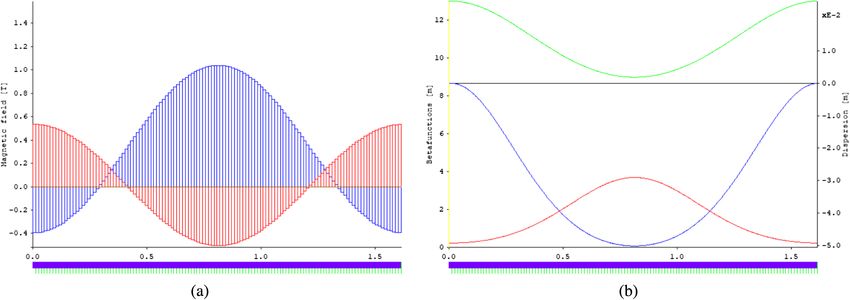
FIG. 15. Properties of the Mathieu cell for the SLS 2.0 example as computed by OPA. (a) Pole-tip fields for multipole slices
(cf. Fig. 14). Only fields for multipoles of finite length (dipole: blue, quadrupole: red) are shown. (b) optical functions of optimized
Mathieu cell for SLS 2.0 in opa (βx : blue, βy : red, η: green).
031601-11B. RIEMANN PHYS. REV. ACCEL. BEAMS 24, 031601 (2021)
TABLE II. Lattice parameters of the Mathieu cell for the SLS ACKNOWLEDGMENTS
2.0 example as computed by OPA. Rounded values have been
used where appropriate. The author thanks M. Kranjčević, J. Kallestrup, A.
Streun, and J. Bengtsson for improving the manuscript
Parameter Value by proofreading and/or hinting at useful references.
Cell length 1.6140 m Furthermore, the author appreciates the general support
Horizontal cell tune νx 0.45057 of M. Aiba, M. Böge, J. Chrin, and T. Schietinger.
Vertical cell tune νy 0.34988
Natural horizontal cell chromaticity ξx −1.84995 APPENDIX A: PROPERTIES OF SCALED
Natural vertical cell chromaticity ξy −0.67107 BESSEL FUNCTION
Momentum compaction −2.718 × 10⁻⁶
Horizontal damping partition J x 1.8207 Using the series expansion of I n [41]
Beam energy 2.4 GeV
Radiated energy/cell passage 4.243 keV
X∞
ðx=2Þ2q
I n ðxÞ ¼ ðx=2Þn ðA1Þ
Natural energy spread 8.6422 × 10⁻⁴ q¼0
q!ðn þ qÞ!
Horizontal damping time 3.345 ms
Vertical damping time 6.090 ms
and the definition
Longitudinal damping time 5.164 ms
Horizontal emittance ϵx 33.19 pm
Dn ðk; xÞ ¼ I n ðkxÞ=ðk=2Þn ; ðA2Þ
I1 integrated over cell −4.387 × 10⁻⁶ m
I2 integrated over cell 9.084 × 10⁻³ m−1 one obtains
I3 integrated over cell 9.467 × 10⁻⁴ m−2
I4 integrated over cell −7.455 × 10⁻³ m−1 X
∞
x2q
I5 integrated over cell 6.495 × 10⁻⁸ m−1 Dn ðk; xÞ ¼ xn ðk=2Þ2q : ðA3Þ
q¼0
q!ðn þ qÞ!
VII. CONCLUSION Note that a removable singularity exists at k ¼ 0,
In this work, we introduced Mathieu unit cells as lim Dn ðk; xÞ ¼ xn =n!: ðA4Þ
elementary approximations for periodic lattice systems. k→0
Due to their distributed multipolar structure, they allow for
the inclusion of combined-function effects, as well as the The derivative, required for the radial component of field
computation of common figures of merit like momentum density, can be expressed as a series in k,
compaction and emittance. They even predict the useful-
dDn ðk; xÞ X∞
x2q
ness of combining longitudinal gradients with reverse ¼ xn−1 ð2q þ nÞ
bending, and reach sub-TME emittance. dx q¼0
q!ðn þ qÞ!
By its nature, the goal of this study can only be to
illuminate an “undercurrent” of the sinusoidal focusing xn−1 k 2 xnþ1
¼n þ ð2 þ nÞ þ…
concept, permeating lattice design, that otherwise is n! 2 ðn þ 1Þ!
concealed by practical requirements of accelerator tech- xn−1 nþ2
nology. It goes without saying that a realizable lattice ¼ 1 þ k2 x2 þ : ðA5Þ
ðn − 1Þ! 4nðn þ 1Þ
design requires detailed studies incorporating a multitude
of boundary conditions [28,31] e.g., dynamic aperture
considerations, robustness in case of field deviations
APPENDIX B: SCALING CELL LENGTH
[32,33], which depend on the cell length in a nontrivial
IN A FIXED ARC
manner.
Mathieu cells are useful tools for investigating To obtain results as general as possible, this work often
basic lattice configurations and performance limits. uses multipoles normalized to a dimensionless unit cell. A
Sinusoidal bending forces are commonly used in the rule is that the standard, rigidity-normalized multipole
description of undulator fields (see, e.g., [14]). In the fields—1=ρ for curvature, κ for quadrupole focusing
context of further progress on MBA miniaturization and strength, μ for sextupole strength—are denoted by
combined-function magnet lattices, e.g., [34–37], the con- Greek letters. Their cell-normalized, dimensionless coun-
cept of Mathieu cells could thus help to shape future lattice terparts—b for normalized curvature, k for normalized
designs. quadrupole, m for normalized sextupole strength, are
The source code for all computations in this work, denoted by Latin letters.
excluding the ones performed in OPA, is based on the The dimensionless, cell-normalized optics functions are
SciPy framework [38,39] and fully accessible [40]. also denoted with a tilde, •˜, to distinguish them from the
031601-12MATHIEU UNIT CELL AS A TEMPLATE FOR LOW … PHYS. REV. ACCEL. BEAMS 24, 031601 (2021)
Z 4 Z
standard optics functions. All occurring synchrotron inte- L
βðuÞηðuÞμðuÞds ¼ h1=ρi β̃ðuÞη̃ðuÞμðuÞ
grals I • are cell-normalized. π
When replacing the path length s by a scaled path length
¼ const: ðB8Þ
u ¼ πs=L, we require the scaled solution xðuÞ to fulfill
Hill’s equation (4)
Then sextupole strength scales as
d2 4
xðuÞ þ κðuÞxðuÞ ¼ 0; ðB1Þ π mðuÞ
ds2 μðuÞ ¼ : ðB9Þ
L h1=ρi
so that Note that this inverse quartic scaling is due to the average
curvature h1=ρi remaining constant—if the ring was
d2 miniaturized as a whole, h1=ρi ∝ 1=L would hold, result-
xðuÞ þ ½ðL=πÞ2 κðuÞxðuÞ ¼ 0 ðB2Þ
du2 ing in inverse cubic scaling and corresponding to the
multipole order.
and by comparison
2 APPENDIX C: FIELDS IN THE
π
κðuÞ ¼ kðuÞ; ðB3Þ MACHINE PLANE
L
We are interested in the field density in the machine
resulting in the standard quadrupole strength scaling with plane, given by Eq. (48)
the inverse square of cell length.
Since we require the tune for all cells to be independent X
3 X
2
Dn ðk̄p ; xÞ
of the cell length, this By ðx; sÞ ¼ V n;p n cosðk̄p sÞ; ðC1Þ
R should also apply to the natural n¼1 p¼0
x
chromaticity so that βκ ds ∝ β=L is constant, and
specifically its series expansion in x, yielding the multipole
L
βðuÞ ¼ β̃ðuÞ ðB4Þ components. Inserting Eq. (A3) into Eq. (C1), one obtains
π an approximation for small x as
R
is linear in L, so β̃k ds is also constant, with β̃ being the X
2
cell-normalized optics function. By ðx;sÞ ¼ cosðk̄p sÞ·
Furthermore, the dispersion function ηðsÞ must fulfill the p¼0
inhomogeneous Hill’s equation 2 x2 3
· V 1;p þ V 2;p x þ ðV 3;p þ V 1;p k̄p =4Þ þ Oðx Þ :
2
d2
1=ρðuÞ ¼ ηðuÞ þ κðuÞηðuÞ: ðB5Þ ðC2Þ
ds2
Utilizing that k̄0 ¼ 0, and that the dipolar and quad-
As the average arc curvature should remain constant, we
rupolar fields are set to zero for the p ¼ 2 harmonic
require bðuÞ to be independent of cell length. Division by
(V 3;1 ¼ V 3;2 ¼ 0), we can simplify this series to
h1=ρi yields
By ðx;sÞ
d2 ηðuÞ ηðuÞ
bðuÞ ¼ 2 þ κðuÞ ¼ V 1;0 þ V 1;1 cosðk̄1 sÞ þ ½V 2;0 þ V 2;1 cosðk̄1 sÞx
ds h1=ρi h1=ρi 2
d2 k̄21 x
¼ η̃ðuÞ þ kðuÞη̃ðuÞ ðB6Þ þ V 3;0 þ V 3;1 þ V 1;1 cosðk̄1 sÞ þ V 3;2 cosðk̄2 sÞ
du2 4 2
þ Oðx3 Þ: ðC3Þ
with
For almost all coefficients V, we find that each is
2
π ηðuÞ proportional to a dipolar, quadrupolar, or sextupolar focus-
η̃ðuÞ ¼ : ðB7Þ ing term. The only exception is the quadratic coefficient
L h1=ρi
k̄21
For the compensated chromaticity to be independent of cell V 3;1 þ V 1;1 ; ðC4Þ
length, we require 4
031601-13B. RIEMANN PHYS. REV. ACCEL. BEAMS 24, 031601 (2021)
feeding up the dipolar fringe effect via the V 1;1 coefficient. [9] J. P. Delahaye and J. P. Potier, Reverse bending magnets in
To quantify its effect, we define a fringe factor a combined function lattice for the clic damping ring, in
Proc. 1989 Particle Accelerator Conf., Chicago (1989)
k̄21 V 1;1 π 2 V 1;1 p. 1611.
f¼ ¼ ; ðC5Þ [10] E. D. Courant, Accelerators, colliders, and snakes, Annu.
4 V 3;1 L2 V 3;1 Rev. Nucl. Part. Sci. 53, 1 (2003).
[11] A. Streun, The anti-bend cell for ultralow emittance storage
so that ring lattices, Nucl. Instrum. Methods Phys. Res., Sect. A
737, 148 (2014).
d2 By [12] B. Riemann and A. Streun, Low emittance lattice design
ð0; sÞ ¼ V 3;0 þ V 3;1 ð1 þ fÞ cosðk̄1 sÞ
dx2 from first principles: Reverse bending and longitudinal
gradient bends, Phys. Rev. Accel. Beams 22, 021601 (2019).
þ V 3;2 cosðk̄2 sÞ: ðC6Þ [13] T. Zhang and X. Huang, Numerical optimization of a low
emittance lattice cell, Nucl. Instrum. Methods Phys. Res.,
And, by using Eq. (36) and Eq. (B9), Sect. A 923, 55 (2019).
[14] K. Wille, The Physics of Particle Accelerators (Oxford
mðuÞ ¼ m0 þ 2m̄1 ð1 þ fÞ cosð2uÞ þ 2m2 cosð4uÞ; ðC7Þ University Press, New York, 2000).
[15] N. Christofilos, Focussing system for ions and electrons,
with m̄1 being the sextupole coefficient set when ignoring (1950), US Patent 2736799A.
the fringe effect (f ¼ 0), and [16] J. D. Jackson, Classical Electrodynamics, 3rd ed. (Wiley,
New York, 1999).
[17] G. W. Hill, On the part of the motion of the lunar perigee
m1 ¼ m̄1 ð1 þ fÞ: ðC8Þ
which is a function of the mean motions of the sun and
moon, Acta Math. 8, 1 (1886).
Again by connecting the V coefficients in f to the b and m [18] E. D. Courant and H. S. Snyder, Theory of the alternating-
components via Eq. (36) and Eq. (B9), one obtains gradient synchrotron, Ann. Phys. (N.Y.) 281, 1 (1958).
2 [19] J. E. Sträng, On the characteristic exponents of Floquet
Lh1=ρi 2 b1 θ b1 solutions to the Mathieu equation, Acad. Roy. Belg. Bull.
f¼− ¼− : ðC9Þ
π m̄1 π 2m̄1 Cl. Sci. 16, 269 (2005), arXiv:math-ph/0510076.
[20] Carmen Chicone, Ordinary Differential Equations with
Applications (Springer, New York, 2006).
[21] S. A. Wilkinson, N. Vogt, D. S. Golubev, and J. H. Cole,
Approximate solutions to Mathieu’s equation, Phys. E 100,
24 (2018).
[1] R. Chasman, G. K. Green, and E. M. Rowe, Preliminary [22] H. Wiedemann, Particle Accelerator Physics, 4th ed.
design of a dedicated synchrotron radiation facility, IEEE (Springer, New York, 2015).
Trans. Nucl. Sci. 22, 1765 (1975). [23] B. Riemann, The bilinear-exponential closed-orbit model
[2] G. Vignola, Preliminary design of a dedicated 6 GeV and its application to Storage Ring beam diagnostics, Ph.D.
synchrotron radiation storage ring, Nucl. Instrum. Methods thesis, TU Dortmund University, 2016, chapter 2.
Phys. Res., Sect. A 236, 414 (1985). [24] R. H. Helm, M. J. Lee, P. L. Morton, and M. Sands,
[3] D. Einfeld and M. Plesko, A modified qba optics for low Evaluation of synchrotron radiation integrals, IEEE Trans.
emittance storage rings, Nucl. Instrum. Methods Phys. Nucl. Sci. 20, 900 (1973).
Res., Sect. A 335, 402 (1993). [25] M. Sands, The Physics of Electron Storage Rings: An
[4] M. Sommer, Optimization of the Emittance of electrons Introduction, Tech. Rep. No. R-121 (SLAC, 1979) with
(positrons) storage rings, Tech. Rep. No. LAL/RT/83-15 addendum.
(Laboratoire de l’Accélérateur Linéaire, 1983). [26] S. M. Liuzzo, D. Einfeld, L. Farvacque, and P. Raimondi,
[5] L. C. Teng, Minimum emittance Lattice for Synchrotron Hybrid Multi Bend Achromat at 3 GeV for future 4th
Radiation Storage Rings, Tech. Rep. No. LS-17 (Argonne generation light sources, in Proc. 7th Int. Particle Accelerator
National Laboratory, 1985). Conf. (IPAC’16), Busan (JACoW, Geneva, 2016), p. 2822.
[6] R. Nagaoka and A. F. Wrulich, Emittance minimisation [27] J. Bengtsson, Ultra Low Emittance Light Sources, in Proc.
with longitudinal dipole field variation, Nucl. Instrum. 11th European Particle Accelerator Conference, Genoa,
Methods Phys. Res., Sect. A 575, 292 (2007). Italy (EPS-AG, Genoa, Italy, 2008), p. 988.
[7] A. Streun and A. Wrulich, Compact low emittance [28] Y. Cia, W. Chou et al., ICFA Beam Dynamics Newsletter
light sources based on longitudinal gradient bending 57: Low emittance rings (2012), https://icfa-usa.jlab.org/
magnets, Nucl. Instrum. Methods Phys. Res., Sect. A archive/newsletter.shtml.
770, 98 (2015). [29] OPA accelerator optics software, https://ados.web.psi.ch/
[8] M. A. D. Martinez, F. Toral, H. Ghasem, P. S. Papadopou- opa (2017).
lou, and Y. Papaphilippou, Longitudinally variable field [30] A. Streun, T. Garvey, L. Rivkin, V. Schlott, T. Schmidt, P.
dipole design using permanent magnets for clic damping Willmott, and A. Wrulich, SLS-2—the upgrade of the
rings, IEEE Trans. Appl. Supercond. 28, 1 (2018). Swiss Light Source, J. Synchrotron Radiat. 25, 631 (2018).
031601-14MATHIEU UNIT CELL AS A TEMPLATE FOR LOW … PHYS. REV. ACCEL. BEAMS 24, 031601 (2021)
[31] P. Emma and T. Raubenheimer, Systematic approach to storage ring light source, Nucl. Instrum. Methods Phys.
damping ring design, Phys. Rev. Accel. Beams 4, 021001 Res., Sect. A 943, 162506 (2019).
(2001). [37] G. Wang, T. Shaftan, V. Smaluk, Y. Hidaka, O. Chubar, T.
[32] J. Bengtsson, Robust design of low emittance rings, in Low Tanabe, J. Choi, S. Sharma, C. Spataro, and N. A.
Emittance Rings workshop 2014, Frascati (2014). Mesentsev, Complex bend. II. A new optics solution,
[33] J. Bengtsson and A. Streun, Robust Design Strategy for Phys. Rev. Accel. Beams 22, 110703 (2019).
SLS-2, Paul Scherrer Institut Tech. Report No. SLS2- [38] P. Virtanen, R. Gommers, T. E. Oliphant et al., SciPy 1.0–
BJ84-001, 2017. Fundamental Algorithms for Scientific Computing in
[34] A. V. Bogomyagkov, E. B. Levichev, and S. V. Sinyatkin, Python, arXiv:1907.10121.
Weak focusing low emittance storage ring with large 6d [39] J. D. Hunter, Matplotlib: A 2D graphics environment,
dynamic aperture based on canted cosine theta magnet Comp. Sci. Eng. 9, 90 (2007).
technology, arXiv:1906.09692. [40] B. Riemann, Elementary computations for studying Mathieu
[35] P. T. Tavares, Long term plans at MAX IV, in 2nd work- unit cells, (2020), https://github.com/b-riemann/mathieu-cell.
shop on low emittance ring lattice design (2016). [41] M. Abramovitz and I. Stegun, Handbook of Mathematical
[36] P. Yang, Z. Bai, T. Zhang, D. Xu, and L. Wang, Design of a Functions, 10th ed. (National Bureau of Standards, Gai-
hybrid ten-bend-achromat lattice for a diffraction-limited thersburg, Maryland, U.S.A., 1972).
031601-15You can also read