Stability Characteristics of Wing Span and Sweep Morphing for Small Unmanned Air Vehicle: A Mathematical Analysis
←
→
Page content transcription
If your browser does not render page correctly, please read the page content below
Hindawi
Mathematical Problems in Engineering
Volume 2020, Article ID 4838632, 15 pages
https://doi.org/10.1155/2020/4838632

Research Article
Stability Characteristics of Wing Span and Sweep Morphing for
Small Unmanned Air Vehicle: A Mathematical Analysis

 Hafiz Muhammad Umer,1 Adnan Maqsood ,1 Rizwan Riaz,1 and Shuaib Salamat2
 1
 Research Centre for Modeling & Simulation, National University of Sciences & Technology, Islamabad 44000, Pakistan
 2
 College of Aeronautical Engineering, National University of Sciences & Technology, Islamabad 44000, Pakistan

 Correspondence should be addressed to Adnan Maqsood; adnan@rcms.nust.edu.pk

 Received 11 March 2020; Revised 22 May 2020; Accepted 6 June 2020; Published 3 July 2020

 Academic Editor: Daniela Addessi

 Copyright © 2020 Hafiz Muhammad Umer et al. This is an open access article distributed under the Creative Commons
 Attribution License, which permits unrestricted use, distribution, and reproduction in any medium, provided the original work is
 properly cited.
 Morphing aircraft are the flight vehicles that can reconfigure their shape during the flight in order to achieve superior flight
 performance. However, this promising technology poses cross-disciplinary challenges that encourage widespread design
 possibilities. This research aims to investigate the flight dynamic characteristics of various morphed wing configurations
 that can be incorporated in small-scale UAVs. The objective of this study was to analyze the effects of in-flight wing sweep
 and wingspan morphing on aerodynamic and flight stability characteristics. Longitudinal, lateral, and directional
 characteristics were evaluated using linearized equations of motion. An open-source code based on Vortex Lattice Method
 (VLM) assuming quasi-steady flow was used for this purpose. Trim points were identified for a range of angles of attack in
 prestall regime. The aerodynamic coefficients and flight stability derivatives were compared for the aforementioned
 morphing schemes with a fixed-wing counterpart. The results indicated that wingspan morphing is better than wing sweep
 morphing to harness better aerodynamic advantages with favorable flight stability characteristics. However, extension in
 wingspan beyond certain limits jeopardizes the advantages. Dynamically, wingspan and sweep morphing schemes behave
 in an exactly opposite way for longitudinal modes, whereas lateral-directional dynamics act in the same fashion for both
 morphing schemes. The current study provided a baseline to explore the advanced flight dynamic aspects of employed wing
 morphing schemes.

1. Introduction researchers to look for versatile morphing configurations
 [5–7]. It refers to the changing wing planform by varying
The role of Unmanned Air Vehicles (UAVs) in uncon- wing geometric parameters like span, sweep angle, dihedral
ventional and asymmetric military roles as well as diversified angle, chord length, wing twist, and airfoil shape modifi-
civil environments is on the rise. UAVs are designed to meet cation [8–10]. Among these versatile morphing schemes,
conflicting mission requirements with dynamic on-board wingspan, sweep angle, and wing dihedral are the most
reconfiguration capabilities. The conventional fixed-wing influential wing parameters toward the performance and
aircraft design puts severe flight limitations to operate in a stability of the aircraft [11–13].
diverse set of mission requisites. Wing morphing is at- Wingspan and sweep angle mainly affect the wing
tributed as a potential approach to significantly affect the planform. These are the most important morphing param-
aerodynamic characteristics of a flying vehicle during flight eters that can greatly affect the aircraft’s flight dynamics. Both
[1, 2]. The motivation behind wing morphing comes from wingspan and sweep angle can be adjusted to control the wing
the birds that change their wings’ configuration to attain aspect ratio in order to modify lift-to-drag ratio, lift-curve
suitable aerodynamic profile for various flight conditions slope, the inertia of the aircraft, and other forces depending on
[3, 4]. Wing morphing technology, although not new, in the wing area. Thus, both the performance and stability of the
conjunction with smart materials has renewed the interest of aircraft can be improved by increasing the wing aspect ratio
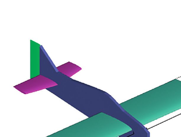
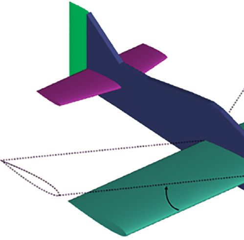
2 Mathematical Problems in Engineering

[14]. For span variation, inflatable telescopic wing design is validation through wind tunnel testing, which is generally not
normally a preferred choice as it has the ability to undergo a attempted during morphing studies. An appropriate structural
114% change [15] in aspect ratio while supporting aerody- design is essential which can withstand the aerodynamic load
namic loads. Blondeau et al. [15] performed a study of the conditions along with morphing capabilities. Therefore,
inflatable telescopic wing with three different degrees of weight penalty is a side challenge for the development of small
extension in the wind tunnel and compared it with the fixed morphing wing aircraft.
wing of the same wingspan. Their results conclude that a high The improvement in aerodynamic performance with in-
lift-to-drag ratio is achievable by extending the telescopic flight morphing results in altering flight dynamic charac-
wing but observed less lift-to-drag ratio compared with the teristics of UAVs [23–28]. Small UAVs are characterized by
fixed wing of the same span as parasite drag increases due to low moment of inertias. Any change in the geometric
the seams between the wing sections. configuration results in pronounced variations in the flight
 Similarly, an increase/decrease in sweep angles causes stability characteristics. This warrants the need of investi-
corresponding changes in aerodynamic parameters [16]. gation of variation in flight stability characteristics as a result
Wings with a higher sweep angle are more advantageous in of wing morphing. Aircraft fight stability concerns are
attaining the highest maximum speed (dash) while the smaller typically assumed to be regulated by Automatic Flight
wing sweep angle was more suitable for higher range and Control System (AFCS). This assumption has made several
endurance for loiter/reconnaissance missions. Recently, a sophisticated designs unfeasible for the fact that control
performance and flight dynamic study of a variable-sweep architectures need an underlying dynamic model. These
wing was conducted by Kong [17] and Chong [18], respec- issues are especially aggravated during the transitional
tively. Kong performed trim calculations for specific velocities morphing phase. Therefore, accurate prediction about the
and angles of attack to discuss various performance and dynamic efficiency of aircraft, morphing limits, and reliance
stability characteristics while Chong investigated the same of aircraft’s stability on wing morphing parameters is es-
stuff performing trim analysis for particular cruise speeds and sential during the preliminary design stage. The stability
altitudes. Both these researchers outlined suitable mission analysis of a small-scale UAV under two different wing
paths for optimal performance according to their respective symmetric morphing schemes (variable span and sweep
morphing schemes. Prabhakar et al. [19] discussed the lon- angle) is the contribution of the present work.
gitudinal dynamics of morphing aircraft with variable wing- In this paper, geometric details of UAV and mathe-
span and sweep by trimming the aircraft for specific speeds matical model used for the dynamic evaluation are discussed
and altitudes. Computation of aerodynamic coefficients and first. It is followed by aerodynamic data generation using
stability analysis were performed using Vortex Lattice Method panel methods. Subsequently, the results are discussed in
(VLM) code in researches referenced as [17–19]. terms of trim conditions, static stability, and aircraft dy-
 Wing morphing is a complex phenomenon and invokes namic modes for both (variable wingspan and sweep angle)
interdisciplinary challenges. Along with aerodynamic feasi- morphing schemes. The current research is aimed at the
bility, various structural, mechanical, and flight dynamic feasibility study of different morphing concepts for a small-
stability challenges have made this technology more depen- scale UAV from flight dynamic perspective.
dent and complicated. In order to change the wing shape, an
appropriate mechanism is required which best suits the 2. Problem Formulation
aerodynamic profile of the aircraft. Usually, actuators are
required in the internal mechanism to change the wing shape. 2.1. Geometric Modeling. The aircraft considered for the
This mechanism must be covered with flexible or sliding dynamic evaluation is a standard wing-tail configuration
aerodynamic surfaces capable of having load-transfer at- made up of extended polypropylene with carbon-fiber rods
tachments. A complicated mechanism of series of actuators used for reinforcement. The model has a fuselage length and
and flexible materials is required to construct a morphing wingspan of 0.84 m and 1 m, respectively. The aspect ratio of
wing. Actuator requirements for a controlled morphing air- the wings is 4.31. The model of aircraft with baseline and
craft were presented by Inman [20] which discusses the design extreme geometric configurations is overlaid in Figure 1.
mechanism for the range of motion, concerns about binding Typical dimensional attributes of baseline configuration are
and friction, the effects of wing structural deformability under shown in Table 1. The baseline configuration has no sweep
load, and the control of the actuator stroke under load. and wingspan of 1.00 m. The wing area used to calculate
Generally, a successful wing morphing system must be able to aerodynamic coefficients is 0.24 m2 of baseline configura-
overcome the aerodynamic load shifting (due to the change in tion. The leading edges of wing, elevator, and center of
aerodynamic center of aircraft during morphing) as well as the gravity are located at 0.12 m, 0.7 m, and 0.2 m, respectively.
weight penalty of added mechanical systems. Tarnowski and For wingspan and sweep morphing, various mechanisms
Goetzendorf-Grabowski [21] and Tarnowski [22] presented a are suggested in different studies [15, 29–35]. For span
novel concept of wing morphing that circumvented the issue morphing, the existing wingspan of 1 m can go up to 1.4 m.
of elastic deformation. The interesting part of the study was its For sweep morphing, the wings can be swept between 0° and
Mathematical Problems in Engineering 3

 Z
 X

 Y

 m r = 30°
 .7
 =0
 b/2

 m
 0.5
 m
 0.2
 (a) (b)

 Figure 1: Aircraft baseline model with extreme morphing states: span morphing (a) and sweep morphing (b).

 Table 1: Model parameters. developed using steady VLM. For dynamic modeling, lin-
 earized six Degree of Freedom (6-DoF) rigid body equations
Parameter name Value
 of motion framework were used to accomplish stability and
Wingspan 1.00 m control analysis. Underlying design configurations were
Wing chord 0.24 m
 built and analyzed through an open source three-dimen-
Wing area 0.24 m2
Aspect ratio 4.17 sional VLM code named XFLR5 [40, 41]. In order to simplify
Taper ratio 1.0 the aircraft dynamics, the effects of morphing motion are
Wing sweep (˄) 0° neglected assuming quasi-static morphing. Therefore,
Wing dihedral 0° aerodynamic and stability analyses were performed by
Wing LE position (0.12, 0, 0) m morphing aircraft’s wings from one configuration to the
Wing, elevator airfoil NACA 0012 other enabling a simple prototype to be built.
Fuselage length 0.84 m Aerodynamic evaluation of the UAV was performed at
Elevator LE position (0.7, 0, 0.01) m 15 m/s in the prestall regime (angles of attack varied from 0°
Elevator root chord 0.14 m to 20°). The effect of span and sweep morphing on the
Elevator tip chord 0.1 m
 coefficient of lift, drag, and pitching moment is shown in
Elevator area 0.05 m2
Vertical fin area 0.02 m2
 Figures 2–4. The wing area is kept the same during com-
Tail volume 0.054 putation of aerodynamic coefficients to baseline value, that
Total mass 0.495 kg is, 0.24 m2. It should be noted that the stall characteristics
Center of gravity (0.2, 0, 0.1) m cannot be accurately captured due to the limitation of VLM.
 Therefore, the current findings are only valid in the low angle
 of the attack range. The increase in the wingspan result is
30°. The effect of span morphing on change in the center of nominal increase in coefficient of lift; however, the mini-
gravity was calculated and found to be negligible. Similarly, mum change is observed due to the wing sweep variation.
the effect of sweep morphing on the change in wing area was For the coefficient of drag, the effects of sweep and span
negligible. variation are not significant. It should be noted that various
 studies primarily focus on aerodynamic evaluation of
 morphing behavior; however, it will be seen ahead in the
2.2. Aerodynamic and Flight Dynamic Modeling. Various paper that morphing has more pronounced effect on sta-
analytical models and computational techniques [36–39] bility than aerodynamic characteristics.
with varying degrees of accuracy and computation time can Pitching moment coefficient, a primary indicator for
be used to model the aircraft’s aerodynamics. In the present longitudinal static stability, is plotted in Figure 4 for both
work, such an aerodynamic model was required which can morphing schemes. Wingspan extension results in a de-
predict forces and moments of the aircraft in less compu- crease in longitudinal static stability whereas the increase
tational time. Thus, Vortex Lattice Method (VLM) [39] is in sweep angle increases longitudinal static stability. The
assumed to be the best choice of aerodynamic modeling at pitching moment is computed around the center of gravity
the preliminary design phase. Numerical models of aircraft of aircraft. For span morphing case, a stability reversal
aerodynamics for various wing configurations were around 15° angle of attack is observed for the maximum
4 Mathematical Problems in Engineering

 1.5 1.5

 1 1
 CL

 CL
 0.5 0.5

 0 0
 0 2 4 6 8 10 12 14 16 18 20 0 2 4 6 8 10 12 14 16 18 20
 α (degrees) α (degrees)

 b = 1.0 m b = 1.3 m Λ = 0° Λ = 20°
 b = 1.1 m b = 1.4 m Λ = 5° Λ = 25°
 b = 1.2 m Λ = 10° Λ = 30°
 Λ = 15°
 (a) (b)

 Figure 2: Lift coefficients for wingspan (a) and wing sweep (b) morphing at fixed speed with varying angles of attack.

 0.15 0.15

 0.1 0.1
 CD
 CD

 0.05 0.05

 0 0
 0 2 4 6 8 10 12 14 16 18 20 0 2 4 6 8 10 12 14 16 18 20
 α (degrees) α (degrees)

 b = 1.0 m b = 1.3m Λ = 0° Λ = 20°
 b = 1.1m b = 1.4m Λ = 5° Λ = 25°
 b = 1.2m Λ = 10° Λ = 30°
 Λ = 15°
 (a) (b)

 Figure 3: Drag coefficients for wingspan (a) and wing sweep (b) morphing at fixed speed with varying angles of attack.

span configuration. This suggests that the span moves a The said model is conveniently expressed in the form of
neutral point of the aircraft forward (toward aircraft nose) state space as
whereas sweep moves a neutral point of the aircraft x_ � Ax + Bu, (1)
backward.
 The standard practice to establish the flight dynamic where A is the system matrix, x is the state vector, containing
model of a conventional aircraft is to derive rigid body variables describing the state of the system, B is the input
equations of motion which can effectively predict aircraft’s matrix, and u is the input vector, containing input variables
translational and rotational dynamics [42]. In this paper, (usually thrust and control surfaces deflections). Lateral/
UAV dynamics is represented by an elaborate 6-DoF directional controls (ailerons and rudder) remain neutral
model (refer to equations (2) and (3)) which is linearized throughout the analysis; therefore, input vector is zero for
under the assumptions of steady state flight conditions. lateral-directional dynamics:
Mathematical Problems in Engineering 5

 0 0

 −0.1
 −0.02
 −0.2
 Cm

 Cm
 −0.3
 −0.04

 −0.4

 −0.06 −0.5
 0 2 4 6 8 10 12 14 16 18 20 0 2 4 6 8 10 12 14 16 18 20
 α (degrees) α (degrees)
 b = 1.0 m b = 1.3 m Λ = 0° Λ = 20°
 b = 1.1 m b = 1.4 m Λ = 5° Λ = 25°
 b = 1.2 m Λ = 10° Λ = 30°
 Λ = 15°
 (a) (b)

Figure 4: Pitching moment (with respect to CG) coefficients for wingspan (a) and wing sweep (b) morphing at fixed speed with varying
angles of attack.

 Xu Xw
 ⎢
 ⎡
 ⎢ 0 − g cos θ0 ⎤⎥⎥
 ⎢
 ⎢
 ⎢ m m ⎥⎥⎥
 ⎢
 ⎢
 ⎢ ⎥⎥⎥
 ⎢
 ⎢
 ⎢ ⎥⎥⎥
 u_ ⎢
 ⎢
 ⎢ ⎥⎥⎥ u
 ⎢
 ⎡
 ⎢
 ⎢ ⎥
 ⎤
 ⎥
 ⎥ ⎢
 ⎢
 ⎢ Z u Z w
 Z q + mu 0 − mg sin θ 0
 ⎥⎥⎥⎡⎢⎢⎢ ⎤⎥⎥⎥
 ⎢
 ⎢
 ⎢ ⎥⎥⎥ ⎢ ⎢
 ⎢ ⎥⎥⎥⎢⎢⎢ ⎥⎥⎥
 ⎢
 ⎢
 ⎢ ⎥
 w_ ⎥⎥⎥ ⎢ ⎢
 ⎢ m − Zw_ m − Zw_ m − Zw_ m − Zw_ ⎥⎥⎥⎢⎢⎢ w ⎥⎥⎥
 ⎢
 ⎢
 ⎢ ⎥
 ⎥ ⎢
 ⎢
 ⎢ ⎥⎥⎥⎢⎢⎢ ⎥⎥⎥
 ⎢
 ⎢
 ⎢ ⎢
 ⎥⎥ � ⎢
 ⎢ ⎥⎥⎥⎢⎢⎢ ⎥⎥⎥
 ⎢
 ⎢ ⎥
 ⎥
 ⎥ ⎢
 ⎢
 ⎢ ⎥⎥⎥⎢⎢⎢ ⎥⎥⎥
 ⎢
 ⎢
 ⎢ q_ ⎥⎥ ⎢ ⎥ ⎢ ⎥⎥⎢⎢ q ⎥⎥
 ⎢
 ⎢
 ⎣ ⎦ ⎢ ⎥
 ⎥ ⎢
 ⎢
 ⎢
 ⎢ 1 Mw_ Zu 1 Mw_ Zw 1 ⎛
 ⎝
 M w_ Z q + mu
 0 ⎠
 ⎞ Mw_ mg sin θ0 ⎥⎥⎥⎥⎥⎢⎢⎢⎣ ⎥⎥⎥⎦
 ⎢
 ⎢ M + M + M + − ⎥⎥
 θ_ ⎢
 ⎢
 ⎢
 ⎢ Iyy u
 m − Zw_ Iyy w
 m − Zw_ Iyy q
 m − Zw_ Iyy m − Zw_ ⎥⎥⎥⎥⎥ θ
 ⎢
 ⎢
 ⎢ ⎥⎥⎥
 ⎢
 ⎢
 ⎢ ⎥⎥⎦
 ⎣
 0 0 1 0
 (2)
 Xδ e
 ⎢
 ⎡
 ⎢
 ⎢ ⎤⎥⎥⎥
 ⎢
 ⎢
 ⎢ m ⎥⎥⎥
 ⎢
 ⎢
 ⎢ ⎥⎥⎥
 ⎢
 ⎢
 ⎢ ⎥⎥⎥
 ⎢
 ⎢
 ⎢ ⎥⎥⎥
 ⎢
 ⎢
 ⎢ Z δ ⎥⎥⎥
 ⎢
 ⎢
 ⎢
 e
 ⎥⎥⎥
 ⎢
 ⎢
 ⎢ m − Z ⎥⎥⎥
 ⎢
 +⎢
 ⎢
 w_ ⎥⎥⎥ δ ,
 ⎢
 ⎢ ⎥⎥⎥ e
 ⎢
 ⎢
 ⎢ ⎥⎥⎥
 ⎢
 ⎢
 ⎢ ⎥⎥⎥
 ⎢
 ⎢ 1 M w_ Z δ ⎥⎥⎥
 ⎢
 ⎢
 ⎢ M + e
 ⎥
 ⎢
 ⎢
 ⎢
 ⎢ I yy
 δ e
 m − Zw_ ⎥⎥⎥⎥⎥
 ⎢
 ⎢
 ⎢ ⎥⎥⎥
 ⎢
 ⎢
 ⎣ ⎥⎦
 0

 Yv Yp Yr
 ⎢
 ⎡
 ⎢
 ⎢ − u0 g cos θ0 ⎤⎥⎥⎥
 ⎢
 ⎢
 ⎢ m m m ⎥⎥⎥
 ⎢
 ⎢
 ⎢ ⎥⎥⎥
 v_ ⎢
 ⎢
 ⎢ Lp ⎥⎥⎥ v
 ⎢
 ⎡ ⎤⎥⎥⎥ ⎢ ⎢ Lv ∗ ∗ Lr ∗ ⎥⎥⎥⎡⎢⎢ ⎤⎥⎥
 ⎢
 ⎢
 ⎢ _ ⎥ ⎢
 ⎢
 ⎢ + Ixz Nv ∗ + Ixz Np + I N 0 ⎥⎥⎢⎢⎢ p ⎥⎥⎥
 ⎢
 ⎢ p ⎥
 ⎥ ⎢
 ⎢
 ⎢ I ∗ I ∗
 Ix xz r ⎥⎥⎥⎢⎢ ⎥⎥
 ⎢
 ⎢
 ⎢ ⎥
 ⎥
 ⎥ � ⎢
 ⎢ x x ⎥⎥⎥⎢⎢⎢ ⎥⎥⎥, (3)
 ⎢
 ⎢ ⎥ ⎢ ⎥⎥⎥⎢⎣ r ⎥⎦
 ⎣ r_ ⎥⎦ ⎢
 ⎢ ⎢
 ⎢
 ⎢ ⎥⎥⎥
 ⎢
 ⎢ Nv ∗ Np Nr
 ϕ_ ⎢
 ⎢
 ⎢
 ⎢
 ⎢ I ∗
 xz Lv + ∗
 Ixz Lp + ∗
 Ixz Lr + ∗ 0 ⎥⎥⎥⎥⎥ ϕ
 ⎢
 ⎢
 ⎢ Iz Iz∗ Iz ⎥⎥⎥
 ⎢
 ⎣ ⎥⎦
 0 1 tan θ0 0
6 Mathematical Problems in Engineering

where Ix∗ � (Ixx Izz − I2xz )/Izz ; Iz∗ � (Ixx Izz − I2xz )/Ixx ; control effort and a resulting decrease in elevator authority
 ∗
Ixz � Ixz /(Ixx Izz − I2xz ). Using the following relations, the to stabilize the aircraft can be observed by increasing
angle of attack α instead of vertical velocity w and side slip wingspan (refer to Figure 5(a)). The behavior manifests
angle β instead of side velocity v are approximated as desirable feature of wingspan morphing. Moreover, elevator
longitudinal and lateral-directional state variables, deflection requirements increase with the trim angle of
respectively: attack; however, that is a trivial requirement at high angle of
 w attack. Wing sweep morphing invokes two aerodynamic
 α≈ ; phenomena and reduces effective moment arm for elevator
 u0
 (4) due to aft center of pressure movement and alter the
 v spanwise lift distribution pattern on the wings. Therefore,
 β≈ .
 u0 the significant increase in elevator control effort by wing
 sweep morphing is indicated (Figure 5(b)).
 Figure 6 suggests that, for a particular wingspan, trim
 angle of attack reduces proportionally with trim velocity.
2.2.1. Aircraft Dynamic Modes. The UAV under discussion
 On the contrary, the increase in wingspan reduces trim
can typically exhibit five types of dynamic responses toward
 velocity requirements for the same trim angle of attack. It
longitudinal and lateral-directional perturbations which
 can be attributed to reduced thrust requirements as ad-
include three oscillatory (short period, phugoid, and Dutch
 ditional lift is provided from increased wing area. This
roll) modes and two nonoscillatory (roll subsidence and
 argument can be corroborated from Figure 2(a) where
spiral) modes. Frequency and damping of respective modes
 higher wingspan results in higher coefficient of lift. The
are approximated using the relations as summarized in
 increment is a result of increase in effective aspect ratio of
Table 2 [43, 44].
 the wings. In comparison with wingspan morphing, a
 In order to relate eigenvalues with the flying charac-
 significant increase in overall trim velocity can be observed
teristics, the period of oscillations, T, time to half the am-
 for swept wings’ configurations (refer to Figure 6(b)). The
plitude, T1/2, and time to double the amplitude, T2, are also
 increase in sweep angle typically results in a decrease in lift
calculated for oscillatory modes [45, 46]. The real part of the
 coefficient (refer to Figure 2(b)). Therefore, the trim ve-
eigenvalue is denoted by η and imaginary part by ω. It
 locity at lower angles of attack is higher for high swept
should be noted that the oscillatory modes are phugoid,
 configurations.
short period, and Dutch roll only:
 2π
 T≈ , (5)
 ω 3.2. Longitudinal Static Stability. A comparison of aircraft
 longitudinal static stability for both morphologies is pre-
 ln(2) sented in Figure 7. Both morphing schemes exhibit longi-
 T1/2 � − , for η < 0,
 η tudinally statically stable attributes over the entire range of
 (6)
 ln(2) trim states. However, it decreases with the increase in
 T2 � , for η > 0. wingspan and significantly declines for 1.4 m span config-
 η
 uration (Figure 7(a)). In case of sweep morphing, sub-
 The time to double or half the amplitude, T1/2 and T2, for stantially increasing pitch stiffness signifies the increase in
periodical modes, spiral and roll subsidence, is also calcu- longitudinal static stability for swept wings’ configurations
lated through equation (6). Aerodynamic forces and mo- (refer to Figure 7(b)). These results are substantively asso-
ments’ database is developed for all morphing states. Using ciated with the neutral point movement and, hence, static
6-DOF dynamic model presented in equations (2) and (3), margin of the aircraft that vary with the change in wings’
both longitudinal and lateral-directional dynamics are configuration. For span morphing, CG variation is trivial.
evaluated and stability derivatives are estimated based on However, in Figure 8(a), the downward shift along the
computed aerodynamic forces. For different span and sweep spanwise curves depicts the aft neutral point movement
angle variations, various trim states across a spectrum of toward CG, thus resulting in a decrease in static margin. A
angles of attack in prestall regime were evaluated for each reversing movement of neutral point (toward CG) along the
morphing scheme. Elevator trim deflections and trim ve- trim angles of attack can be observed for 1.4 m wingspan
locities are explored to investigate the equilibrium flight configuration. This can be correlated with the decrease in
conditions. Both static and dynamic stability characteristics longitudinal static stability in Figure 7(a). Wing sweep
are then analyzed based on linearization about trim states for morphing is followed by the change in neutral point due to
each morphing scheme. wings’ configuration. Figure 8(b) shows a reasonable in-
 crease in the resulting static margin due to the aft neutral
3. Results and Discussion point movement for sweep morphing. This variation of static
 margin justifies the trend of pitch stiffness of sweep
3.1. Trim Conditions for Wingspan and Sweep Morphing. morphing as shown in Figure 7(b). For sweep morphing, the
In Figure 5, variations in elevator trim deflections are plotted center of gravity moves from 0.2 m position at 0o sweep to
over a range of trim angles of attack for both wingspan and 0.236 m position at 30o sweep. The shift in CG is catered in
sweep morphing schemes. Significantly reduced elevator static margin calculation.
Mathematical Problems in Engineering 7

 Table 2: Aircraft dynamic modes approximation.
Mode name Frequency Damping Mode name Damping
Short period [Mq√ Z�w − Mα ]1/2 � w_ + Zw ]/2 ωsp
 − [Mq + u0√M Roll subsidence Lp
Phugoid 2 g/u0
 ������������������� 1/ 2(L/D) Spiral (Nr − Nv (Lr /Lv ))
Dutch roll (u0 Nv + Yv Nr − Nv Yr ) Nr + yv

 0 0

 −1 −5
 −10

 –δetrim (degrees)
 –δetrim (degrees)

 −2
 −15
 −3
 −20
 −4 −25
 −5 −30
 −6 −35
 0 5 10 15 20 25 0 5 10 15 20 25
 αtrim (degrees) αtrim (degrees)

 b = 1.0m b = 1.3m Λ = 0° Λ = 20°
 b = 1.1m b = 1.4 m Λ = 5° Λ = 25°
 b = 1.2m Λ = 10° Λ = 30°
 Λ = 15°
 (a) (b)

 Figure 5: Elevator trim deflection for wingspan (a) and wing sweep (b) morphing.

 14 40

 35
 12
 30
 uο (m/sec)

 uο (m/sec)

 10 25

 8 20

 15
 6
 10

 4 5
 0 5 10 15 20 25 0 5 10 15 20 25
 αtrim (degrees) αtrim (degrees)

 b = 1.0m b = 1.3 m Λ = 0° Λ = 20°
 b = 1.1m b = 1.4 m Λ = 5° Λ = 25°
 b = 1.2m Λ = 10° Λ = 30°
 Λ = 15°
 (a) (b)

 Figure 6: Trim velocity for wingspan (a) and wing sweep (b) morphing.

3.3. Lateral-Directional Static Stability. Lateral and direc- significant increase in aircraft lateral static stability along the
tional static stabilities are determined by the signs of Clβ trim states with the increase in wing sweep angle. This is
(coefficient of rolling moment due to sideslip) and Cnβ mainly due to the established fact that wing sweep angle
(coefficient of yawing moment due to sideslip), respectively. provides an amount of effective dihedral as given by
For span morphing, Clβ remains positive for all the con- 1 + 2(TR)
figurations indicating a benign nature of instability as shown Clβ � − C tan Λ, (7)
 3(1 + TR) L
in Figure 9(a). Laterally unstable behavior for wingspan
morphing is probably due to the absence of wing dihedral. where TR is the wing tapper ratio, CL is the lift coefficient,
Sweep morphing, however, plays an imperative role in and Λ is the wing sweep angle. Directional static stability of
providing lateral stability. Figure 9(b) represents a this particular aircraft is aided by its unconventional
8 Mathematical Problems in Engineering

 0 0
 −0.05
 −0.1 −0.5

 −0.15
 Cmα

 Cmα
 −1
 −0.2
 −0.25
 −1.5
 −0.3
 −0.35 −2
 0 5 10 15 20 25 0 5 10 15 20 25 30
 αtrim (degrees) αtrim (degrees)
 b = 1.0m b = 1.3 m Λ = 0° Λ = 20°
 b = 1.1m b = 1.4m Λ = 5° Λ = 25°
 b = 1.2m Λ = 10° Λ = 30°
 Λ = 15°
 (a) (b)

 Figure 7: Pitch stiffness for wingspan (a) and wing sweep (b) morphing.

 0.03 0.16
 0.14
 0.025
 0.12
 Static margin (m)
 Static margin (m)

 0.02 0.1
 0.08
 0.015
 0.06
 Incr

 0.01 0.04
 easi
 ng s

 0.005 0.02
 pan

 0
 0 0 5 10 15 20 25 30
 0 5 10 15 20 25 αtrim (degrees)
 αtrim (degrees)
 Λ = 0° Λ = 15° Λ = 25°
 b = 1.0 m b = 1.3 m Λ = 5° Λ = 20° Λ = 30°
 b = 1.1 m b = 1.4 m Λ = 10°
 b = 1.2 m
 (a) (b)

 Figure 8: Static margin variation for wingspan morphing (a) and wing sweep morphing (b).

vertically extended fuselage shape and high rudder area. The angle β, then the effective angle of attack αw and dynamic
increase in wingspan results in reducing the aircraft di- pressure qow on the wings are given by
rectional static stability as depicted in Figure 10(a). Direc- αw � ± αβ sec Λ tan Λ,
tional static stability also reduces with the increase in trim
angle of attack for wingspan morphing because at high (8)
 1 2
angles of attack, rudder effectiveness gets jeopardized. Wing αow � ρu ± αβ sec Λ tan Λ,
 2
sweep morphing substantially contributes toward aircraft
directional static stability particularly at higher trim angles where the positive sign is for starboard wing and the negative
of attack. Figure 10(b) indicates the declivity in directional sign for portside wing. A sideslip disturbance will increase
stability with the increasing trim angles of attack. Eventually, the local angle of attack and dynamic pressure on the ex-
a stability reversal followed by the exponential increase in posing wingspan whereas a reverse would happen on the
directional static stability can be observed for all the con- other wing. As a consequence, the difference in lift and drag
figurations having wing sweep angle greater than 10°. These on both wings will be pronounced and generate a restoring
results can also be mathematically correlated. If an aircraft yawing moment in the direction opposite the sideslip. This
with swept wings at Λ degrees, flying in steady level flight makes the aircraft directionally stable. A laterally perturbed
conditions operating at an angle of attack α with a velocity u, aircraft rolling in one direction will naturally sideslip in the
experiences a horizontal disturbance leading to a sideslip same direction. The angle of attack and dynamic pressure
Mathematical Problems in Engineering 9

 0.07 0.1
 0.06
 0.05
 0.05
 0.04

 Clβ
 0
 Clβ

 0.03
 0.02 –0.05
 0.01
 0 –0.1
 0 5 10 15 20 25 0 5 10 15 20 25
 αtrim (degrees) αtrim (degrees)

 Λ = 0° Λ = 15° Λ = 25°
 b = 1.0 m b = 1.3 m
 Λ = 5° Λ = 20° Λ = 30°
 b = 1.1 m b = 1.4 m
 Λ = 10°
 b = 1.2 m
 (a) (b)

 Figure 9: Lateral static stability for wingspan (a) and wing sweep (b) morphing.

 0.22 0.23
 0.2
 0.18 0.22

 0.16
 Cnβ

 0.21
 0.14
 Cnβ

 0.12
 0.2
 0.1
 0.08
 0 5 10 15 20 25 30 0.19
 αtrim (degrees)

 b = 1.0 m b = 1.3 m 0.18
 b = 1.1 m b = 1.4 m 0 5 10 15 20 25
 b = 1.2 m αtrim (degrees)

 Λ = 0° Λ = 20°
 Λ = 5° Λ = 25°
 Λ = 10° Λ = 30°
 Λ = 15°
 (a) (b)

 Figure 10: Directional static stability for wingspan (a) and wing sweep (b) morphing.

work likewise to ensure aircraft lateral stability. Hence, both overdamped short period mode for lower trim states as
lateral and directional static stabilities are catered by wing indicated by two negative real distinct roots at 7.03° and 11.5°
sweep aft morphing. of αtrim . In terms of flying qualities, the period of oscillation
 and time to half the amplitude increases with the increase in
 trim angle of attack for a specific span configuration. For the
3.4. Longitudinal Dynamics. Longitudinal dynamic modes same trim angle of attack, the increase in span results in
in the prestall regime for both morphing schemes are higher period of oscillation but does not affect much time to
presented in Figures 11 and 12. Figure 11 reflects stable short half the amplitude. Wing sweep morphing, however, sig-
period modes for both wingspan and sweep morphing nificantly aggravates short period oscillations at lower trim
schemes and their damping decreases with the increase in angles of attack (refer to Figure 11(b)). The period of os-
trim angle of attack. For wingspan morphing, short period cillation and time to half the amplitude increase with the
frequency decreases along the wingspan extension (refer to increase in trim angle of attack for a specific sweep con-
Figure 11(a)). Above 1.2 m of wing extension, slight fre- figuration. For the same trim angle of attack, the increase in
quency augmentation is evident at higher trim angles of sweep results in reduced time to half the amplitude and
attack. Aircraft configuration with wingspan 1.4 m exhibits period of oscillation. Overall, the short period mode is so
10 Mathematical Problems in Engineering

 1 8
 Increasing αtrim Increasing αtrim
 Decreasing uο
 6 Decreasing uο
 0.5 4
 Imaginary axis

 αtrim = 11.5°

 Imaginary axis
 2

 0 αtrim = 21.7° 0
 αtrim = 7.03°
 –2
 –0.5 –4

 –6
 –1 –8
 –12 –10 –8 –6 –4 –40 –30 –20 –10 0
 Real axis Real axis
 b = 1.0 m b = 1.3 m
 Λ = 0° Λ = 15° Λ = 25°
 b = 1.1 m b = 1.4 m
 Λ = 5° Λ = 20° Λ = 30°
 b = 1.2 m
 Λ = 10°
 (a) (b)

 Figure 11: Short period mode for wingspan (a) and wing sweep (b) morphing.

 0.3 0.4

 0.3
 0.2
 0.2
 0.1 αtrim = 11.5°
 Imaginary axis
 Imaginary axis

 Increasing αtrim 0.1 Increasing
 αtrim = 7.03° Increasing αtrim
 αtrim
 0 0
 αtrim = 11.5° Decreasing uο
 Decreasing
 –0.1
 –0.1 αtrim = 7.03° uο
 Ddecreasing –0.2
 –0.2 αtrim = 21.7° uο
 –0.3

 –0.3 –0.4
 –1.5 –1 –0.5 0 0.5 –0.15 –0.1 –0.05 0 0.05
 Real axis Real axis

 b = 1.0m b = 1.3 m Λ = 0° Λ = 20°
 b = 1.1m b = 1.4 m Λ = 5° Λ = 25°
 b = 1.2m Λ = 10° Λ = 30°
 Λ = 15°
 (a) (b)

 Figure 12: Long period (phugoid) mode for wingspan (a) and wing sweep (b) morphing.

heavily damped so that span morphing and sweep morphing oscillations appear at 11.5° of αtrim . This configuration shows
do not adversely affect flying characteristics. The repre- overdamped phugoid motion for rest of the trim states
sentative values of longitudinal mode characteristics are (afterwards 11.5° of αtrim ). In terms of flying qualities, the
shown in Table 3. period of oscillation and time to half the amplitude reduces
 Phugoid mode variations for wingspan and sweep with the increase in trim angle of attack for a specific span
morphing are presented by Figure 12. For span-wise configuration. For the same trim angle of attack, the increase
morphing, phugoid mode is stable up to 1.3 m of wing in span result in reduced time to half the amplitude,
extension (refer Figure 12(a)). Wingspan morphing causes however, do not significantly change period of oscillation
to increase the phugoid damping thereby reducing the (Table 3). Wing sweep morphing substantially deteriorate
phugoid frequency along the increasing trim angles of at- the phugoid damping as indicated by Figure 12(b). This leads
tack. For 1.4 m wingspan, aircraft shows unstable phugoid to the unstable phugoid maneuver for wing configurations
maneuver at 7.03° of αtrim whereas stable phugoid with sweep angles 10°, 15°, 20°, and 25°. Eigenvalues
Mathematical Problems in Engineering 11

 Table 3: Longitudinal mode characteristics.
 Span morphing Sweep morphing
No. αtrim Span Period Time to double (T2)/half αtrim Sweep Period Time to double (T2)/half
 (deg) configuration (m) (s) amplitude (T1/2) (s) (deg) configuration (deg) (s) amplitude (T1/2) (s)
Short period mode
1 10 1 10.09 0.096 (T1/2) 10 5 6.72 0.0912 (T1/2)
2 10 1.1 11.8 0.096 (T1/2) 10 10 5.5 0.088 (T1/2)
Phugoid mode
1 10 1 50.5 14.1 (T1/2) 10 5 35.1 290 (T1/2)
2 10 1.1 51.1 10.1 (T1/2) 10 10 31.5 53.1 (T2)

 Increasing αtrim Increasing αtrim Decreasing uο
 Decreasing uο 30
 1.4
 25

 Sweep angle Λ (degrees)
 Wingspan b (meters)

 1.3
 20

 1.2 15

 10
 1.1
 5
 1.0
 0

 –35 –30 –25 –20 –15 –10 –5 –100 –80 –60 –40 –20 0
 Real axis Real axis
 (a) (b)

 Figure 13: Roll subsidence for wingspan (a) and wing sweep (b) morphing.

migration around imaginary axis pertains to the explicit Figure 14 indicates the unstable spiral mode damping
unstable regions for wing sweep of 5° (from 10.7° to 17.4° of reducing along the increasing trim angles of attack for
αtrim regime) and wing sweep of 30° (afterwards 5.6° of αtrim). wingspan and sweep morphing schemes. Variation in
Therefore, the presence of limit cycle type oscillations as- wingspan shows least impact on aircraft spiral damping
sociated with Hopf bifurcation is likely where the eigen- (refer Figure 14(a)) however, wing sweep morphing leans
values cross the imaginary axis from left-half to the right- the aircraft towards spiral stability at lower trim angles of
half of complex plane. The period of oscillation and time to attack (refer Figure 14(b)). The change in span and sweep do
half the amplitude reduces with the increase in trim angle of not significantly affect time to half the amplitude for a
attack for a specific sweep configuration. For the same trim specific trim angle of attack. The representative values of
angle of attack, the increase in sweep result in reduced time spiral mode characteristics are shown in Table 4. This is an
to half the amplitude as well as period of oscillation. The undesirable feature identified during dynamic analysis.
above analysis reveals that wing sweep morphing has more Figure 15 compares the stable Dutch roll modes for both
pronounced effect on aircraft longitudinal dynamics as wingspan and sweep morphing schemes. Low wingspan
compared to the wingspan morphing. configurations manifest comparatively high Dutch roll
 frequency at lower trim angles of attack as shown in
 Figure 15(a). Wingspan extension amplifies the attenuation
3.5. Lateral-Directional Dynamics. Lateral-directional dy- in Dutch roll motion along the increasing trim angles of
namic response of aircraft for both wing morphing schemes attack. In terms of flying qualities, the period of oscillation
is shown in Figures 13–15. Both morphing schemes exhibit increases with the increase in trim angle of attack for a
dynamically stable roll subsidence and their damping de- specific span configuration; however, a benign change is
creases along the increasing trim angles of attack. Wingspan observed in time to half the amplitude. For the same trim
extension trivially affects the roll mode (refer Figure 13(a)) angle of attack, the increase in span results in higher period
whereas wing sweep morphing reasonably increases the roll of oscillation; however, it does not affect significantly the
damping at lower trim angles of attack (refer Figure 13(b)). time to half the amplitude. Conversely, wing sweep
The change in span and sweep angle do not significantly morphing intensifies the Dutch roll motion at lower trim
affect time to half the amplitude for a specific trim angle of angles of attack whereas its damping and frequency grad-
attack. ually decrease along the ascending trim angles of attack
12 Mathematical Problems in Engineering

 Increasing αtrim Increasing αtrim Decreasing uο
 Decreasing uο 30
 1.4
 25

 Sweep angle Λ (degrees)
 Wingspan b (meters)

 1.3
 20

 1.2 15

 10
 1.1
 5
 1.0
 0

 0 0.2 0.4 0.6 0.8 1 1.2 1.4 0 0.2 0.4 0.6 0.8 1 1.2 1.4
 Real axis Real axis
 (a) (b)

 Figure 14: Spiral mode damping for wingspan (a) and wing sweep (b) morphing.

 2 6
 Increasing αtrim
 1.5 Increasing αtrim Decreasing uο
 4
 1
 2
 Imaginary axis

 0.5
 Imaginary axis

 Increasing uο
 0 0
 –0.5
 –2
 –1

 –1.5 –4

 –2 –6
 –5 –4.5 –4 –3.5 –3 –2.5 –2 –10 –8 –6 –4 –2
 –12
 Real axis
 Real axis
 b = 1.0 m b = 1.3 m Λ = 0° Λ = 20°
 b = 1.1m b = 1.4m Λ = 5° Λ = 25°
 b = 1.2m Λ = 10° Λ = 30°
 Λ = 15°
 (a) (b)

 Figure 15: Dutch roll mode for wingspan (a) and wing sweep (b) morphing.

 Table 4: Lateral-directional mode characteristics.
 Span morphing Sweep morphing
No. αtrim Span Period Time to double (T2)/half αtrim Sweep Period Time to double (T2)/half
 (deg) configuration (m) (s) amplitude (T1/2) (s) (deg) configuration (deg) (s) amplitude (T1/2) (s)
Roll subsidence
1 15 1 — 0.052 (T1/2) 15 5 — 0.05 (T1/2)
2 15 1.1 — 0.048 (T1/2) 15 10 — 0.05 (T1/2)
Spiral mode
1 15 1 — 0.74 (T2) 15 5 — 0.983 (T2)
2 15 1.1 — 0.815 (T2) 15 10 — 1.14 (T2)
Dutch roll
1 15 1 6.9 0.21 (T1/2) 15 5 6.61 0.22 (T1/2)
2 15 1.1 7.7 0.22 (T1/2) 15 10 6.3 0.22 (T1/2)
Mathematical Problems in Engineering 13

(refer to Figure 15(b)). The period of oscillation and time to overall inherent static stability of the aircraft assisting in all
half the amplitude increase with the increase in trim angle of three (longitudinal, lateral, and directional) dimensions.
attack for a specific sweep configuration. For the same trim Wingspan extension reduces short period frequency and
angle of attack, sweep morphing results in insignificant damping while the sweep morphing affects vice versa.
change for time to half the amplitude as well as period of Wingspan morphing attenuates phugoid frequency and
oscillation. The overall lateral-directional dynamics of the increases phugoid damping. Sweep morphing, however, acts
aircraft are remarkably governed by the wing sweep the other way around. In comparison with span variation,
morphing whereas span morphing least contributes in al- sweep morphing remarkably increases roll subsidence
tering lateral-directional dynamic response of the aircraft. whereas spiral damping is nearly unaffected for both
 morphing schemes. Dutch roll mode is trivially affected for
 wingspan variation while significantly aggravated for sweep
3.6. Limitations of the Study. The findings presented in this morphing. Based on trim analysis, it is convincingly sug-
paper are based on certain limitations: gested that the wingspan morphing is highly favorable to-
 (a) There can be various novel solutions as well as ward reducing aircraft trim requirements whereas
 morphing schemes that can augment flight perfor- maneuvering capabilities can be enhanced through wing
 mance. However, in this work, only two morphing sweep morphing. Conclusively, the idea of wing morphing as
 schemes are considered. Utilization of other a means for optimizing aircraft versatility in different flight
 morphing mechanisms may prove better than the scenarios is appreciated by the preliminary findings of the
 considered approaches. present work. Although practical realization of a morphing
 aircraft is demanding, the current study provides an insight
 (b) The aerodynamic modeling is based on Vortex
 into the flight dynamic prospects of various wing morphing
 Lattice Method (VLM). VLM cannot capture phe-
 schemes and forms a baseline to explore the applied aspects
 nomena related to flow separation at high angles of
 of this research. This, therefore, encourages to investigate
 attack. Similarly, unsteady transitional effects cannot
 other morphologies like wing twist and wing folding.
 be modeled. Moreover, the thickness effects of lifting
 surfaces are also neglected in VLM modeling.
 Therefore, the aerodynamic model used in the
 present study is of moderate fidelity and restricted to Nomenclature
 low angle of attack range. b: Wingspan
 (c) The mathematical evaluation of stability character- C(∗) : Coefficient of ∗
 istics was made through extensive simulations. The D: Drag
 suggested approaches need further hardware g: Acceleration due to gravity
 implementation and validation through flight I∗∗ : Aircraft moment of inertia w.r.t. ∗∗ axis
 demonstration. This might lead to results which can L: Rolling moment
 vary from the theoretical findings. Therefore, the m: Mass
 benefits estimated to be achieved by morphing M: Pitching moment
 configurations in comparison to the fixed configu- N: Yawing moment
 rations, once dovetailed with practical imple- p: Roll rate
 mentation, may show some variations. q: Pitch rate
 (d) The morphing mechanism can only be evoked with r: Yaw rate
 some actuations. The actuation cost is an important u: Aircraft horizontal velocity
 factor that needs to be modeled during practical uo : Aircraft horizontal trim velocity
 implementation. However, since the research pre- v: Aircraft side velocity
 sented in this project is of exploratory nature, the w: Aircraft vertical velocity
 actuation energy requirements may be considered at X: Aircraft axial force
 some later stage. Y: Aircraft side force
 Z: Aircraft normal force
 α: Freestream angle of attack
4. Conclusion αtrim : Trim angle of attack
The current research was conducted to investigate the β: Side slip angle
correlation between wing morphing and aircraft flight dy- θ: Aircraft pitch attitude
namics. For this purpose, two underlying morphing schemes ϕ: Aircraft roll attitude
(variation in wingspan and sweep angle) are analyzed from Λ: Wing sweep angle
stability perspective and flight dynamic characteristics are δe : Elevator deflection angle
evaluated for a small-scale morphing capable UAV. Results δetrim : Elevator trim deflection angle
conclude that the wingspan extension gradually reduces the w: Frequency
longitudinal and directional static stability of the aircraft; ς: Damping ratio
however, it aids more in lateral stability at higher angles of (_ ): First-order time derivative
attack. Wing sweep morphing significantly increases the ()(∗) : Derivative w.r.t. ∗.
14 Mathematical Problems in Engineering

Data Availability inflatable telescopic spar,” in Proceedings of the AIAA paper,
 vol. 1718, pp. 7–10, 2003.
The data can be made available upon request to the cor- [16] I. Mir, A. Maqsood, and S. Akhtar, “Biologically inspired
responding author. dynamic soaring maneuvers for an unmanned air vehicle
 capable of sweep morphing,” International Journal of Aero-
 nautical and Space Sciences, vol. 19, no. 4, pp. 1006–1016, 2018.
Conflicts of Interest [17] K. S. Kong, Performance and Flight Dynamic Characteristics of
 Folding-Wing Aircraft, School of Mechanical and Aerospace
The authors declare that they have no conflicts of interest. Engineering, Nanyang Technological University, Singapore,
 2009.
References [18] Z. W. Chong, Performance and Flight Dynamics Character-
 istics of a Variable Sweep Wing Aircraft, School of Mechanical
 [1] A. K. Jha and J. N. Kudva, “Morphing aircraft concepts, and Aerospace Engineering, Nanyang Technological Uni-
 classifications, and challenges,” in Proceedings of the Smart versity, Singapore, 2009.
 Structures and Materials 2004: Industrial and Commercial [19] N. Prabhakar, R. J. Prazenica, and S. Gudmundsson, “Dy-
 Applications of Smart Structures Technologies, vol. 5388, namic analysis of a variable-span, variable-sweep morphing
 International Society for Optics and Photonics, San Diego, UAV,” in Proceedings of the 2015 IEEE Aerospace Conference,
 CA, USA, pp. 213–225, 2004. pp. 1–12, Big Sky, MT, USA, 2015.
 [2] I. Dayyani, A. D. Shaw, E. I. Saavedra Flores, and [20] D. Inman, “Wings: out of the box. Determining actuator
 M. I. Friswell, “The mechanics of composite corrugated requirements for controlled morphing air vehicles-aerody-
 structures: a review with applications in morphing aircraft,” namic loads,” in Proceedings of the DARPA Technology In-
 Composite Structures, vol. 133, pp. 358–380, 2015. terchange Meeting, Wright Patterson Air Force Base, Dayton,
 [3] D. Lentink and R. de Kat, “Gliding swifts attain laminar flow OH, USA, 2001.
 over rough wings,” PLoS One, vol. 9, no. 6, Article ID e99901, [21] A. Tarnowski and T. Goetzendorf-Grabowski, “Design of
 2014. morphing wing with surface discontinuity,” Proceedings of the
 [4] D. Lentink, U. K. Müller, E. J. Stamhuis et al., “How swifts Institution of Mechanical Engineers, Part G: Journal of
 control their glide performance with morphing wings,” Na- Aerospace Engineering, vol. 232, no. 14, pp. 2638–2650, 2018.
 ture, vol. 446, no. 7139, pp. 1082–1085, 2007. [22] A. Tarnowski, “Morphing wing with skin discontinuity -
 [5] I. Chopra, “Review of state of art of smart structures and kinematic concept,” Aircraft Engineering and Aerospace
 integrated systems,” AIAA Journal, vol. 40, no. 11, Technology, vol. 89, no. 4, pp. 535–546, 2017.
 pp. 2145–2187, 2002. [23] A. Maqsood and T. H. Go, “Optimization of transition ma-
 [6] Z. Min, V. K. Kien, and L. J. Y. Richard, “Aircraft morphing neuvers through aerodynamic vectoring,” Aerospace Science
 wing concepts with radical geometry change,” The IES Journal and Technology, vol. 23, no. 1, pp. 363–371, 2012.
 Part A: Civil & Structural Engineering, vol. 3, no. 3, [24] A. Maqsood and T. H. Go, “Multiple time scale analysis of
 pp. 188–195, 2010. aircraft longitudinal dynamics with aerodynamic vectoring,”
 [7] A. Y. N. Sofla, S. A. Meguid, K. T. Tan, and W. K. Yeo, “Shape
 Nonlinear Dynamics, vol. 69, no. 3, pp. 731–742, 2012.
 morphing of aircraft wing: status and challenges,” Materials &
 [25] A. M. Wickenheiser and E. Garcia, “Optimization of perching
 Design, vol. 31, no. 3, pp. 1284–1292, 2010.
 maneuvers through vehicle morphing,” Journal of Guidance,
 [8] X.-Z. Gao, Z.-X. Hou, Z. Guo, R.-F. Fan, and X.-Q. Chen,
 Control, and Dynamics, vol. 31, no. 4, pp. 815–823, 2008.
 “Analysis and design of guidance-strategy for dynamic
 [26] J. Mestrinho, P. Gamboa, and P. Santos, “Design optimization
 soaring with UAVs,” Control Engineering Practice, vol. 32,
 of a variable-span morphing wing for a small uav,” in Pro-
 pp. 218–226, 2014.
 ceedings of the 52nd AIAA/ASME/ASCE/AHS/ASC Structures,
 [9] J. P. Barnes, “How flies the albatross–the flight mechanics of
 dynamic soaring,” in Proceedings of the SAE Technical Paper, Structural Dynamics and Materials Conference, p. 2025,
 Reno, NV, USA, 2004. Denver, CO, USA, 2011.
[10] M. Rosén and A. Hedenström, “Gliding flight in a jackdaw: a [27] A. Maqsood and T. Hiong Go, “Longitudinal flight dynamic
 wind tunnel study,” The Journal of Experimental Biology, analysis of an agile UAV,” Aircraft Engineering and Aerospace
 vol. 204, no. Pt 6, pp. 1153–1166, 2001. Technology, vol. 82, no. 5, pp. 288–295, 2010.
[11] S. Barbarino, O. Bilgen, R. M. Ajaj, M. I. Friswell, and [28] I. Mir, H. Taha, S. A. Eisa, and A. Maqsood, “A controllability
 D. J. Inman, “A review of morphing aircraft,” Journal of perspective of dynamic soaring,” Nonlinear Dynamics, vol. 94,
 Intelligent Material Systems and Structures, vol. 22, no. 9, no. 4, pp. 2347–2362, 2018.
 pp. 823–877, 2011. [29] G. B. Gebretekle, D. Haile Mariam, W. Abebe Taye et al., “Half
[12] T. A. Weisshaar, “Morphing aircraft systems: historical of prescribed antibiotics are not needed: a pharmacist-led
 perspectives and future challenges,” Journal of Aircraft, antimicrobial stewardship intervention and clinical outcomes
 vol. 50, no. 2, pp. 337–353, 2013. in a referral hospital in Ethiopia,” Frontiers in Public Health,
[13] I. Mir, A. Maqsood, S. A. Eisa, H. Taha, and S. Akhtar, vol. 8, 2020.
 “Optimal morphing—augmented dynamic soaring maneu- [30] M. I. Friswell and D. J. Inman, “Morphing concepts for
 vers for unmanned air vehicle capable of span and sweep UAVs,” in Proceedings of the 21st International Unmanned Air
 morphologies,” Aerospace Science and Technology, vol. 79, Vehicle Systems Conference, Bristol, UK, 2006.
 pp. 17–36, 2018. [31] T. A. Weisshaar, “Morphing aircraft technology-new shapes
[14] J. D. Anderson, Introduction to Flight, McGraw-Hill, Boston, for aircraft design,” Technical Report, DTIC Document 2006,
 MA, USA, 2005. NATO, Brussels, Belgium, 2006.
[15] J. Blondeau, J. Richeson, and D. J. Pines, “Design, develop- [32] R. Vos, R. De Breuker, R. Barrett, and P. Tiso, “Morphing
 ment and testing of a morphing aspect ratio wing using an wing flight control via postbuckled precompressed
Mathematical Problems in Engineering 15

 piezoelectric actuators,” Journal of Aircraft, vol. 44, no. 4,
 pp. 1060–1068, 2007.
[33] J. B. Samuel and D. Pines, “Design and testing of a pneumatic
 telescopic wing for unmanned aerial vehicles,” Journal of
 Aircraft, vol. 44, no. 4, pp. 1088–1099, 2007.
[34] J. Herencia, P. Weaver, and M. Friswell, “Morphing wing
 design via aeroelastic tailoring,” in Proceedings of the 48th
 AIAA/ASME/ASCE/AHS/ASC Structures, Structural Dy-
 namics, and Materials Conference, p. 2214, Honolulu, HI,
 USA, 2007.
[35] Q. Wang, Y. Chen, and H. Tang, Mechanism Design for
 Aircraft Morphing Wing, AIAA, Honolulu, HI, USA, 2012.
[36] B. L. Stevens and F. L. Lewis, Aircraft Control and Simulation,
 Wiley, New York, NY, USA, 2003.
[37] T. R. Yechout, Introduction to Aircraft Flight Mechanics:
 Performance, Static Stability, Dynamic Stability, and Classical
 Feedback Control, American Institute of Aeronautics and
 Astronautics, Reston, VA, USA, 2003.
[38] J. J. Bertin and M. L. Smith, Aerodynamics for Engineers,
 Pearson, London, UK, 1998.
[39] J. Katz and A. Plotkin, Low-speed Aerodynamics, Cambridge
 University Press, Cambridge, UK, 2001.
[40] A. Deperrois, “Guidelines for XFLR5 V6. 03,” 2011.
[41] A. Deperrois, “XFLR5,” 6.30 ed, 2016.
[42] B. Etkin and L. D. Reid, Dynamics of Flight: Stability and
 Control, Wiley, New York, NY, USA, 1996.
[43] R. C. Nelson, Flight Stability and Automatic Control, WCB/
 McGraw Hill, New York, NY, USA, 1998.
[44] M. Drela, Flight Vehicle Aerodynamics, MIT Press, Cam-
 bridge, MA, USA, 2014.
[45] T. Goetzendorf-Grabowski, E. Marcinkiewicz, and
 C. Galinski, “Comparison of traditionally calculated stability
 characteristics with flight test data of PW-6U sailplane,” in
 Proceedings of the Presented at the 4th CEAS Air & Space
 Conference, Linkoping, Sweden, 2013.
[46] T. Goetzendorf-Grabowski and T. Antoniewski, “Three sur-
 face aircraft (TSA) configuration - flying qualities evaluation,”
 Aircraft Engineering and Aerospace Technology, vol. 88, no. 2,
 pp. 277–284, 2016.
You can also read