REDUCTION OF AIRCRAFT DRAG, LOADS AND MASS FOR ENERGY TRANSITION IN AERONAUTICS - DGLR
←
→
Page content transcription
If your browser does not render page correctly, please read the page content below
Deutscher Luft- und Raumfahrtkongress 2020
                                                        DocumentID: 530164

   REDUCTION OF AIRCRAFT DRAG, LOADS AND MASS FOR ENERGY
                  TRANSITION IN AERONAUTICS
                                       P. Horst+*, A. Elham+*, R. Radespiel#*
            +   Institute of Aircraft Design and Lightweight Structures, Hermann-Blenk-Str. 35,
                                                 TU Braunschweig
                  # Institute of Fluid Mechanics, Hermann-Blenk-Str. 37, TU Braunschweig

                  *Cluster of Excellence SE2A – Sustainable and Energy-Efficient Aviation;
                                Technische Universität Braunschweig, Germany

Abstract
This paper provides an overview of research approaches and first results of the Cluster of Excellence “Sus-
tainable Energy Efficient Aviation”, SE2A, with respect to the reduction of commercial aircraft drag and load,
and therefore mass as a consequence. These approaches are viewed as major enablers of the energy trans-
formation in aeronautics. A sound overall aircraft design is employed for assessment of technological progress
in these areas. This approach quantifies snowball effects on overall aircraft level, and it provides data from
reference aircraft to the research projects, to guide research directions and detailed scientific analyses within
the Cluster.

1. INTRODUCTION                                                       change in energy economics will cause large changes in
                                                                      the design and operation of future aircraft, so that viable
Long-term changes in aviation policies, regulation, and en-           aircraft designed for operating ranges between 500 km and
ergy sources will trigger considerable changes in aircraft            16,000 km take advantage of the cost differentials between
design compared to those of aircraft currently operating. In          possible energy supplies. The feasibility and economic
particular, paradigms will change as a result of the consid-          value of such aircraft will depend particularly on reduction
erable price differential between wind-generated electricity          of aircraft drag and weight.
and refined energy sources such as electrofuels, as will be
available in future circular energy economics. Drastic re-            The SE²A Cluster has identified a set of key technologies
ductions in aerodynamic drag and structural mass and ex-              needed to reach large improvements in drag, weight, and
ploitation of synergies offered by propulsion systems will be         propulsive efficiency. While some of them do not require
mandatory for obtaining technically feasible and economi-             new knowledge, such as windowless fuselages for exam-
cally viable designs of fully electric and electro-hybrid drive       ple, there exist high-potential technology areas where the
systems for aircraft with lower ranges. Based on preliminary          present knowledge base is small and long-term fundamen-
design calculations, the suitable target for aircraft drag re-        tal research is needed.
duction is 50% and for structural mass reduction 40% if
                                                                      The general research hypothesis of above leads us to claim
such advanced concepts are to be utilized for commercial
                                                                      detailed working hypotheses, which call for long-term fun-
air transport by 2050. Long-range aircraft, on the other
                                                                      damental research into four directions:
hand, will continue to rely on high energy density fuels at
prices much higher than the price of kerosene today. These            - Drag reduction by systematic laminarization of all aircraft
fuel cost increases will provide a strong economic incentive            components offers the largest potential for reducing air-
for introducing these advanced technologies to improve air-             craft drag and hence energy consumption (see Chapter
craft efficiency in both short-range and long-range aircraft.           3). It also offers large indirect gains by exploiting snowball
                                                                        effects on overall aircraft design level.
One of the three research areas of the Excellence Cluster
SE2A (Sustainable and Energy-Efficient Aviation) at TU                - Research on composite materials and function integra-
Braunschweig explores the scientific and technological fun-             tion into multi-shell structures will advance the key struc-
damentals of carefully selected aircraft technologies, for en-          tural enablers, leading to considerable weight savings.
abling next generations of aircraft designers to cope with
the challenges of energy transformation. We do not seek to            - Research on new multidisciplinary means of aircraft con-
develop new aircraft products nor industrialized techniques.            trol will pave the way towards considerable reductions of
In order to achieve the top-level goals of drag and weight              structural weight by means of load control (see Chapter
reduction, we identified research areas that are essential              4).
for a broad range of applications, ranging from regional,             - Considerable additional weight reductions appear possi-
short-range aircraft with purely electric energy systems up             ble by revising current design criteria for composite struc-
to long-range aircraft, that could employ energy efficient              tures.
fuel cells.
                                                                      The paper presents the ideas and first results on drag re-
The general research hypothesis of the SE2A Cluster re-               duction and load alleviation. The analysis of the advances
garding aircraft design states that the expected paradigm             in aircraft technology requires an assessment at the over-

©2021                                                             1                                               doi: 10.25967/530164
Deutscher Luft- und Raumfahrtkongress 2020

all aircraft design level. Such approach requires flexible             1 summarized the assumptions used for the influence of
overall design simulations for the entire aircraft that take           each of these technologies on aircraft drag, weight, load,
into account life cycle and noise impact. These simulations            and propulsion. It needs to be mentioned that these as-
will not only allow quantifying possible snowball effects re-          sumptions are initially used for designing the reference air-
sulting from the introduction of new technologies, they will           craft, but will be updated once the research teams of the
also identify the need for configuration changes that might            Cluster succeed in consolidating the outcome of these tech-
otherwise be overlooked (cf. Chapter 2). While overall air-            nologies in greater detail. A more detailed discussion about
craft design simulation must model the energy supply sys-              the modeling approaches of the novel airframe technolo-
tem on board, the design of this system must simultane-                gies is presented in [3].
ously consider detailed overall aircraft design data.
                                                                       2.2.   Aircraft design framework
                                                                       To design the reference aircraft of the SE2A Cluster, a mul-
2. AIRCRAFT DESIGN                 AND       ASSESSMENT                tilayer aircraft design framework named ADEMAO (Aircraft
   METHODOLOGY                                                         Design Engine based on Multidisciplinary Analysis and Op-
                                                                       timization) is developed. The framework builds on the inte-
The goal of aircraft design research activities of the SE 2A           gration of four different layers:
Cluster of Excellence is to investigate the potential and in-
fluence of combining novel technologies, of e.g. airframe,             - Layer one: An aircraft conceptual design tool, which can
propulsion, and energy supply, and novel aircraft configu-               be used for clean-sheet design. This layer includes all the
ration in reducing emissions and noise. For this purpose,                different disciplines involved in aircraft design.
three different reference aircraft are designed, i.e. a short-
                                                                       - Layer two: A surrogate modeling toolbox, which can be
range, a mid-range, and a long-range passenger aircraft.
                                                                         used to generate surrogate models based on the out-
These aircraft are designed for an assumed entry into ser-
                                                                         comes of different research teams and integrate it with
vice at the year 2040.
                                                                         the aircraft conceptual design tool. This layer will also en-
2.1.    Airframe and energy network technologies                         able a multi-fidelity optimization between layers one,
                                                                         three, and four.
The following technologies are considered in the SE 2A
Cluster:                                                               - Layer three: A coupled-adjoint physics-based MDO
                                                                         toolbox, which is used to improve the initial design pro-
- Active flow control, see Chapter 3                                     vided by the first and second layer, and also generates
- Active load alleviation, see Chapter 4                                 more detailed information about the design. This layer is
                                                                         based on medium-level fidelity, but physics-based analy-
- New materials and structure concepts, see Chapter 3.3                  sis, which allows us to integrate more design disciplines
                                                                         in a computationally affordable way compared to high fi-
- Boundary layer ingestion, see reference [1]
                                                                         delity methods. This toolbox will be used for more de-
- Electric / hybrid-electric propulsion system [2]                       tailed optimization of the output of layer one such as aero-
                                                                         elastic tailoring of the wing including boundary layer suc-
Since the applicability of each of the airframe technologies             tion and active load alleviation.
mentioned above depends on the aircraft configuration, dif-
ferent assumptions are used for different reference aircraft           - Layer four: High fidelity MDO including a few main disci-
to simulate the influence of the novel technologies. FIGURE              plines involved in the aircraft design.

 FIGURE 1.         Assumptions used to simulate the influence of different technologies in aircraft overall design

The ADEMAO framework is illustrated in FIGURE 2. Mov-                  is reduced. The first layer in the left has the maximum width,
ing from left to right the level of fidelity of the analysis and       which includes the whole aircraft design, while the layer in
optimization tools increases, however, the number of com-              the right has the maximum depth, which includes the most
ponents and disciplines considered in design optimization              comprehensive physical model of the selected disciplines.

©2021                                                              2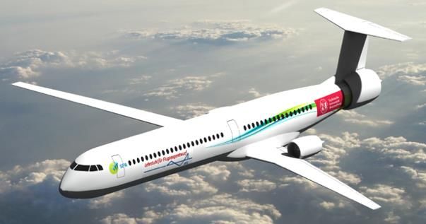
Deutscher Luft- und Raumfahrtkongress 2020
These four layers are connected to exchange information,
which can be used for multi-fidelity design optimization.
FIGURE 2. The multi-layer structure of ADEMAO. The last row shows the tools being used in each layer.
2.3. Preliminary results
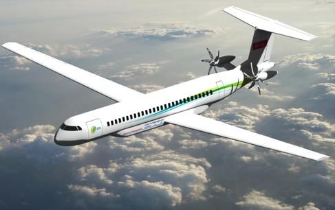
As the short-range reference aircraft, a full-electric aircraft
was designed based on the top-level requirements of the
ATR-72 (class) aircraft. Three different designs were ini-
tially developed and after the initial sensitivity study, the
best design was selected, see FIGURE 3. A comparison
between the SE2A short-range and the ATR-72 character-
istics is presented in TAB 1.
The same approach is used to design the mid-range refer-
ence aircraft. The top-level requirements are defined based
on Airbus A320 (class) aircraft. The final goal is to design a
hybrid-electric aircraft for this class, however in the first step
only gas-turbine propulsion by an ultra-high bypass ratio
turbofan is used. In the next step, electric propulsion will be
added to this design. For the mid-range aircraft, boundary
layer ingestion technology is used, by placing two engines
on top of the wings. Two different configurations were de- FIGURE 3. Three initial configurations for the SE2A
veloped, a forward swept wing and a backward swept wing. short-range aircraft (top) and the final design (bot-
The main reason for using the forward swept wing is the tom)
need for a low leading-edge sweep to maximize laminar
flow over the wing with minimum boundary layer suction. It
can be shown that for the same mid-chord sweep (or quar- Parameter SE2A-SR ATR 72 Change
ter-chord) a forward swept wing has a lower leading-edge (%)
sweep angle compared to a backward swept wing. The ini- MTOW (kg) 45942 23000 99.7
tial assessment of the two configurations showed that the OWE (kg) 36479 13311 174.0
aircraft with forward swept wing has superior performance L/Dmax 33.0 17.14 92.5
due to its larger extent of laminar boundary layers at the Cruise average 32.5 16.0 103.1
fuselage. The two configurations and the selected one are L/D
shown in FIGURE 4. TAB 2 summarizes the comparisons Block fuel (kg) 0 1377 -
between the characteristics of the SE2A mid-range aircraft Fuel efficiency 0 2.07 -
and the Airbus A320. (kg/seat/100 km)
TAB 1. Comparison between SE2A short-range
and ATR-72.
©2021 3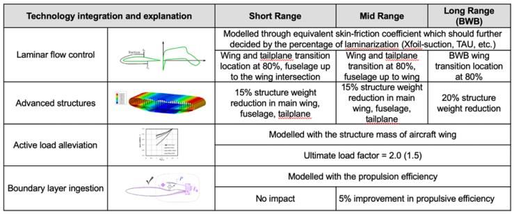
Deutscher Luft- und Raumfahrtkongress 2020

                                                                     drag does not only affects the flight performance of com-
                                                                     mercial aircraft; it will assume a much stronger contribution
                                                                     to direct operation costs in the future, due to the structural
                                                                     changes in energy supply economics. Therefore, the re-
                                                                     search strategy of the SE2A Cluster views drag reduction of
                                                                     commercial aircraft as a major enabler for sustainable avi-
                                                                     ation.
                                                                     3.1.   Drag Reduction Potentials and Challenges
                                                                     Technologies for drag reduction have always been on the
                                                                     research agenda. The aircraft drag comprises induced
                                                                     drag, wave drag, viscous drag, and miscellaneous, smaller
                                                                     parts. The potentials of technologies for reducing the lift de-
                                                                     pendant induced drag are rather limited as long as viscous
                                                                     drag dominates the overall drag balance. A similar state-
                                                                     ment holds for the wave drag of cruise flight at high Mach
                                                                     numbers. It is also known that passive and active means for
                                                                     reducing the friction drag of turbulent boundary layers are
                                                                     rather limited in their effect.
                                                                     Systematic laminarization of the major aircraft components
                                                                     offers the largest potential for reducing aircraft drag and
                                                                     hence reducing energy consumption. It also offers large in-
                                                                     direct gains by exploiting synergy effects on overall aircraft
                                                                     design level. This is demonstrated by recent preliminary de-
                                                                     sign computations of Beck et al. [4], who assessed bound-
                                                                     ary layer suction rates and the component drag of wing, tail
                                                                     and fuselage for a mid-range commercial aircraft. FIGURE
                                                                     8 shows drastic drag reduction potentials if comprehensive
                                                                     laminarization of all major aircraft components is intro-
                                                                     duced. Significant is also the so-called snowball effect on
                                                                     overall aircraft with respect to re-designing the wing plan-
                                                                     form and re-sizing the overall aircraft.

                                                                      FIGURE 8.      Viscous drag reduction by laminarization
                                                                         and effect on overall aircraft drag according to [4]
                                                                     Comprehensive laminarization goes far beyond designing
                                                                     the aircraft geometry for maximum natural laminar flow
                                                                     (NLF). NLF can only reduce the viscous drag of the wing
                                                                     and the tail, by about 40-50%. Further drag reductions are
                                                                     accessible only with active flow control by boundary layer
                                                                     suction (BLS). We note that BLS should be applied only
                                                                     where absolutely needed, as the required installation of
 FIGURE 7.      Influence of laminarization and load alle-           suction devices increases aircraft complexity, and adds to
    viation on battery weight, empty weight, and MTOW                the required suction power on board. This constitutes the
    of the SE2A short-range aircraft.                                so-called hybrid laminar boundary layer control (HLFC).
                                                                     BLS would typically be installed between 60 and 80 percent
3. AIRCRAFT DRAG REDUCTION                                           of the wing chord in order to yield the ultimate laminar wing.
The general research hypothesis of the SE2A Cluster re-              The general approach towards HLFC is not new. A number
garding aircraft design states that the expected changes in          of HLFC variants have been researched for several dec-
energy economics will cause step changes in the design               ades, and a significant number of successful tests in wind
requirements and operation of future viable aircraft. Aircraft       tunnel and in flight have been reported. Well known prob-
                                                                     lem areas are high manufacturing costs of wings with HLFC

©2021                                                            5
Deutscher Luft- und Raumfahrtkongress 2020
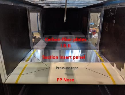
design task, the design approach follows a multiscale path bead profile affects the resulting layer orientation in this re-
with parametrized representations of the overall wing struc- gion, and automated fibre placement (AFP) is also an issue.
ture (coarse grain) and the integrated suction panel (fine
grain). As changes of the wing loads, the suction panel di-
mensions and the interior suction flow design must be taken
into account when new knowledge and new design meth-
odologies become available, the SE2A Cluster seeks auto-
mated processes in structural design with standardized in-
terfaces to exchange aerodynamic and structural design
data updates.
The passive structural solutions for load reduction dis-
cussed in Chapter 4 are not taken into account at this point,
since the combination of advanced HLFC and passive load
reduction is extremely challenging, and should be investi-
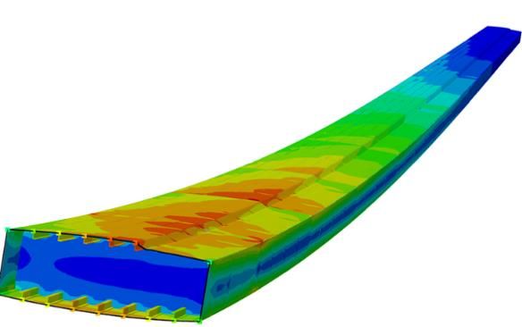
FIGURE 16. v. Mises stress distribution of the SE2A
gated only when mature solutions are available. Some
short-range reference aircraft wing box
practical aspects, as e.g. lightning strike protection, details
of flight control systems etc. are also not detailed during the Due to the fact that the cover plate of the suction panels
present fundamental research works. must be prevented from buckling (under compression and
shear), these parts of the suction panels must be widely
3.3.2. Overall Wing Structure load free. This means that the underlying wing skin struc-
The main part of the load carrying structure, i.e. the wing ture must carry the bulk load, and further measures have to
box, is assumed to be made of CFRP, by which the ad- be taken to unload the suction panel skin. This may be
vantage of CFRP thin-ply material with respect to weight achieved by separating the individual suction panels with-
reduction is accessible, see Section 3.3.4. The basic struc- out creating unwanted surface disturbances. One of the re-
tural design is assumed conventional, using flat shear webs search questions addresses the use of the lower skin of the
in spars and ribs, as well as straight stringers. The distinc- suction panel (at least) to act as stiffening members against
tion from conventional wing design is the beaded area buckling of the wing skin. Connected with this is the ques-
where the suction panels are to be integrated. FIGURE 15 tion of how to achieve a detachable joining of the suction
shows a sketch of a wing box section with only one symbolic panel with the wing skin, which is needed for maintenance.
suction panel shown. Elements like stringers and ribs are Whether additional stringers are needed in the region of this
just indicated without taking pitches, shapes and sizes as joint remains to be determined.
fixed. Also the position of the aft spar and possibly further
A further concern is the fluidic connection of the suction
spars in relation to the suction panel runout is the result of panel with the pump system. Depending on the necessities
parametrized input. from the aerodynamic design it could be advisable to locate
the required throttle holes in part of the forward bead and in
the load carrying wing box skin. This would mean that the
highly loaded areas have to be significantly severed, while
accessibility may be hampered by the adjacent stiffeners
mentioned above. Hence, the fluidic connections will have
a significant impact on the local stresses. Due to these dis-
turbances, fatigue will play an important role. Obviously,
multidisciplinary trade-offs are needed to balance aerody-
namic efficiency and structural weight penalties.
3.3.3. Thin Ply Material
The positive effect of using thin plies on static and fatigue
parameters, and on impact resistance is known since be-
ginning of this century. A comprehensive review has re-
FIGURE 15. Sketch of wing box section with suction cently been provided by Arteiro et al. [13]. Some features
panel of thin plies have already been found in the ‘70s, see e.g.
First design computations that take into account bending Parvizi et al. [14], and interpreted by Leguillon [15].
and torsion, reveal particular features of the overall wing The SE2A Cluster carries out a broad test program on the
structure: behaviour of CFRP thin ply laminates, including plane ten-
The forward bead initiates disturbances, both in the stress sion and compression, open-hole tension and compression
distribution as well as out-of-plane displacements, accord- and compression after impact (CAI). As an example, com-
ing to FIGURE 16. Depending on the suction panel concept parison of tension failure of quasi-isotropic thin ply material
this area may also comprise highly loaded joints. Hence, with 0.03 and 0.048 mm layer thickness with comparable
the adjacent stringer or spar needs additional stiffness, pos- material of 0.3 and 0.19 mm showed increased strength of
sibly an adapted directional stiffness, for complying with 27% and 36%, respectively. On the other hand, thin ply
aerodynamic geometry requirements. The impact is not open-hole tension specimens yielded a decrease in
only expected at the global level, but also detrimental strength. Small decreases were also found under compres-
stresses will occur at the laminar level, possibly resulting in sion and open-hole compression. However, these effects
inter-fibre failure or delamination. Here, careful shape de- depend on the specific material and on the particular lay-
sign of the bead profile will be essential. In addition, the up, as suited numbers of alternating fibre orientation angles
may improve performance.
©2021 9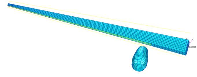
Deutscher Luft- und Raumfahrtkongress 2020

twisting, but also reduce the nonlinearity, and are therefore          ing low-order models of the system components for integra-
not beneficial for the proposed load alleviation technique.            tion in the overall model, and finally assessing the control
                                                                       technologies. The assessment of the full system, including
These results show that a wing box with a nonlinear behav-             load alleviation functions, also provides valuable insight as
iour that contributes to load alleviation can be designed.             to whether the initial requirements were correct, or whether
The real load-alleviation capabilities will be evaluated in the        they should be adjusted. For instance, the tuning of the load
second and third project phases with detailed fluid structure          alleviation functions for best overall performance could fa-
interaction simulations.                                               vour significantly lower actuation speeds as initially speci-
                                                                       fied. This would allow for relaxing the initial specification,
                                                                       and hence, avoid unnecessarily heavy subsystems.
                                                                       The design of the load alleviation functions is therefore a
                                                                       task that must be repeatedly performed, as a range of com-
                                                                       binations of sensors and actuators will be considered, be-
                                                                       cause several design loops may be required for each com-
                                                                       bination, and because the overall aircraft design itself,
                                                                       through evolution of the assumed technologies, will also
                                                                       evolve over time. As the mid-range reference aircraft is the
                                                                       initial focus of load alleviation, the research project on ac-
                                                                       tive load control systems plays an important role in the over-
 FIGURE 22.    Deformation of a wing-box with nonlinear                all design of this reference configuration of the SE2A Clus-
    upper skin and rear spar behavior                                  ter.
                                                                       The techniques and methodologies used for the design of
                                                                       the active load alleviation functions represent a major part
                                                                       of the research work. This Cluster research comprises two
                                                                       main approaches in this respect: an adaptive control ap-
                                                                       proach and a robust control approach.
                                                                       The behaviour of the flexible aircraft depends on the precise
                                                                       mass distribution of the payload, the amount of fuel in the
                                                                       wings, and even on slight differences between individual
                                                                       aircraft, among many other parameters. The robust control
                                                                       approach considers only parameters that can be reliably
                                                                       known, measured, or estimated as scheduling variables.
                                                                       These typically include a small set of characteristics of the
                                                                       actual operating point such as Mach number, dynamic pres-
                                                                       sure, and mass. All other effects are uncertainties against
                                                                       which the load alleviation functions must be robust. Conse-
                                                                       quently, it is expected that the robust control approach,
                                                                       compared to the adaptive approach, will provide controllers
 FIGURE 23.     Load displacement curve for the rotation               that sacrifice some performance in favour of robustness
    of the wing-box in FIGURE 22                                       and easier certification. The difference in load alleviation
                                                                       performance between these two approaches will hence be
4.2.    Active Load Alleviation                                        investigated: depending on how large this difference is, the
The SE2A Cluster promotes fundamental research in active               additional complexity of the adaptive approach (especially
load control techniques that include the synthesis of control          for certification) might be justified or not. Prior work on both
systems and the definition of sensor and actuation subsys-             approaches can be found in Refs. [29], [30] and references
tems.                                                                  therein.

The approach integrates the components and technologies                The Cluster research also addresses questions related to
developed in other Cluster projects into a single model of             innovative sensor configurations. For instance, by fusing
fairly low order which comprises several hundred to a few              measurements from sensors distributed throughout the air-
thousand states. Depending on the various combinations of              frame, the current state of the airplane, including its flexible
technologies selected (e.g. on the sensors and actuators),             modes, can be better estimated. Another promising sensor
various models will be created. These models include the               technology is the use of a Doppler lidar sensor to de-
structure, the aerodynamics (including unsteady effects),              tect/measure the gust a short distance ahead of the aircraft
and the actuation and sensor systems, as well as a simula-             (typically 50-150 m). As demonstrated in previous investi-
tion of the flight control computers with various functions,           gations (see e.g. [31]), a short anticipation time of about
such as basic flight control laws, autopilot modes, and ac-            0.2-0.3 s already permits significant improvement of the
tive load alleviation.                                                 gust load alleviation performance by e.g. enabling the use
                                                                       of small pitch manoeuvres to partly compensate the gust-
The design of active load alleviation functions for the differ-        induced angle of attack variations. The definition of precise
ent combinations of sensors and actuators is one of the                lidar sensor requirements is expected to be a challenging
main tasks of this research project. This task also involves           task. This investigation will likely be performed in a similar
many interactions with the groups designing the system                 manner as the work presented in [32] for the detection and
components, starting from specifying the needs and re-                 alleviation of wake vortices.
quirements for the load alleviation functions, then develop-

©2021                                                             13
Deutscher Luft- und Raumfahrtkongress 2020
References [18] Krishnan, K.S.G; Bertram, O; Seibel, O.: Review of hy-
brid laminar flow control systems. Progress in Aero-
[1] Budziszewski, N., and Friedrichs, J. , Modelling of A space Sciences 93 (2017), S. 24–52.
Boundary Layer Ingesting Propulsor, Ener- [19] Schneider, M; Horn, M; Ritt, S; Seitz, A.: Structural de-
gies 11(4):708, 2018 sign and testing of a Tailored Skin Single Duct (TSSD)
[2] Schefer, H., L. Fauth, T. H. Kopp, R. Mallwitz, J. Friebe fin application: ICAS 2018.
and M. Kurrat, "Discussion on Electric Power Supply [20] Seitz, A.: HLFC for Transonic Transport Aircraft. Some
Systems for All Electric Aircraft," in IEEE Access, vol. Aspects of Aerodynamic Design and Flow Engineer-
8, pp. 84188-84216, 2020, doi: ing.
10.1109/ACCESS.2020.2991804. [21] Abueidda, D; Elhebeary, M; Shiang, C.-S; Pang, S;
[3] Liu, Y., Elham, A., Horst, P., Hepperle, M., Exploring Abu Al-Rub, R; Jasiuk, I.: Mechanical properties of 3D
Vehicle Level Benefits of Revolutionary Technology printed polymeric Gyroid cellular structures: Experi-
Progress via Aircraft Design and Optimization, Ener- mental and finite element study. Materials & Design
gies, 2018, 11(1), 166; doi:10.3390/en11010166. 165 (2019), p. 107597.
[4] Beck, N., Landa, T., Seitz, A., Boermans, L., Liu, Y., [22] FAA, Statistical Loads Data for the Airbus A-320 Air-
Radespiel, R., Drag Reduction by Laminar Flow Con- craft in Commercial Operations, Report DOT/FAA/AR-
trol, Energies, vol. 11, no. 1, p. 252, 2018. 02/35, Springfield, Virginia, 2002.
[5] Bronkhorst, A.: Pressure Loss Measurements and [23] FAA, Statistical Loads Data for the Boeing 777-200ER
structural Analysis for the prediction of a Sailplane Aircraft in Commercial Operations, Report
Wing Section with Boundary Layer Suction. Master DOT/FAA/AR-06/11, Springfield, Virginia, 2006.
Thesis, Delft, 2008. [24] Brojan, M., Cebron, M., Kosel, F., Large deflections of
[6] van Ingen, J.L., 50 years e^N. Historical Review 1956- non-prismatic nonlinearly elastic cantilever beams sub-
2006 of Work at Delft Aerospace Low Speed Labora- jected to non-uniform continuous load and a concen-
tory including a New Version of the Method, trated load at the free end, Acta Mech. Sin. (2012)
2006,https://surfdrive.surf.nl/files/in- 28(3):863–869 DOI 10.1007/s10409-012-0053-3.
dex.php/s/JNqoleDxl1ZREMP. [25] Gröhlich, M. Böswald, M. and Winter, R. . An iterative
[7] Bongers, J. Implementation of a new Transition Predic- eigenvalue solver for systems with frequency depend-
tion Method in XFOIL. Master Thesis; Delft 848 Univer- ent material properties. In Proceedings of the DAGA
sity of Technology, Delft, 2006. 2020, Hannover, Germany, 2020.
[8] Hanifi, A., Pralits, J., Amoignon, O., Chevalier, M.: [26] Gröhlich, M., Böswald, M., and Winter, R. . Vibration
Laminar flow control and aerodynamic shape optimiza- damping capabilities of treatments with frequency de-
tion. Proc. KATnet II Conference on Key Aerodynamic pendent material properties. In Proceedings of the ICA
Technologies, 12-14 May 2009, Bremen, Germany. 2019, Aachen, Germany, 2020.
ISBN 978-3-00-027782-5. [27] Dähne, S., Hühne, C. , 2018. Gradient Based Struc-
[9] Hein, S., Bertolotti, F.P., Simen, M., Hanifi, A., Hen- tural Optimization of a Stringer Stiffened Composite
ningson, D.: Linear nonlocal instability analysis — the Wing Box with Variable Stringer Orientation. Advances
linear NOLOT code —. DLR Internal Report, DLR-IB in Structural and Multidisciplinary Optimization.
223-94 A56, 1995. https://doi.org/10.1007/978-3-319-67988-4_62.
[10] Herbert, T.: On the stability of 3D boundary layers. 28th [28] Wunderlich, T.F., Dähne, S., Reimer, L., Schuster, A.,
AIAA Fluid Dynamics Conference, 4th AIAA Shear Brodersen, O., 2020. Global Aero-Structural Design
Flow Control Conference, June 29 - July 2, 1997, Optimization of More Flexible Wings for Commercial
Snowmass Village, Colorado. AIAA 97-1961. Aircraft, in: AIAA AVIATION 2020 FORUM, AIAA
[11] TAU-Code User Guide - Release 2019.1.2. February AVIATION Forum. American Institute of Aeronautics
25, 2020. and Astronautics. https://doi.org/10.2514/6.2020-
[12] Giesecke, D., and Friedrichs, J.: Aerodynamics and 3170.
loss accounting of a low pressure ratio fan for an over- [29] Beyer, Y., Kuzolap, A., Steen, M., Diekmann, J.-H.
wing mounted engine, in: Radespiel, R. and Semaan, and Fezans, N. : “Adaptive Nonlinear Flight Control of
R. (eds.), Fundamentals of High Lift for Future Civil Air- STOL-Aircraft Based on Incremental Nonlinear Dy-
craft, NNFM, Vol. 146, 2000. namic Inversion”, Proceedings of the 2018 AIAA Avia-
[13] Arteiro, A., Furtado, C., Catalanotti, G., Linde, P., & Ca- tion Forum, Atlanta, GA, USA. AIAA 2018-3257. DOI:
manho, P. P. (2020). Thin-ply polymer composite ma- 10.2514/6.2018-3257.
terials: A review. Composites Part A: Applied Science [30] Khalil, A., and Fezans, N. : “A Multi-Channel H∞ Pre-
and Manufacturing, 132, 105777. view Control Approach to Load Alleviation Function
[14] Parvizi, A., Garrett, K. W., & Bailey, J. E. (1978). Con- Design”, Proceedings of the 2019 CEAS Conference
strained cracking in glass fibre-reinforced epoxy cross- on Guidance, Navigation and Control, Milano, Italy.
ply laminates. Journal of Materials Science, 13(1), 195- [31] Fezans, N., Joos, H.-D., Deiler, C. : “Gust Load Alle-
201. viation for a Long-Range Aircraft with and without An-
[15] Leguillon, D. (2002). Strength or toughness? A criterion ticipation”, CEAS Aeronautical Journal, 10(4), 1033-
for crack onset at a notch. European Journal of Me- 1057, Dec. 2019. DOI: 10.1007/s13272-019-00362-9.
chanics-A/Solids, 21(1), 61-72. [32] Ehlers, J. and Fezans, N. : “Airborne Doppler LiDAR
[16] Hannig, A. (2018). Static and fatigue transverse crack Sensor Parameter Analysis for Wake Vortex Impact Al-
initiation in thin-ply fibre-reinforced composites. Doc- leviation Purposes”, Proceedings of the 2015 CEAS
toral Thesis, TU Braunschweig, NFL- Conference on Guidance, Navigation and Control,
Forschungsbericht 2018-2, ISBN 978-3-928628-97-6 Toulouse, France.
[17] Fernandez, A; Ückert, C.: Joining Concept Selected [33] Khalil, K., Asaro, S. , and Bauknecht, A. , “Active Flow
Deliverable D1.4.1.2 6 Project Echo. Control Devices for Wing Load Alleviation,” in AIAA
Aviation 2020 Forum, 2020, pp. 1–22.
©2021 15Deutscher Luft- und Raumfahrtkongress 2020
[34] Düssler, S., “Design and Experimental Investigation of
a Coanda-Type Flow Actuator for Lift Reduction on a
2D Airfoil,” Master thesis, Institute of Fluid Mechanics,
Technical University Braunschweig, Germany, 2020.
©2021 16You can also read