ELEMATIC Hollow-core Plank
←
→
Page content transcription
If your browser does not render page correctly, please read the page content below
ELEMATIC®
Hollow-core
Plank

2014 Technical Data Guide for Precast,
Prestressed Concrete Hollow-core Plank
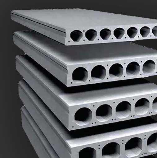

Table of Contents
Introduction.................................. 1
Manufacturing Process..................... 1
Delivery & Installation...................... 1
Load Table Design Criteria.............. 1 - 2
Plank Design Considerations............... 2
Fire Ratings.............................. 2 - 3
Thermal “R” Values......................... 3
Sound Ratings........................... 3 - 4
Sustainability................................ 4
Specifications.......................... 5 - 8
Tolerances. . . . . . . . . . . . . . . . . . . . . . . . . . . . . . . . . . 9
Load Tables.......................... 11 - 20
Details................................ 21 - 33
Introduction Delivery & Installation
The purpose of this product manual is to provide assistance in select- Oldcastle hollow-core plants are located in Selkirk, NY (near Albany,
ing and detailing precast concrete hollow-core plank manufactured by NY) and in Edgewood, MD (near Baltimore, MD). Our precast hollow-
Oldcastle Precast, Inc. core planks are shipped by truck/trailer to the crane on site (generally
The load tables presented herein are intended as a guide only. Final less 300 miles from our plants) Oldcastle’s project team will coordinate
design is determined by our engineering department based on informa- overall schedule, erection sequence, safety plans, and other project
tion presented in the final plans and specifications. Loading information parameters with each customer to ensure on-time delivery.
including SDL, LL, snow drift, and non-uniform concentrated & line loads
more than 1.0 kip or 0.100 klf should be stated by the project structural Our project scope can include installation and grouting by Oldcastle’s
engineer of record (SER). Lateral loading requirements from wind and experienced and PCI certified field crews; or FOB delivery only for
seismic analysis can be specified in the form of including our standard installation by the general contractor and his/her erector. The erector will
connection details, or by stating floor diaphragm shear forces in klf on the install the precast planks in accordance with PCI tolerances which include
structural plans. For additional design assistance, please contact us at occasional cutting and trimming of the concrete to adjust for product and
800-523-3747 and ask for our engineering dept. field tolerances, and interference with steel connections not shown on
Although care has been taken to provide the most accurate data pos- contract & shop drawings. However, it is the responsibility of the project
sible, Oldcastle Precast, Inc. does not assume responsibility for design team and general contractor to provide information to Oldcastle
errors and omissions. Precast to have as many factory cuts and notches as possible. Grouting
material consists of 1:3 cement-sand grout with a minimum 28-day
Manufacturing Process strength of 2,500 psi placed in all plank joints, and sometimes also at
perimeter joints. Higher grout strengths of 4,000 psi is used on CFS
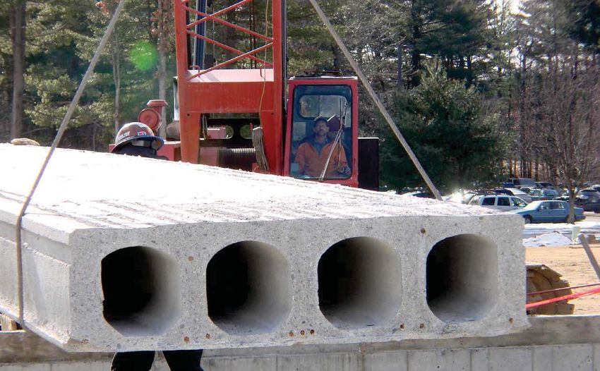
Elematic® is a machine extruded, precast, prestressed hollow-core
load bearing metal stud and Girder-Slab shallow steel beam structures.
plank. The planks are manufactured on 500-foot-long steel beds in
standard widths of 48 inches and thickness of: 8, 10, 12 and 16 Field grout is delivered by ready mix truck and placed by crane bucket
inches. High strength prestressing strands are cast into the planks at the and grout brooms, or by grout pump. Pre-packaged non-shrink grout is
spacing and location required for the given span, loading and fire cover not used in hollow-core plank grouting.
conditions. Oldcastle plants are capable of extruding up to 12,000 SF of
precast plank every day to meet project schedules. The planks are cut to Load Table Design Criteria
length for each project using a diamond-blade saw. After the planks are
cut, they are removed from the casting beds and placed into storage, and The tables herein list allowable live loads in pounds per square foot
ready for shipment. (PSF) for uniformly distributed loading. Non-uniform loading conditions
resulting from point loads, line loads, openings and cantilevers require
All Elematic materials equal or exceed the requirements of applicable
special design consideration. The SER should specify the required
ASTM specifications. Our concrete mix is designed to have release
strengths of 3,000 psi or 3,500 psi, and a 28-day compressive strength uniform and special loading on the structural drawings. Oldcastle
of 5,000 psi. For sustainability, our concrete mix has been fined tuned to engineering will perform all engineering analysis and submit PE stamped
use less cement to lower our carbon footprint, but fly ash is not added. calculations to the GC/Architect/SER for review and approval prior to
fabrication.
The prestressing strands are uncoated, seven wire, low relaxation with
a minimum ultimate strength of 270 ksi. Load Table values are calculated in accordance with ACI 318-11
Our manufacturing capabilities also include: longitudinal and skew cuts design standard and comply with L/360 deflection limits.
to fit any building shape, adding top strands for cantilever designs, cast-in Load tables are based on a plank concrete strength of 5,000 psi.
bottom 6”x4” embed plates for welded connections to steel structures, Tables for topped sections are based on a topping strength of 3,500 psi
cast-in top plates for curtain wall and relieving angle attachments, column and minimum thickness of 2 inches
notches, side grout pockets for rebar connections to shear walls, top
slots for field grouting of hollow-cores needed for rebar connections and Plank self-weight and 2” concrete composite topping are both
additional shear capacity, and plant cast weep holes. included, and do not need to be added to your design loads to compare
to these load tables.
Be sure to discuss your project scope with your Oldcastle sales
representative in detail as each project should decide which details are See “Notes” section in the load tables for other helpful design tips on
required for design and constructability. using our load tables. It is possible to exceed the values in these load
www.oldcastlesystems.com Elematic® Hollow-core Plank Technical Guide 1tables by approximately 10% if the area in question is adjacent to side Camber
wall or beam support, or shorter spans. • Camber is inherent in all prestressed products. It is the result of the
For initial design, the following span to depth ratios (L/D) can be used eccentric prestress force required to resist design loads, and cannot
to determine maximum spans and hollow-core plank thickness: be designed in, out, or to an exact number. The amount of camber
will depend upon the design loads, span and thickness of plank.
Maximum Span to Depth Ratio Planks stored in the yard for more than 4 weeks, usually due to
construction schedule changes, will experience more camber growth.
Residential Loading of 20 SDL + 40 LL 48 • Adjacent plank of dissimilar length or dissimilar strand pattern will
Residential Loading with masonry partitions 35 have inherent camber differences.
• Camber can be approximated as 0.3% of the span and must be
Common/Assembly Loading of 10 SDL + 100 LL 42 taken into account when specifying concrete topping thickness. For
example, if 2-1/2” concrete topping thickness is specified, a mini-
mum topping thickness of 1-1/2” is still achieved with a maximum
Plank Design Considerations plank camber of 1” at mid-span.
• The approximate short term camber loss from 30 psf live load is
The following items will affect the selection of appropriate plank sizes
1/4”. This value can be used as a guide for curtain wall connection
and should be carefully reviewed by the Architect/Engineer (SER = struc-
design to the perimeter edge of the precast plank. The precast plank
tural engineer of record) while developing the plans and specifications for
will revert back to full camber once the live load is gone.
a project:
• The approximate long term camber loss from material shrinkage &
Loading Conditions creep is 1/8” in 5 years and 1/4” in 20 years.
• Specify all uniform loading requirements on structural drawings.
• Specify snow drift loads per ASCE-7 on the roof plan. Fire Rating
• The SER should specify plank connection details and/or diaphragm Fire rating specifications are as important as all other design param-
shear forces resulting from wind and seismic lateral analysis; and eters. Plank rating requirements are determined by the Architect or
retained earth if present. Structural Engineer of Record (SER), who is also responsible for estab-
• Identify line and point loads resulting from masonry partition walls, lishing the fire rating criteria for the total project.
face brick, posts, mansards, RTUs, mechanical equipment, etc. Four methods generally used for determining precast hollow core plank
• In general, the plank floor system can be designed for MEP openings fire-resistant ratings are:
and small skylights less than 4’-0” wide.
1. 2012 ICC International Building Code
• Larger openings such as elevator shafts, stair shafts, and MEP shafts 2. Underwriters Laboratories Fire Resistance Ratings
larger than 4’-0” wide will require additional structural support for the
3. NYC OTCR approved product & manufacturer certification (New York
precast planks.
City only)
Topping 4. Rational analysis as defined by PCI MNL 124, “Design for Fire
• Specify whether or not concrete topping is to be composite. Com- Resistance of Precast Concrete”
posite action requires the topping to be bonded to the top surface of International Building Code “IBC” Fire Ratings
the plank. Oldcastle Precast’s standard is to provide a longitudinal
The ICC-IBC code prescribes fire ratings to any precast hollow-core
machine drag rake finish on the top of the precast planks to provide
plank section. Since 2000, the ICC-IBC code has replaced the BOCA,
an intentionally roughened finish for improved bonding with the
SBC and UBC model codes in all 50 states. The two criteria that are
composite topping.
measured to determine the fire rating are:
• “Topped” load tables are calculated with a maximum horizontal shear
1. Equivalent concrete thickness – 4.6” is required for 2 hrs
stress of 80 psi between the top of the precast plank and the bottom
of the topping. 2. Bottom strand cover – ¾” cover is required for 2 hrs (restrained
condition)
• Topping separated by a vapor barrier or insulation is non-composite
and must be considered a superimposed dead load. Underwriters Laboratories Fire Resistance Ratings
• Large cambers resulting from heavy loads will affect the quantity of Prior to codes including prescriptive fire-endurance rating methods, fire
topping, assuming a level floor is required. 1-1/2” of composite tests provided the primary source of ratings classifications. While some
topping at mid span is minimal, and additional thickness at the ends plank sections were fire tested, others can be evaluated by UL from
of the plank may be required to maintain level floor elevations. similar existing UL ratings.
2 Elematic® Hollow-core Plank Technical Guide www.oldcastlesystems.comThe table below lists the UL ratings available with Elematic plank. Note Thermal “R” Values
that these ratings are dependent upon whether or not the ends of the Concrete is a dense material, and as a result, is not a good insulating
planks are restrained. Determination of the restraint must be made by material. On occasion, a designer who needs the thermal “R” value of
the Architect or the Structural Engineer of Record (SER), as it is primarily precast concrete hollow-core planks, can reference the table below.
a function of the support structure. Although there is some improvement for filling the plank hollow-cores
with foam insulation, the losses from thermal bridging of the concrete
Rating (Hour) Plank Topping
UL webs greatly reduces the effectiveness of the added insulation. There is
Thickness Thickness
Number also a cost premium and longer lead time associated with adding foam
Restrained Unrestrained (inch) (inch)
insulation. A much more economical design option is to specify 1’-3”
J994 1½ 11∕2 8,10,12 0 of batt insulation (widely available in 15” rolls) installed into the cores at
areas of high potential heat loss, in the field by the general contractor.
J994 2 11∕2 8,10,12 1
∕2 Gypcrete
Thermal “R” Values
J994 3 11∕2 8,10,12 21∕8 Topping
J994 4 11∕2 8,10,12 33∕8 Topping 8” Elematic® 1.34
J995 2 2 8,10,12 0 8” Elematic® with foam insulation in cores 3.14
J995 3 2 8,10,12 11∕2 Topping H8” Heavy Elematic ® 1.43
J995 4 2 8,10,12 25∕8 Topping H8” Heavy Elematic® with foam insulation in cores 2.72
H10” Heavy Elematic® 1.73
New York City OTCR Product Approval
H10” Heavy Elematic® with foam insulation in cores 4.05
For projects within New York City, the NYC Dept. of Building requires
the precast hollow-core manufacturing plant to be pre-approved by the 12” Elematic® 1.91
Office of Technical Certification & Research (OTCR). Historically, this
12” Elematic® with foam insulation in cores 5.01
certification was known as the MEA certification (Material & Equipment
Acceptance) prior to the 2008 NYC Building Code. Oldcastle Precast 16” Elematic® 2.28
has been a NYC approved precast hollow-core plank manufacturer since
16” Elematic® with foam insulation in cores 7.48
the early 1970s.
2” concrete topping +0.15
Fire Ratings by Rational Analysis
3” concrete topping +0.23
PCI MNL 124 defines the “rational analysis” method for determining
the fire resistance rating of precast/ prestressed members. It is useful to 2” lightweight concrete roof topping (110 pcf) +0.35
use when a fire resistance rating cannot be obtained by any of the three
4” lightweight concrete roof topping (110 pcf) +0.70
previous methods. Actual practice has shown that this method is very
conservative and that the span of the hollow-core plank will have to be 6” lightweight concrete roof topping (110 pcf) +1.05
reduced (approx. 10% to 20%) to achieve the same fire resistance rating
from both IBC and UL. Sound Ratings
In using this method, the reduced strength of the prestressed strands The following tables contain values for the Sound Transmission Class
at elevated temperatures is determined and the resulting moment (STC) and the Impact Insulations Class (IIC) of various floor systems utiliz-
capacities are compared to that required for service loads. Strand ing Elematic precast hollow-core plank.
temperatures are based on the amount of concrete cover and the
Sound Transmission Class (STC)
standard fire exposure as defined by the time-temperature relationship
The values for the Sound Transmission Class were determined by test-
specified in ASTM E119. Fire ratings will also be improved if the plank ing in accordance with ASTM E90. The STC is a measure (in decibels) of
assembly is restrained against thermal expansion. It should be noted the ease at which air-borne sound is transmitted through a floor system.
that the only universally accepted definition of full restraint is an interior The density and mass of precast concrete planks is ideal for achieving
bay of a multi-bay building. larger STC values, which indicate greater sound insulation.
www.oldcastlesystems.com Elematic® Hollow-core Plank Technical Guide 3Sound Transmission Class (STC) Sustainability
It is recognized that the production of cement is a high contributor of
8” Elematic® 51
CO2 in industry. In 2013, a joint LCA study conducted by the Precast
8” Elematic® + 2” Topping 54 Concrete Institute (PCI), Canadian Prestressed Concrete Institute (CPCI),
H8” Heavy Elematic ® 51 and the National Precast Concrete Association (NPCA) confirmed this and
also gave our industry a benchmark for future improvements. The follow-
H8” Heavy Elematic® + 2” Topping 55 ing sustainable practices are already in place to manufacture, deliver and
H10” Heavy Elematic ® 53 install our Elematic® hollow-core planks:
• Use the lowest cement content in manufacturing while still achieving
H10” Heavy Elematic® + 2” Topping 56
consistent concrete strengths.
12” Elematic ® 54 • Although fly ash can be added to divert the fly ash waste from
12” Elematic® + 2” Topping 57 landfills, we cannot replace any more cement from our optimized
concrete mix.
16” Elematic ® 56
• Advance machine extrusion technology casts Elematic hollow-core
®
16” Elematic + 2” Topping 59 planks with 44%-52% less concrete compared to the equivalent
thickness solid concrete slab.
Impact Insulation Class (IIC) • Proven prestressing technology since the 1960s with ASTM
A416 steel strands with 270 ksi yield strength (4.5X stronger than
The values for the Impact Insulation Class (IIC) were determined by tests
conventional rebar) increases our maximum span by approx. 75%
which were in accordance with ASTM ES492. Impact Insulation Class is
more than continuous design CIP solid concrete slabs of the same
the resistance to impact noise transmission and is mostly influenced by
thickness which results in less framing elements such as columns,
the finish material applied on top of the precast planks. A soft material
beams, and bearing walls.
such as carpeting will achieve the best IIC ratings. As with STC, the high-
er IIC values are more desirable. Note that IIC testing is typically done • Steel casting beds provide the most consistent smooth bottom finish
without any other additional forming waste (ie. no wood).
by the finish material manufacturer on 6” solid concrete slabs. These
test values can be used on other slab thickness and precast hollow-core • Both radiant heating in our casting beds and natural curing are used
planks since the effect of the mass of the underlying slab is negligible for depending on the season to achieve proper curing with the lowest
impact noise absorption. energy use. Steam curing is not used.
• All our concrete constituent materials including cement, limestone
Impact Insulation Class (IIC) aggregates, and sand; are extracted from nearby sources well within
Types of Floor Systems Rating the 500 miles LEED criteria.
• All water is pumped from on site wells, reducing the demand on the
8” Hollow-core Plank 28
local municipal water supply.
1
8” Hollow-core Plank + ∕2” wood block flooring • Waste precast hollow-core plank in our yard is crushed and sepa-
47
adhered directly
rated in our yard. The crushed concrete is used for clean fill material
8” Hollow-core Plank + VCT, (ex. Armstrong) 47 -56 by local road contractors and land owners. All scrap steel is delivered
to recycling centers.
8” Hollow-core Plank + quarry tile w/reinforced
mortar bed with 0.4” nylon & carbon black 54 • On the job site, multiple planks can sometimes be picked to reduce
spinneret matting the overall erection time to shorten the overall construction schedule
8” Hollow-core Plank + pad & carpet 73 and minimize noise pollution. Up to 10,000 sf of Elematic® hollow-
core planks can be installed in a single day.
Add Acoustical Ceiling +6
Oldcastle Precast continues to search for more future sustainable
practices.
4 Elematic® Hollow-core Plank Technical Guide www.oldcastlesystems.comP
SPECIFICATIONS FOR PRECAST, PRESTRESSED HOLLOW-CORE PLANK
SECTION 03400
1. GENERAL
1.01 Description
A. Work Included:
1. These specifications cover manufacture, transportation and erection of precast, prestressed, concrete, hollow-core
plank, including grouting of joints between adjacent units.
B. Related Work Specified Elsewhere:
2. Cast-in-Place Concrete: Section_________
3. Architectural Precast Concrete: Section_________
4. Precast Structural Concrete: Section ________
5. Underlayments (Floor and/or Roof Leveling): Section________
6. Caulking and Sealants: Section _______
7. Small Holes for Mechanical/Plumbing: Section ______
8. Cast-in-Place Embedments: Section________
9. Steel Bearing Lintels: Section _________
10. Insulation in Plank Cores: Section ________
1.02 Quality Assurance
A. Manufacturer Qualifications: The precast concrete manufacturing plant shall be certified by the Prestressed Concrete
Institute (PCI) Plant Certification Program prior to the start of production. Manufacturer shall be certified in category C2.
The manufacturer shall retain a registered structural engineer to certify that manufacturing is in accordance with design
requirements; or
The manufacturer shall, at his expense, meet the following requirements:
1. The basis of inspection shall be the Prestressed Concrete Institute’s “Manual for Quality Control for Plants and Pro-
duction of Precast and Prestressed Concrete Products”, MNL-116, and the criteria for acceptance shall be the same
as the Plant Certification Program.
B. Erector Qualifications: PCI Qualified and regularly engaged for at least 5 years in the erection of precast structural
concrete similar to the requirements of this project. Retain aregistered structural engineer to certify that erection is in
accordance with designrequirements.
C. Welder Qualifications: In accordance with AWS D1.1.
D. Testing: In general compliance with applicable provisions of Prestressed Concrete Institute MNL-116, “Manual for Quality
Control for Plants and Production of Precast Prestressed Concrete Products”.
E. Requirements of Regulatory Agencies: All local codes plus the following specifications, standards and codes are a part of
these specifications:
1. ACI 318 – Building Code Requirements for Reinforced Concrete;
2. AWS D1.1 – Structural Welding Code-Steel;
3. AWS D1.4 – Structural Welding Code-Reinforcing Steel;
4. ASTM Specifications – As referred to in Part 2-Products, of this Specification.
www.oldcastlesystems.com Elematic® Hollow-core Plank Technical Guide 51.03 Submittals and Design
A. Shop Drawings:
1. Erection Drawings
Plans locating and defining all hollow-core planks furnished by the manufacturer, with all major openings
shown.
a. Sections and details showing connections, weld plates, edge conditions and support conditions of the hol-
lowcore plank units.
b. All dead, live and other applicable loads used in the design.
c. Fire rating.
B. Approvals:
1. Submit _______ copies of erection drawings for approval prior to fabrication. Fabrication not to proceed prior to
receipt of approved drawings.
C. Product Design Criteria:
1. Loadings for design
a. Initial handling and erection stresses.
b. All dead and live loads as specified on the contract documents.
c. All other loads specified for hollow-core plank where applicable.
2. Fire rating shall be _____ hour(s).
3. Design steel plank support headers when such headers are determined necessary by the manufacturer’s engineer.
4. Design calculations shall be performed by an engineer, registered in the state that the project is located in, and
experienced in precast prestressed concrete design. Design calculations to be submitted for approval upon request.
5. Design shall be in accordance with ACI 318 and applicable codes.
D. Permissible Design Deviations:
1. Design deviations will be permitted only after the Architect/Engineer’s written approval of the manufacturer’s pro-
posed design supported by complete design calculations and drawings.
2. Design deviations shall provide an installation equivalent to the basic intent without incurring additional cost to the
owner.
E. Test Reports: Test reports on concrete and other materials shall be submitted upon request.
2. PRODUCTS
2.01 Materials
A. Portland Cement:
1. ASTM C150 – Type I or III.
B. Admixtures:
1. Water Reducing, Retarding, Accelerating, High-Range Water Reducing Admixtures: ASTM C494
C. Aggregates:
1. ASTM C33 or C330
D. Water: Potable or free from foreign materials in amounts harmful to concrete and embedded steel.
E. Reinforcing Steel:
1. Bars:
Deformed Billet Steel: ASTM A615
Deformed Rail Steel: ASTM A616
Deformed Axle Steel: ASTM A617
Deformed Low Alloy Steel: ASTM A706
2. Wire: Cold Drawn Steel: ASTM A82.
F. Prestressing Strand:
1. Uncoated, 7-Wire, Low Lax strand: ASTM A416 (including supplement) – Grade 250K or 270K.
6 Elematic® Hollow-core Plank Technical Guide www.oldcastlesystems.comG. Welded Studs: In accordance with AWS D1.1.
H. Structural Steel Plates and Shapes: ASTM A36.
I. Grout:
1. Cement grout: Grout shall be a mixture of not less than one part portland cement to three parts fine sand, and the
consistency shall be such that joints can be completely filled but without seepage over adjacent surfaces. The grout
shall achieve a minimum 28-day compressive strength of 2,000 psi. Any grout that seeps from the joint shall be
completely removed before it hardens.
J. Bearings Strips:
1. Plastic: Multi-monomer plastic strips shall be non-leaching and support construction loads with no visible overall
expansion.
2.02 Concrete Mixes
A. 28-day compressive strength: Minimum of 5,000 psi
B. Release strength: Minimum of 3,000 psi
C. Use of calcium chloride or admixtures containing chlorides is not permitted.
2.03 Manufacture
A. Hollow-core plank shall be machine cast in 48-inch widths under the trade name Elematic® as manufactured by Old-
castle Precast Building Systems.
B. Manufacturing procedures and tolerances shall be in general compliance with PCI MNL 116.
C. Openings: Manufacturer shall provide for rectangular openings 10 inches or larger on all sides and as clearly shown on
the architectural and structural drawings. They shall be located by the trade requiring them and then field cut. Round and
small openings (less than 10 inches) shall be drilled or cut by the respective trades after grouting. Openings requiring cut-
ting of prestressing strand shall be approved by the precast plank manufacturer before drilling or cutting.
D. Finishes: Bottom surface shall be flat and uniform as resulting from an extrusion process, without major chips, spalls and
imperfections. Top surface shall be machine troweled.
E. Patching: Will be acceptable providing the structural adequacy of the hollow core unit is not impaired.
3. EXECUTION
3.01 Product Delivery, Storage and Handling
A. Delivery and Handling:
1. Hollow-core plank shall be lifted and supported during manufacturing, stockpiling, transporting and erection opera-
tions only at the lifting or supporting points designated by the manufacturer.
2. Transportation, site handling and erection shall be performed by qualified personnel with acceptable equipment and
methods.
B. Storage:
1. Store all units off ground on firm, level surfaces with dunnage placed at bearing points.
2. Place stored units so that identification marks are discernible.
3. Separate stacked units by dunnage across full width of each plank.
3.02 Erection
A. Site Access: Erection access suitable for cranes and trucks to move unassisted from public roads to all crane working
areas as required by erector, or otherwise indicated herein, will be provided and maintained by the general contractor.
Obstructing wires shall be shielded or removed and, when applicable, snow removal and winter heat will be provided by
the general contractor.
B. Preparation: The general contractor shall be responsible for:
1. Providing true, level, bearing surfaces on all field-placed bearing walls and other fieldplaced supporting members.
Masonry wall bearing surfaces shall be bond beams with properly filled and cured concrete.
2. All pipes, stacks, conduits and other such items shall be stubbed off at a level lower than the bearing plane until
after the plank are set. Masonry, concrete or steel shall not be installed above plank-bearing surface until after the
plank is in place.
C. Installation: Installation of hollow-core slab units shall be performed by the manufacturer. Members shall be lifted with
slings at points determined by the manufacturer. Bearing strips shall be set where required. Grout keys shall be filled.
www.oldcastlesystems.com Elematic® Hollow-core Plank Technical Guide 7Openings shall be field cut only after grout has cured, unless authorized by the manufacturer’s engineer.
D. Alignment: Members shall be properly aligned. Variations between adjacent members shall be reasonably leveled out by
jacking, bolting or any other feasible method as recommended by the manufacturer.
3.03 Field Welding
A. Field welding is to be done by qualified welders using equipment and materials compatible to the base material.
3.04 Attachments and Small Holes
A. Subject to approval of the Architect/Engineer, hollow-core plank units may be drilled or “shot” provided no contact is
made with the prestressing steel. Round holes and those less than 8 inches on any side shall be drilled or cut by the
respective trades. Should spalling occur, it shall be repaired by the trade doing the drilling, shooting or cutting.
3.05 Clean up
A. Remove rubbish and debris resulting from hollow-core plank work from premises upon completion.
3.06 Safety
A. The general contractor will provide and maintain all safety barricades, rebar caps and opening covers required for plank
in accordance with current industry safety standards.
8 Elematic® Hollow-core Plank Technical Guide www.oldcastlesystems.comProduction & Erection Tolerances:
Product Tolerances: Hollow-core Slabs
a = Length ...................................................................................... ±1∕2 in.
b = Width ....................................................................................... ±1∕4 in.
c = Depth ....................................................................................... ±1∕4 in.
dt = Top flange thickness
Top flange area defined by the actual measured values of average d t x b shall not beless than 85% of
the nominal area calculated by d t nominal x b nominal.
d b = Bottom flange thickness
Bottomflange area defined by the actual measured values of average d b x b shall not be less than
85% of the nominal area calculated by d b nominal x b nominal.
e = Web thickness
The total cumulative web thickness defined by the actual measured value ∑e shall not be less than
85% of the nominal cumulative width calculated by ∑e nominal.
f = Blockout location ............................................................................. ±2 in.
g = Flange angle ........................................................... 1∕4 in. per 12 in., 1∕2 in. max.
h = Variation from specified end squareness or skew ............................................. ±1∕2 in.
i = Sweep (variation from straight line parallel to centerline of member) .......................... ±3∕8 in.
j = Center of gravity of strand group
The CG of the strand group relative to the top of the plank shall be within ±1∕4 in. of the nominal
strand group CG. The position of any individual strand shall be with ±1∕2 in. of nominal vertical position
and ±3∕4 in. of nominal horizontal position and shall have a minimum cover of ±3∕4 in.
k = Position of plates ............................................................................. ±2 in.
l = Tipping and flushness of plates .............................................................. ±1∕4 in.
m = Local smoothnes .................................................................... ±1∕4 in. in 10 ft.
(does not apply to top deck surface left rough to receive a topping or to visually concealed surfaces)
Plank weight: Excess concrete material in the plank internal features is within tolerance as long as the
measured weight of the individual plank does not exceed 110% of the nominal published unit weight used
in the load capacity calucation.
n = Applications requiring close control of differential camber between adjacent membes of the same
design should be discussed in detail withthe producer to determine applicable tolerances.
Erection Tolerances: Hollow-core Floor & Roof Members
a = Plan location from building grid datum.......................................................... ±1 in. 1 Forprecast concrete erected on a steel frame building, this toler-
a 1 = Plan location from centerline of steel1 ........................................................... ±1 in. ance takes precedence over tolerance on dimension “a”.
b = Top elevation from nonminal elevation at member ends . 2 Itmay be necessary to father the edges to ±1∕4 in. to properly
Covered with topping ........................................................................ ±3∕4 in. apply some roof membranes.
Untopped floor .............................................................................. ±1∕4 in. 3 This is a setting tolerance and should not be confused with struc-
Untopped roof ............................................................................... ±3∕4 in. tural performance requirements set by the architect/engineer.
c = Maximum jog in alighment of matching edges . 4 Untopped installation will require a larger tolerance here.
(both topped and untopped construction) ..................................................... ±1 in.
d = Joint width .
0 to 40 ft. member length ................................................................... ±1∕2 in.
41 to 60 ft. member length ................................................................. ±3∕4 in.
61 ft. plus .................................................................................... ±1 in.
e = Differential top elevation as erected .
Covered with topping .......................................................................... 3∕4 in.
Untopped floor ................................................................................ 1∕4 in.
Untopped roof2................................................................................ 3∕4 in.
f = Bearing length3 (span direction).............................................................. ±3∕4 in.
g = Differential bottom elevation of exposed hollow-core slabs4.................................... 1∕4 in.
www.oldcastlesystems.com Elematic® Hollow-core Plank Technical Guide 910 Elematic® Hollow-core Plank Technical Guide www.oldcastlesystems.com
E8” X 48” SECTION
                                                                                             ELEMATIC® Hollow-core Plank                                                       P
                                              WITH NO TOPPING

www.oldcastlesystems.com
                                                                                                     UNIFORMLY DISTRIBUTED LIVE LOAD CAPACITY IN PSF

                                              NOTES:
                                              1.   Design Standard: ACI 318-2011
                                              2.   Plank self weight and concrete composite topping are both included and do
                                                   not need to be added to your design loads.
                                              3.   Table values comply with L/360 deflection limits.
                                              4.   For combined SDL & LL, your effective required loading is (1.2/1.6)*SDL + LL
                                              5.   For 100 psf corridor loading, 15 psf usually can be distributed to adjacent
                                                   planks and check for 85 psf in load table.
                                              6.   Camber can be approximated as 0.3% of the span and must be taken into
                                                   account when specifying concrete topping thickness. Topping thickness will
                                                   be minimum at L/2 where camber is highest.
                                              7.   For special non-uniform loading conditions, consult Oldcastle Precast.
                                              8.   In residential buildings, add 15± psf to your total uniform loading to account
                                                   for MEP openings.                                                                                      Plank self weight is 54 psf
                                              9.   Consult PCI “Manual for Design of Hollow-core Plank” for detailed design            f’c = 5,000 psi           f’ci = 3,000 psi       Area = 207 in.2
                                                   methodology and information.
                                                                                                                                    f’pu = 270, 000 psi           Ic = 1,580 in.4        bw = 10.0 in.

Elematic® Hollow-core Plank Technical Guide
11
12
E8” X 48” SECTION
ELEMATIC® Hollow-core Plank P
WITH 2” TOPPING (3500 PSI)
UNIFORMLY DISTRIBUTED LIVE LOAD CAPACITY IN PSF
Elematic® Hollow-core Plank Technical Guide
NOTES:
1. Design Standard: ACI 318-2011
2. Plank self weight and concrete composite topping are both included and do
not need to be added to your design loads.
3. Table values comply with L/360 deflection limits.
4. For combined SDL & LL, your effective required loading is (1.2/1.6)*SDL + LL
5. For 100 psf corridor loading, 15 psf usually can be distributed to adjacent
planks and check for 85 psf in load table.
6. Camber can be approximated as 0.3% of the span and must be taken into
account when specifying concrete topping thickness. Topping thickness will
be minimum at L/2 where camber is highest.
7. For special non-uniform loading conditions, consult Oldcastle Precast.
8. In residential buildings, add 15± psf to your total uniform loading to account
for MEP openings. Plank self weight with 2” topping is 54 + 25 = 79 psf
9. Consult PCI “Manual for Design of Hollow-core Plank” for detailed design f’c = 5,000 psi f’ci = 3,000 psi Area = 207 in.2
methodology and information.
f’pu = 270, 000 psi Ic= 3,072 in.4 bw = 10.0 in.
www.oldcastlesystems.comH8” X 48” SECTION
ELEMATIC® Hollow-core Plank P
WITH NO TOPPING
www.oldcastlesystems.com
UNIFORMLY DISTRIBUTED LIVE LOAD CAPACITY IN PSF
NOTES:
1. Design Standard: ACI 318-2011
2. Plank self weight and concrete composite topping are both included and do
not need to be added to your design loads.
3. Table values comply with L/360 deflection limits.
4. For combined SDL & LL, your effective required loading is (1.2/1.6)*SDL + LL
5. For 100 psf corridor loading, 15 psf usually can be distributed to adjacent
planks and check for 85 psf in load table.
6. Camber can be approximated as 0.3% of the span and must be taken into
account when specifying concrete topping thickness. Topping thickness will
be minimum at L/2 where camber is highest.
7. For special non-uniform loading conditions, consult Oldcastle Precast.
8. In residential buildings, add 15± psf to your total uniform loading to account
for MEP openings. Plank self weight is 60 psf
9. Consult PCI “Manual for Design of Hollow-core Plank” for detailed design f’c = 5,000 psi f’ci = 3,000 psi Area = 230 in.2
methodology and information.
f’pu = 270, 000 psi Ic = 1,667 in.4 bw = 13.77 in.
Elematic® Hollow-core Plank Technical Guide
1314
H8” X 48” SECTION
ELEMATIC® Hollow-core Plank P
WITH 2” TOPPING (3500 PSI)
UNIFORMLY DISTRIBUTED LIVE LOAD CAPACITY IN PSF
Elematic® Hollow-core Plank Technical Guide
NOTES:
1. Design Standard: ACI 318-2011
2. Plank self weight and concrete composite topping are both included and do
not need to be added to your design loads.
3. Table values comply with L/360 deflection limits.
4. For combined SDL & LL, your effective required loading is (1.2/1.6)*SDL + LL
5. For 100 psf corridor loading, 15 psf usually can be distributed to adjacent
planks and check for 85 psf in load table.
6. Camber can be approximated as 0.3% of the span and must be taken into
account when specifying concrete topping thickness. Topping thickness will
be minimum at L/2 where camber is highest.
7. For special non-uniform loading conditions, consult Oldcastle Precast.
8. In residential buildings, add 15± psf to your total uniform loading to account
for MEP openings. Plank self weight with 2” topping is 60 + 25 = 85 psf
9. Consult PCI “Manual for Design of Hollow-core Plank” for detailed design f’c = 5,000 psi f’ci = 3,000 psi Area = 230 in.2
methodology and information.
f’pu = 270, 000 psi Ic = 3,143 in.4 bw = 13.77 in.
www.oldcastlesystems.comH10” X 48” SECTION
ELEMATIC® Hollow-core Plank P
WITH NO TOPPING
www.oldcastlesystems.com
UNIFORMLY DISTRIBUTED LIVE LOAD CAPACITY IN PSF
NOTES:
1. Design Standard: ACI 318-2011
2. Plank self weight and concrete composite topping are both included and do
not need to be added to your design loads.
3. Table values comply with L/360 deflection limits.
4. For combined SDL & LL, your effective required loading is (1.2/1.6)*SDL + LL
5. For 100 psf corridor loading, 15 psf usually can be distributed to adjacent
planks and check for 85 psf in load table.
6. Camber can be approximated as 0.3% of the span and must be taken into
account when specifying concrete topping thickness. Topping thickness will
be minimum at L/2 where camber is highest.
7. For special non-uniform loading conditions, consult Oldcastle Precast.
8. In residential buildings, add 15± psf to your total uniform loading to account
for MEP openings. Plank self weight is 71 psf
9. Consult PCI “Manual for Design of Hollow-core Plank” for detailed design f’c = 5,000 psi f’ci = 3,000 psi Area = 271 in.2
methodology and information.
f’pu = 270, 000 psi Ic = 3,080 in.4 bw = 14.29 in.
Elematic® Hollow-core Plank Technical Guide
1516
H10” X 48” SECTION
ELEMATIC® Hollow-core Plank P
WITH 2” TOPPING (3500 PSI)
UNIFORMLY DISTRIBUTED LIVE LOAD CAPACITY IN PSF
Elematic® Hollow-core Plank Technical Guide
NOTES:
1. Design Standard: ACI 318-2011
2. Plank self weight and concrete composite topping are both included and do
not need to be added to your design loads.
3. Table values comply with L/360 deflection limits.
4. For combined SDL & LL, your effective required loading is (1.2/1.6)*SDL + LL
5. For 100 psf corridor loading, 15 psf usually can be distributed to adjacent
planks and check for 85 psf in load table.
6. Camber can be approximated as 0.3% of the span and must be taken into
account when specifying concrete topping thickness. Topping thickness will
be minimum at L/2 where camber is highest.
7. For special non-uniform loading conditions, consult Oldcastle Precast.
8. In residential buildings, add 15± psf to your total uniform loading to account
for MEP openings. Plank self weight with 2” topping is 71 + 25 = 96 psf
9. Consult PCI “Manual for Design of Hollow-core Plank” for detailed design f’c = 5,000 psi f’ci = 3,000 psi Area = 271 in.2
methodology and information.
f’pu = 270, 000 psi Ic= 5,263 in.4 bw = 14.29 in.
www.oldcastlesystems.comN12” X 48” SECTION
ELEMATIC® Hollow-core Plank P
WITH NO TOPPING
www.oldcastlesystems.com
UNIFORMLY DISTRIBUTED LIVE LOAD CAPACITY IN PSF
NOTES:
1. Design Standard: ACI 318-2011
2. Plank self weight and concrete composite topping are both included and do
not need to be added to your design loads.
3. Table values comply with L/360 deflection limits.
4. For combined SDL & LL, your effective required loading is (1.2/1.6)*SDL + LL
5. For 100 psf corridor loading, 15 psf usually can be distributed to adjacent
planks and check for 85 psf in load table.
6. Camber can be approximated as 0.3% of the span and must be taken into
account when specifying concrete topping thickness. Topping thickness will
be minimum at L/2 where camber is highest.
7. For special non-uniform loading conditions, consult Oldcastle Precast.
8. In residential buildings, add 15± psf to your total uniform loading to account
for MEP openings. Plank self weight is 80 psf
9. Consult PCI “Manual for Design of Hollow-core Plank” for detailed design f’c = 5,000 psi f’ci = 3,000 psi Area = 307 in.2
methodology and information.
f’pu = 270, 000 psi Ic = 5,246 in.4 bw = 14.25 in.
Elematic® Hollow-core Plank Technical Guide
1718
N12” X 48” SECTION
ELEMATIC® Hollow-core Plank P
WITH 2” TOPPING (3500 PSI)
UNIFORMLY DISTRIBUTED LIVE LOAD CAPACITY IN PSF
Elematic® Hollow-core Plank Technical Guide
NOTES:
1. Design Standard: ACI 318-2011
2. Plank self weight and concrete composite topping are both included and do
not need to be added to your design loads.
3. Table values comply with L/360 deflection limits.
4. For combined SDL & LL, your effective required loading is (1.2/1.6)*SDL + LL
5. For 100 psf corridor loading, 15 psf usually can be distributed to adjacent
planks and check for 85 psf in load table.
6. Camber can be approximated as 0.3% of the span and must be taken into
account when specifying concrete topping thickness. Topping thickness will
be minimum at L/2 where camber is highest.
7. For special non-uniform loading conditions, consult Oldcastle Precast.
8. In residential buildings, add 15± psf to your total uniform loading to account
for MEP openings. Plank self weight with 2” topping is 80 + 25 = 105 psf
9. Consult PCI “Manual for Design of Hollow-core Plank” for detailed design f’c = 5,000 psi f’ci = 3,000 psi Area = 307 in.2
methodology and information.
f’pu = 270, 000 psi Ic = 8,393 in.4 bw = 14.25 in.
www.oldcastlesystems.comE16” X 48” SECTION
ELEMATIC® Hollow-core Plank P
WITH NO TOPPING
www.oldcastlesystems.com
UNIFORMLY DISTRIBUTED LIVE LOAD CAPACITY IN PSF
NOTES:
1. Design Standard: ACI 318-2011
2. Plank self weight and concrete composite topping are both included and do
not need to be added to your design loads.
3. Table values comply with L/360 deflection limits.
4. For combined SDL & LL, your effective required loading is (1.2/1.6)*SDL + LL
5. For 100 psf corridor loading, 15 psf usually can be distributed to adjacent
planks and check for 85 psf in load table.
6. Camber can be approximated as 0.3% of the span and must be taken into
account when specifying concrete topping thickness. Topping thickness will
be minimum at L/2 where camber is highest.
7. For special non-uniform loading conditions, consult Oldcastle Precast.
8. In residential buildings, add 15± psf to your total uniform loading to account
for MEP openings. Plank self weight is 95 psf
9. Consult PCI “Manual for Design of Hollow-core Plank” for detailed design f’c = 5,000 psi f’ci = 3,000 psi Area = 365 in.2
methodology and information.
f’pu = 270, 000 psi Ic = 11,339 in.4 bw = 11.3 in.
Elematic® Hollow-core Plank Technical Guide
1920
E16” X 48” SECTION
ELEMATIC® Hollow-core Plank P
WITH 2” TOPPING (3500 PSI)
UNIFORMLY DISTRIBUTED LIVE LOAD CAPACITY IN PSF
Elematic® Hollow-core Plank Technical Guide
NOTES:
1. Design Standard: ACI 318-2011
2. Plank self weight and concrete composite topping are both included and do
not need to be added to your design loads.
3. Table values comply with L/360 deflection limits.
4. For combined SDL & LL, your effective required loading is (1.2/1.6)*SDL + LL
5. For 100 psf corridor loading, 15 psf usually can be distributed to adjacent
planks and check for 85 psf in load table.
6. Camber can be approximated as 0.3% of the span and must be taken into
account when specifying concrete topping thickness. Topping thickness will
be minimum at L/2 where camber is highest.
7. For special non-uniform loading conditions, consult Oldcastle Precast.
8. In residential buildings, add 15± psf to your total uniform loading to account
for MEP openings. Plank self weight with 2” topping is 95 + 25 = 120 psf
9. Consult PCI “Manual for Design of Hollow-core Plank” for detailed design f’c = 5,000 psi f’ci = 3,000 psi Area = 365 in.2
methodology and information.
f’pu = 270, 000 psi Ic= 16,348 in.4 bw = 11.3 in.
www.oldcastlesystems.comElematic® Hollow-core Plank Details E1.0 Foundation Bearing (Residential) E2.0 Foundation Side Lap (Residential) E3.0 Foundation Bearing (1) E4.0 Foundation Side Lap (1) E5.0 Foundation Bearing (2) E6.0 Foundation Side Lap (2) www.oldcastlesystems.com Elematic® Hollow-core Plank Technical Guide 21
Elematic® Hollow-core Plank Details

     E7.0 Exterior Bearing (Typ. Flr.)                E8.0 Exterior Bearing (Roof)

     E9.0 Interior Bearing                           E10.0 Interior Bearing (Roof)

     E11.0 Exterior Side Lap                        E12.0 Exterior Side Lap (Roof)
22    Elematic® Hollow-core Plank Technical Guide                 www.oldcastlesystems.com
Elematic® Hollow-core Plank Details E13.0 Interior Shear Wall E14.0 Interior Change of Direction E15.0 Cantilever Plank for Bay Windows E16.0 Small Side Plank Roof Overhang E17.0 Cantilever Solid Slab Balconies at Plank End E18.0 Integral Side Cantilever Balconies www.oldcastlesystems.com Elematic® Hollow-core Plank Technical Guide 23
Elematic® Hollow-core Plank Details

     E19.0 End Bearing on Steel                          E20.0 Interior Bearing on Steel

     E21.0 Exterior Side Lap on Steel                   E22.0 Interior Side Lap on Steel

     E23.0 Interior Change of Direction on WF       E24.0 Change of Direction on Angles
24    Elematic® Hollow-core Plank Technical Guide                       www.oldcastlesystems.com
Elematic® Hollow-core Plank Details E25.0 Angle Support at Corridors < 7’-0” Wide E26.0 Interior Bearing on Upset Steel (3) E27.0 Interior Bearing on Upset Steel (1) E28.0 Interior Bearing on Upset Steel (2) E29.0 End Bearing on Upset Steel E30.0 Cantilever Plank for Bay Windows www.oldcastlesystems.com Elematic® Hollow-core Plank Technical Guide 25
Elematic® Hollow-core Plank Details

     E31.0 Perimeter Steel Column w/ Beams          E32.0 Perimeter Steel Column w/o Beams

     E33.0 Perimeter Steel Column w/ Bolted Plt.    E34.0 Ext. Curtain Wall to End of Plank (1)

     E35.0 Ext. Curtain Wall to Side of Plank (1)   E36.0 Ext. Curtain Wall to End of Plank (2)
26    Elematic® Hollow-core Plank Technical Guide                              www.oldcastlesystems.com
Elematic® Hollow-core Plank Details E37.0 Ext. Curtain Wall to Side of Plank (2) E38.0 Ext. Curtain Wall to End of Plank (3) E39.0 Ext. Curtain Wall to Side of Plank (3) E40.0 Exterior Bearing on Metal Stud E41.0 Interior Bearing on 8” Metal Wall E42.0 Interior Bearing on 6” Metal Wall www.oldcastlesystems.com Elematic® Hollow-core Plank Technical Guide 27
Elematic® Hollow-core Plank Details

     E43.0 Exterior Bypass Side on Metal Stud               E44.0 Exterior Side Lap on Metal Stud

     E45.0 Girder-Slab System (Reinforced Core)     E46.0 Girder-Slab System (Un-reinforced Core)

     E47.0 Interior Bearing on 6” ICF Wall                   E48.0 Interior Bearing on 8” ICF Wall
28    Elematic® Hollow-core Plank Technical Guide                                 www.oldcastlesystems.com
Elematic® Hollow-core Plank Details E49.0 Exterior Bearing on 6” ICF Wall E50.0 Exterior Bearing on 8” ICF Wall E51.0 Header Support at Large Opening E52.0 Plank Header Types E53.0 Field Saw Cut Openings > 3’-0” E54.0 Rigid Diaphr. w/ Long. Shear > 2.88 KLF www.oldcastlesystems.com Elematic® Hollow-core Plank Technical Guide 29
Elematic® Hollow-core Plank Details

     E55.0 #4 U-Bars at Different Plank Thk                   E56.0 #4 U-Bars at Elevation Step

     E57.0 Roof Plank w/ Large Top Plates            E58.0 Variations by Manufactuing Location

     E59.0 Railing Post Attachement at Plank End    E60.0 Railing Post Attachment at Plank Side
30    Elematic® Hollow-core Plank Technical Guide                               www.oldcastlesystems.com
Elematic® Hollow-core Plank Details E61.0 Sample Brick Relieving Angle (Plank Side) E62.0 Brick Relieving Angle (Mason. Plank End) E63.0 Brick Relieving Angle (Mason. Plank Side) E64.0 Brick Relieving Angle (Steel Plank End) E65.0 Brick Relieving Angle (Steel Plank Side) E66.0 Brick Relieving Angle (Met. Stud Plank End) www.oldcastlesystems.com Elematic® Hollow-core Plank Technical Guide 31
Elematic® Hollow-core Plank Details

     E67.0 Brick Relieving Angle (Met. Stud Plank Side)      E68.0 Elevator Door Support Detail (1)

     E69.0 Elevator Door Support Detail (2)                  E70.0 Elevator Door Support Detail (3)

     E71.0 Elevator Door Support Detail (4)               E72.0 Metal Stud & Plank at Elevator Wall
32    Elematic® Hollow-core Plank Technical Guide                                  www.oldcastlesystems.com
Elematic® Hollow-core Plank Details E73.0 Top of Precast Stair at PC Landing E74.0 Bottom of Precast Stair at PC Landing E75.0 Precast Stair at Ground Slab E76.0 Floor Landing End Bearing E77.0 Floor & Mid-Landing Back Side Lap E78.0 Mid-Landing Support Angle www.oldcastlesystems.com Elematic® Hollow-core Plank Technical Guide 33
Market Segments                                                             Committed to the Environment
         Oldcastle Precast Building Systems’ product offering has grown             The products that we manufacture are inherently durable and we’re
      tremendously since the company was founded more than 50 years ago.          committed to focusing on innovations that make them even more so. In
      Now you’ll find precast homes that look no different than brick buildings   addition to creating products that last, we challenge ourselves to
      from the turn-of-the-century. There are smart classrooms that make          develop innovative strategies for improving environmental performance.
      learning much easier, thanks to the quiet acoustics, pest and chemical         We’re particularly proud to be involved with numerous LEED-certified
      resistance of precast concrete. And in every market segment we serve,       projects and look forward to many more to come. We are one of the few
      new ideas are becoming a reality all the time.                              precast companies in the U.S. with a LEED-accredited professional on
                                                                                  staff to assist customers with their green building designs.
      Multi-family residential
       •   Apartments
       •   Assisted Living
                                                                                  Committed to the Environment
                                                                                  With four locations across the Northeast and Mid-Atlantic regions, we’re
       •   College Dormitories
                                                                                  able to support a wide variety of groups in our community. In addition to
       •   Condominiums
                                                                                  financial contributions, we volunteer our time building homes for those
       •   Military Barracks/Quarters
                                                                                  in need through Habitat for Humanity and by giving the students of
       •   Mixed Use
                                                                                  West Point Engineering Program the opportunity to have their bridge
       •   Nursing Homes
                                                                                  designs manufactured for a national competition.
      Hospitality
       • Hotels/Motel(s)                                                          We Proudly Support
4-5                                                                                •   American Cancer Society®
      Educations
                                                                                   •   Boy Scouts of America
       • Academic Institutions
                                                                                   •   Civil Air Patrol
       • Classroom Buildings
                                                                                   •   Emergency Medical Technician Volunteers
      Industrial                                                                   •   Habitat for Humanity®
       • Warehouse / Distribution Centers                                          •   Regional Food Bank
                                                                                   •   Special Olympics
      Precast University                                                           •   West Point Engineering Program
         We developed our Lunch and Learn seminars to create an
      opportunity for architects, engineers and students to learn more about
      precast concrete principles and usage, earn accredited AIA/CES learning
      units and enjoy a complimentary lunch along with a plant tour. For
      schedule information, please visit oldcastleprecast.com/buildingsystems

      34    Elematic® Hollow-core Plank Technical Guide                                                                           www.oldcastlesystems.com
Oldcastle Precast A division of CRH and Oldcastle, Oldcastle Precast is the leading manufacturer of precast concrete and composites in the U.S. With more than 5,000 employees at over 80 locations nationwide, our work has won awards for safety, quality and customer service. Ordering Information For specific product information please visit oldcastleprecast.com/buildingsystems or call (800) 523-3747 to reach our team of experts. Manufacturing Locations > Baltimore, MD > South Bethlehem, NY Serving the Northeast to Mid-Atlantic regions. Contact Information Main office Oldcastle Precast Building Systems 123 CR 101 South Bethlehem, NY 12158 Phone: (800) 523-9144 Fax: (518) 767-9390
oldcastleprecast.com/buildingsystems

Oldcastle Precast Building Systems
Main Office
123 CR 101
South Bethlehem, NY 12158
Phone: (800) 523-9144
Fax: (518) 767-9390                    © 2014 Oldcastle Precast, Inc.
You can also read