Installation Instructions for FireStar - Rolling Steel Fire Shutter Models 540 and 550 - Wayne Dalton ...
←
→
Page content transcription
If your browser does not render page correctly, please read the page content below
Installation Instructions for FireStar®
                                              Rolling Steel Fire Shutter
                                                Models 540 and 550
    Rolling Fire Doors may be mounted on openings in fire walls of
         masonry construction and non-masonry construction.

                                               IMPORTANT NOTICE !!
  READ COMPLETE INSTRUCTIONS CAREFULLY BEFORE ATTEMPTING TO REMOVE EXISTING SHUTTER OR INSTALLING THIS SHUTTER. PAY
          CLOSE ATTENTION TO ALL WARNING LABELS AND THE IMPORTANT SAFETY NOTICES ON THE FOLLOWING PAGE.
                     THIS MANUAL MUST BE ATTACHED TO THE WALL IN CLOSE PROXIMITY TO THE SHUTTER.
344940 REV2 03/17/2020      ©
                             Copyright 2020 Wayne Dalton, a division of Overhead Door Corporation                     1
IMPORTANT SAFETY INSTRUCTIONS
Read the Installation Instructions/Owner’s Manual carefully before attempting installation. A trained rolling fire door systems technician must
install this door or make any adjustments/repairs.
1. READ AND FOLLOW ALL INSTALLATION INSTRUCTIONS.
2. Wear protective gloves during installation to avoid possible cuts from sharp metal edges.
3. Installation MUST comply fully with ALL provisions of NFPA 80 regulations and final approval must be obtained from the authority having
   jurisdiction. This is the installer’s responsibility.
4. Operate the door ONLY when it is properly adjusted and free of all obstructions.
5. The door is constantly under EXTREME SPRING TENSION. DO NOT attempt any adjustments, repairs, alterations or removal of any part of this
   door, ESPECIALLY TO SPRINGS OR PARTS UNDER SPRING TENSION. Such work must ONLY be performed by a trained rolling fire door systems
   technician.
6. Do not allow children to play near the shutter. Children could get caught between the shutter and the floor or countertop, causing severe or
   fatal injury.
7. To avoid possible severe or fatal injury, DO NOT stand in the open doorway or walk through the doorway while the shutter is moving.
8. Should the shutter become difficult to operate or completely inoperative, trained rolling fire door systems technician should be contacted to
   correct the problem to prevent possible injuries or door damage.
9. Visually check all bolted connections monthly to insure they are secure. Adjustments or repairs must ONLY be performed by a trained rolling
   fire door systems technician.
10. To prevent injuries, never place hands or fingers between curtain & guides while door is moving.
11. If the building design and door installation create potential pinch points to users, owner is responsible for the installation of appropriate
   guarding, in compliance with OSHA regulations.
12. This manual is NOT intended to provide “take-down” instructions for existing door. Consult your local Wayne-Dalton dealer if existing door
   needs to be removed.
13. Thoroughly familiarize yourself with the construction codes in your region before initiating work.
14. Wear proper protective safety gear at all times when installing, repairing and/or adjusting doors.
15. Use a multi-person crew for installing, adjusting and/or repairing larger shutters.

344940 REV2 03/17/2020             ©
                                    Copyright 2020 Wayne Dalton, a division of Overhead Door Corporation                                            2
WARNING
THIS IS THE SAFETY ALERT SYMBOL. THIS SYMBOL ALERTS YOU TO POTENTIAL HAZARDS THAT CAN KILL OR HURT YOU AND OTHERS. ALL
SAFETY MESSAGES WILL FOLLOW THE SAFETY ALERT SYMBOL AND THE WORD “DANGER”, “WARNING”, OR “CAUTION”.
DANGER: Indicates an imminently hazardous situation which, if NOT avoided, will result in death or serious injury.
WARNING: Indicates a potentially hazardous situation which, if NOT avoided, could result in death or serious injury.
CAUTION: Indicates a potentially hazardous situation which, if not avoided, may result in injury or property damage.
NOTE: Indicates important steps to be followed or important considerations.
IMPORTANT SAFETY INSTRUCTIONS READ AND FOLLOW ALL INSTRUCTIONS SAVE THESE INSTRUCTIONS.
POTENTIAL EFFECT PREVENTION
HAZARD
Keep people clear of opening while Door is moving.
WARNING
Could result in death or Do NOT allow children to play with the Door Operator.
serious injury.
Do NOT operate a Door that jams or one that has a broken spring.
MOVING DOOR
Turn OFF power before removing operator cover.
WARNING
Could result in death or When replacing cover, make sure wires are not pinching or near moving parts.
serious injury.
Operator must be properly grounded.
ELECTRICAL SHOCK
WARNING Do NOT try to remove, install, repair or adjust springs or anything to which door spring parts are fastened, such
Could result in death or as, wood blocks, steel brackets, cables or other like items.
serious injury. Repairs and adjustments must be made by a trained door system technician using proper tools and instructions.
HIGH SPRING TENSION
344940 REV2 03/17/2020 ©
Copyright 2020 Wayne Dalton, a division of Overhead Door Corporation 3Introduction
This manual’s main function is to assist the installer in correctly mounting shutters with due regard for safety, operation, and sound construction practices. NFPA 80 and local
fire and building codes take precedence with regard to any discrepancies among them.
All Wayne-Dalton FireStar Rolling Fire Shutters follow the general guidelines set forth herein. Additional installation information for each shutter shipped is found in
the packing slip and supplementary drawings. There are also bolt and small parts bags sealed separately with accessory lists describing which parts are to be in-
stalled.
PREPARATION
Read the installation instructions to become familiar with the names of the various components and their relation to each other. It is a necessity for the installer to
determine the following:
• The type of mounting (above lintel or under lintel).
• Method of operation (crank, motor, tube motor, or push-up).
• The hand of operation determined from the coil side (right or left).
• Type of jamb on which the shutter guides mount and the fasteners required.
• The dimensions for the opening width, opening height, head room, and side room.
MATERIAL
Inspect your shutter prior to leaving for job site for possible damage or shortage of parts. Report any claims or shortages to your door supplier immediately.
CLEARANCES
The installation drawings supplied in the hardware bag contain information on bracket size and head and side room for each shutter. Be sure that the dimensions are correct
for the opening you are working on. Take special note of the “C” dimension (Figure 4, p9). THIS DIMENSION MUST BE AS SPECIFIED IN ORDER TO PREVENT INTERFERENCE WITH
THE PROPER OPERATION OF THE SHUTTER WHILE BEING CLOSED. Measure and verify the required clearances shown on page 8 are available prior to installation.
REQUIRED TOOLS
Electric drill with 3/8” or 1/2” chuck Cable cutters and diagonal cutters Level and String level
Masonry drill or impact hammer and bits Screwdrivers Chalk line
Chain hoist and sling Hammer Plumb line
Ladders and scaffolding Center punch Vice grips or C-Clamps
Wrenches Tape measure Leather gloves
Two hardened steel bars, 1/2” dia. and approx. 18” long. Step Ladder Safety glasses
WARNING
A POWER SPRING RELEASING ITS ENERGY SUDDENLY CAN CAUSE SEVERE OR FATAL INJURY. TO AVOID INJURY, HAVE A TRAINED DOOR SYSTEMS TECHNICIAN, USING
PROPER TOOLS AND INSTRUCTIONS, RELEASE THE SPRING TENSION.
344940 REV2 03/17/2020 ©
Copyright 2020 Wayne Dalton, a division of Overhead Door Corporation 4SECTION 1 - SUPPLIED PARTS LIST
MAJOR COMPONENTS AND ASSEMBLIES
BOTTOM BAR ASSEMBLY BARREL ASSEMBLY
FACE MOUNTED GUIDE BETWEEN JAMBS GUIDE
AWNING CRANK WINDING SHAFT CURTAIN ASSEMBLY
344940 REV2 03/17/2020 ©
Copyright 2020 Wayne Dalton, a division of Overhead Door Corporation 5SECTION 2 - SUPPLIED PARTS LIST
BRACKET ASSEMBLIES AND COMPONENTS
ADJUSTING
WHEEL
LIFTUP/CRANK TOP
MOUNT OPPERATOR LIFTUP/CRANK BOTTOM MOUNT
BRACKET ASSEMBLY OPERATOR BRACKET ASSEMBLY
FRONT HOOD
ADJUSTING BRACKET TUBE MOTOR OPERATOR
ASSEMBLY BRACKET ASSEMBLY
BOTTOM
BAR STOP
CURTAIN
HOOD STRAPS LOCK
OPTIONAL AWNING BRACKET LIFTUP/CRANK DROP
CRANK HOUSING MECHANISM COMPONENTS
344940 REV2 03/17/2020 Copyright 2020 Wayne Dalton, a division of Overhead Door Corporation
©
6SECTION 3 - SUPPLIED PARTS LIST
BRACKET ASSEMBLIES AND COMPONENTS
FUSIBLE LINK
OPTIONAL FUSE LINK HOUSING AW PIN TEST HANDLE
NICO PRESS
TURNBUCKLE “S” HOOK COTTER PIN FITTING FUSE CABLE
TYPICAL JAMB TYPES:
MASONRY MASONRY BRICK OR
(THROUGH BOLTS REQUIRED) (CONCRETE FILLED) CONCRETE
DRYWALL OVER DRYWALL OVER STEEL
WOOD STUD STEEL STUD CHANNEL
344940 REV2 03/17/2020 ©
Copyright 2020 Wayne Dalton, a division of Overhead Door Corporation 7STEP 1
OPENING CHECKS
Refer to Figure 3. Check the opening width “A” and the opening height “B” or “F” and compare
with the installation drawing to be sure the opening is the proper size for the shutter. Verify the
clearances available meet or exceed those given on the installation drawing.
Rope off the opening prior to beginning work!
Figure 3
344940 REV2 03/17/2020 ©
Copyright 2020 Wayne Dalton, a division of Overhead Door Corporation 8STEP 2
GUIDE MOUNTING - FACE MOUNTED (BRACKETS ABOVE LINTEL) SHUTTERS (SKIP TO “BETWEEN JAMBS....” SECTION FOR BRACKETS MOUNTED BELOW LINTEL)
WARNING
GUIDE ASSEMBLIES ARE EXTREMELY HEAVY. TO AVOID POSSIBLE INJURY, PERSONS WITH LIFTING LIMITATIONS SHOULD NOT PERFORM THIS NEXT STEP.
The inner and outer guides are factory assembled, but must be disassembled in order to be installed (See Figure #5A). Group the parts of each guide together as they are not
interchangeable.
Refer to Figure #4. To determine the location of the “bolt line” (BL) for the guide mounting bolts on the wall, first locate and mark the center of the opening. Obtain the “C”
dimension from the installation drawing and subtract 1.75” for masonry jambs or 3” for steel jambs to determine the bolt line (BL).
“C” Dimension (from Dwg) __________________
- 1.75” (Masonry) or -3” (Steel)
Bolt line (BL) _____________________________
Figure 4
Divide BL in half (BL/2) and measure this distance either side of the opening center mark to obtain the bolt line on each
jamb. Drop a plumb line down and make a second mark on the wall at the bottom of each jamb. Using a chalk line, snap a
vertical line the length of the “F” dimension.
WARNING
WELDING THE GUIDES TO THE JAMBS IS NOT ALLOWED DUE TO THE VERTICAL EXPANSION REQUIRED FOR THE
SHUTTER TO FUNCTION PROPERLY.
After determining guides are plumb, level and properly spaced, mark the location of the guide mounting slots on each
jamb.
NOTE: firestar fire shutters are designed to expand upward. For this reason, mounting bolts must be located at the top of
the slots.
IMPORTANT: THE GALVANIZED WASHERS MUST BE INSTALLED TO ENSURE PROPER GUIDE EXPANSION IN EVENT OF FIRE.
344940 REV2 03/17/2020 ©
Copyright 2020 Wayne Dalton, a division of Overhead Door Corporation 9Remove the guides and drill the appropriate size mounting holes for the fasteners provided (listed as “Guides-to-Wall” on hardware shipping list). Locate them in the TOP of
the slot. Repeat this process for the remaining holes. Install top and bottom bolts in both guides with hardware provided. Check the “C” dimension and compare with the
installation drawing.
IMPORTANT: THE GUIDE TO GUIDE DISTANCE, OR “C” DIMENSION ON THE INSTALLATION DRAWING MUST BE AS SPECIFIED. (See Figure #4.)
Using a string and a level, ensure that the guides are parallel to each other, shimming if necessary to achieve vertical and horizontal leveling. Now install the remaining bolts.
IMPORTANT: THE FASTENERS SUPPLIED MEET ALL NFPA 80 REQUIREMENTS SET FORTH. USE OF ANY OTHER TYPE FASTENER MUST BE ON THE APPROVED SUBSTITUTION LIST
IN NFPA 80 AND CANNOT BE OF A LESSER DIAMETER.
PACKED OUT EXPLODED VIEW
LEFT HAND SHOWN
Between Jambs (Brackets Under Lintel) Shutters:
The inner and outer guides are factory assembled, but must be disassembled in order to be installed. MOUNTING BOLTS DEPENDENT
Note that “pack-out” angles are also required, and are slotted to match the guides. Group the parts of UPON JAMB CONDITION
each guide together since they are handed and not interchangeable. Next, determine the location of the
“bolt line” (BL) for the guide mounting bolts on the wall. (Follow this procedure for either masonry or steel BOLT
jambs-see Figure #4.) GALVANIZED WASHERS
Choose one guide/packout angle to be used as a template. Temporarily clamp the assembly in the proper
jamb (i.e., left assembly in left jamb) at the exact location in the opening the shutter is to be mounted.
After determining that the guide outer channel is plumb, level and properly spaced into the opening,
carefully scribe the location of each packout angle mounting slot on the jamb. Repeat this procedure for
the opposite side making sure that the channel is located at exactly the same distance into the opening. LOCATE BOLTS IN
TOP OF SLOTS
Remove the guide angle assembly and drill the appropriate size mounting holes for the fasteners
provided (listed as “Guides-to-Wall” on hardware shipping list). Locate them in the TOP of the slot. Repeat
this process for the remaining holes. It is a good practice to align a chalk line with the center of the top
and bottom slot, and snap a line to better locate the drill.
Install both the pack-out angle and outer guide angle together on each jamb starting with the top and
bottom bolts using the hardware provided. Using a string and a level, ensure that the guides are parallel
to each other, shimming if necessary to achieve vertical and horizontal leveling. Now install the remaining
bolts.
344940 REV2 03/17/2020 ©
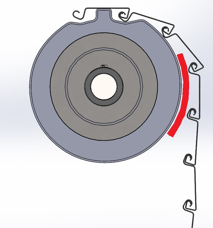
Copyright 2020 Wayne Dalton, a division of Overhead Door Corporation 10STEP 3
LOCATE HOOD STRAPS & FLAME BAFFLE
This Section Applies to Between Jambs (Brackets Under Lintel) Shutters Only:
(Skip to Step #4 if Shutter is “face mounted” i.e., brackets above lintel.)
If the brackets are “under lintel”, the mounting holes for the hood straps and flame baffle must be drilled prior to erecting the barrel and curtain assembly. Temporarily attach
the brackets to the guides. (Refer to Figure 6A). Position each hood strap tightly against and flush with the front and bottom of each bracket as shown in Figure #6A. The back
of the hood strap should loop over the top and back side of the guide.
NOTE: A 1” TO 1-1/2” SPACE EXISTS BETWEEN THE TOP OF THE BRACKET AND THE BOTTOM OF THE LINTEL, SINCE FIRESTAR SHUTTERS ARE DESIGNED TO
EXPAND UPWARD (SEE INSTALLATION DRAWING FOR EXACT DIMENSION).
Clamp the hood straps to the guides temporarily and use the straps as a template to scribe the location of the mounting holes under the lintel. Position the flame baffle (if
provided) under the lintel as shown in Figure #6B with the hinge to the back and centered between the hood straps. A clearance of 1/8” should be held from edge of the
baffle to the inside face of the hood straps (see Figure #6B). Check to see that the baffle swings down freely and also will catch on the flame baffle fuse (attached to the front
hood) which supports it. Mark the position under the lintel for three equidistant holes through the hinge. Remove the flame baffle, hood straps, and brackets and drill the
marked holes in the lintel.
Figure 6A Figure 6B
344940 REV2 03/17/2020 ©
Copyright 2020 Wayne Dalton, a division of Overhead Door Corporation 11STEP 4A
BARREL/BRACKET ASSEMBLY – MANUAL LIFT-UP AND AWNING CRANK OPERATED.
WARNING
SPRINGS ARE CLOSER TO ONE SIDE OF BARREL ASSEMBLY, CAUSING THAT SIDE TO BE HEAVIER. BARREL ASSEMBLY WILL FALL IF LIFTED FROM CENTER. TO AVOID
POSSIBLE SEVERE OR FATAL INJURY, CAREFULLY DETERMINE BALANCE POINT, PRIOR TO LIFTING BARREL ASSEMBLY, TO PREVENT BARREL ASSEMBLY FROM FALLING.
WARNING
BRACKET ASSEMBLIES CAN BE HEAVY. TO AVOID POSSIBLE INJURY, PERSONS WITH LIFTING LIMITATIONS SHOULD NOT PERFORM THIS NEXT STEP.
Lay the barrel assembly in front of the opening. Note the sticker located on the barrel. This sticker will indicate the operated end, the direction the curtain uncoils to close the
shutter, and the spring turns required to balance the shutter. Slide the set collar, and then the thrush bearing, onto the push down shaft. Slide the brackets onto the barrel
shaft extensions and place the brackets on wood blocks. Install a cotter pin onto the barrel shaft extension (with the flat) (do not install the adjusting wheel at this time).
Install the sprocket, ¼” shaft key, and snap ring onto the shaft. Locate the sprocket so that it contacts the snap ring, and tighten the set screws. Next, move the inner set collar
and thrust bearing (between the barrel and inside surface of the bracket) against the inside bearing race on the bracket, and tighten the set screws (prevents lateral barrel
shaft movement).
IMPORTANT: DETERMINE PROPER ORIENTATION OF
BARREL AS INDICATED BY STICKER ON BARREL
(EXAMPLES BELOW).
Right Hand Sticker
Left Hand Sticker
344940 REV2 03/17/2020 ©
Copyright 2020 Wayne Dalton, a division of Overhead Door Corporation 12WARNING
SECURE BRACKET TO BARREL ASSEMBLY USING SUPPLIED COTTER PIN, OR VISE GRIPS, TO PREVENT IT FROM SLIDING OFF DURING LIFTING. FAILURE TO SECURE
BRACKET TO BARREL ASSEMBLY COULD RESULT IN SEVERE OR FATAL INJURY.
CAUTION
ALL PARTS (EXCEPT KEYS) ARE DESIGNED FOR A SLIP FIT. FORCING PARTS TOGETHER MAY RESULT IN DAMAGE LEADING TO MALFUNCTION.
STEP 4B
BARREL/BRACKET ASSEMBLY –TUBE MOTOR OPERATED.
Install the operating bracket assembly while the barrel is
still resting on the wooden blocks.
LEFT HAND TUBE MOTOR OPERATED SHOWN
STEP 4C
BARREL/BRACKET ASSEMBLY –GCX MOTOR OPERATED.
Slide the brackets onto the barrel shaft extensions and place the brackets on wood blocks. The GCX operator will be installed after the barrel and brackets are secured to the
guides. (Step 10C).
STEP 5
ATTACHING BRACKETS TO GUIDES.
Determine the best method of lifting the barrel and brackets to prevent damage during installation.
WARNING
BRACKET AND BARREL ASSEMBLY ON LARGER SHUTTERS, PARTICULARLY WITH AN OPERATOR, CAN BE EXTREMELY HEAVY. PERSONS WITH BACK PROBLEMS OR OTHER
PHYSICAL CONDITIONS WHICH MAY LIMIT THEM FROM LIFTING HEAVY OBJECTS SHOULD NOT PERFORM THE NEXT STEP. USE A MULTI-PERSON CREW OR LIFTING
EQUIPMENT SUCH AS A FORKLIFT WHEN APPROPRIATE.
344940 REV2 03/17/2020 ©
Copyright 2020 Wayne Dalton, a division of Overhead Door Corporation 13WARNING
SECURE BRACKETS TO BARREL ASSEMBLY TO PREVENT IT FROM SLIDING OFF DURING LIFTING, POSSIBLY CAUSING SEVERE OR FATAL INJURY.
Lift the barrel and brackets to the bracket mounting holes provided on the channel shaped outer guide. Bolt the bracket and guides together, making sure the bracket is posi-
tioned inside the guide.
IMPORTANT: THE BOLT HEADS MUST BE ON THE INSIDE
(THREADED SECTION OUT) TO PREVENT INTERFERENCE
WITH THE OPERATION OF THE COIL.
STEP 6
ATTACHING CURTAIN.
Position the curtain assembly parallel with the door opening so that the top attachment slat is in front of the rest of the curtain (the hinged part
away from the opening).
CAUTION
Do not attempt to slide forks of lift truck directly between floor and curtain. Permanent door damage may result.
WARNING
CURTAIN MUST BE SECURELY ATTACHED TO LIFTING MECHANISM. OTHERWISE, CURTAIN COULD FALL CAUSING POSSIBLE SEVERE OR FATAL INJURY.
Lift curtain assembly (centered between guide assemblies) and suspend approximately one foot below the barrel assembly, using ropes or straps of adequate strength to
safely support curtain assembly weight. Remove steel banding from around curtain assembly.
WARNING
BANDING IS UNDER TENSION. TO AVOID POSSIBLE INJURY, WEAR EYE PROTECTION AND DO NOT STAND IN FRONT OF BANDING WHEN CUTTING IT.
344940 REV2 03/17/2020 ©
Copyright 2020 Wayne Dalton, a division of Overhead Door Corporation 14Rotate barrel assembly until top slat attachment point is accessible. Feed top slat around back side of barrel assembly until top slat is out in front of barrel assembly. Install the
top slat attachment bolts and nuts, verifying that the curtain is centered between the brackets.
Continue rolling the curtain up around the barrel assembly until the entire curtain is coiled onto the barrel assembly. Clamp or block the guide assembly approximately 6”
down from the top of the guides. Loosen the safety ropes enough to let the curtain feed into the guide grooves.
WARNING
NO TENSION HAS YET BEEN APPLIED TO DOOR. IF CURTAIN IS ALLOWED TO ROTATE AND FREE FALL, SEVERE OR FATAL INJURY COULD RESULT. KEEP THE CURTAIN
SECURE AND PREVENT FROM ROTATING.
STEP 7
INSTALLING INNER GUIDE ASSEMBLY
With the curtain and barrel assembly (not shown for clarity) now mounted to the guides and secured to prevent curtain from dropping, proceed to install the inner guide
assembly. Position the bottom bar inside the channel shaped outer guides approximately 3”-4” below the top of the guide opening.
Install the bottom bar stops to the inner guides as shown in Detail ‘B’.
Position the correct inner guide into the outer guide so that the inner angle holes line up with the outer guide slots. Attach the inner guide using the truss head bolts and
acorn nuts that were shipped installed in the guide assembly.
Repeat this procedure with the opposite guide assembly.
Install the slide lock strike tabs (if ordered with locks).
344940 REV2 03/17/2020 ©
Copyright 2020 Wayne Dalton, a division of Overhead Door Corporation 15DETAIL A
A
B
INNER GUIDE ASSEMBLY
DETAIL B
STEP 8
APPLYING COUNTERBALANCE SPRING TENSION (MANUAL LIFT-UP, CRANK, AND GCX MOTOR OPERATION ONLY).
The amount of initial revolutions (IR’s) as indicated on the installation drawing and on the barrel “rev tag” is the THEORETICAL STARTING POINT for the required spring tension.
In most cases this figure is correct, but due to variations in steel, springs, friction, etc., slight adjustments may be required.
CAUTION
ALWAYS WIND COUNTERBALANCE SPRING TENSION WHEN THE SHUTTER IS IN THE UP POSITION. THE SPRINGS ARE UNDER THE LEAST AMOUNT OF TENSION AT THIS
POINT.
WARNING
VERIFY THAT AT THIS POINT, THE ADJUSTING WHEEL IS FREE AND THERE IS NO SPRING TENSION.
Install the adjusting wheel and cotter pin as shown. Using approved winding bar, rotate the adjusting wheel (AW) slightly in both directions to de-
termine the neutral point of the tension shaft. Insert the two winding bars securely into the holes in the AW as shown on page 18.
344940 REV2 03/17/2020 ©
Copyright 2020 Wayne Dalton, a division of Overhead Door Corporation 16IMPORTANT: TENSION IS APPLIED IN THE DIRECTION AS THE SHUTTER WOULD TURN AS IT COILS UPWARD (OPPOSITE THE DIRECTION OF THE ARROW ON THE “REV
TAG”).
Hint: If conditions permit, use wall as brace for winding bar for a safe procedure of installing the AW pin as shown.
WARNING
EXERCISE CAUTION WHEN APPLYING OR ADJUSTING SPRING TENSION. CONTACT WITH RAPIDLY ROTATING ADJUSTING WHEEL OR EXPELLED WINDING BAR CAN CAUSE
SERIOUS INJURY OR DEATH. USE TWO (NOT PROVIDED) WINDING BARS 1/2” DIAMETER STEEL ROD, MINIMUM 18 INCHES LONG.
NOTE: Apply the initial revolutions (IR’s) marked on the rev tag and installation drawing. The IR’s are the required number of turns (of the spring) to hold the curtain in the
open position.
While holding the winding bar firmly in one hand, insert the AW pin with the other hand
through the lug in the bracket and into the hole in the AW to lock the AW at the specified
number of revs. Remove winding bars.
IMPORTANT: APPLY ONLY ENOUGH TENSION TO HOLD THE SHUTTER IN THE UP POSITION
AGAINST THE BOTTOM BAR STOPS. THIS IS THE OPTIMUM SETTING, AS TOO MUCH TENSION
COULD PREVENT THE SHUTTER FROM DROPPING WHEN THE RELEASE LEVER OR FUSIBLE LINK
IS ACTIVATED.
STEP 9
TESTING THE SHUTTER BALANCE (Manual Lift-Up, Crank, GCX Motor Operator Only)
With the adjusting wheel locked, operate the shutter through several cycles to check shutter balance. If the shutter does not balance properly and requires further spring
adjustment, repeat the procedure for “Applying Tension” to add or remove spring tension. Ideally, the shutter should have sufficient spring tension to just allow the shutter to
stay up in the open position and no more.
CAUTION
INCREASING THE INITIAL TENSION WILL REDUCE THE LIFT EFFORT BUT CAN PREVENT AUTOMATIC CLOSURE WHEN REQUIRED TO DO SO UNDER ACTUAL FIRE
CONDITIONS. DO NOT OVERWIND.
344940 REV2 03/17/2020 ©
Copyright 2020 Wayne Dalton, a division of Overhead Door Corporation 17STEP 10
LEVEL DOOR (IF NEEDED)—If during previous step the door rolled up level and straight, skip this step.
A. Check that guides are plum, square, level, and are properly mounted onto floor and wall.
B. Check that the pipe is level.
C. Check that the attachment of the curtain is straight on the pipe.
If all of the above is correct and the door still rolls up out of level, a shim may need to be added, as shown in
Figure 19.
Shim materials: Bottom Bar Not Level
• A piece of rubber is the desired material for a shim.
• A piece of cardboard could be used but may deteriorate over time.
• Use a 1/8” x 6” x 6” thick piece of material and increase thickness or pieces depending on the result acquired,
as shown in Figure 20.
Application of shim:
• To determine the side in which the shim will be applied, the door will need to be in the open position.
• When facing the door, the bottom bar will be unleveled. The lower side of the bottom bar will be the side in Figure 19
which the shim needs to be placed.
• The hood may need to be loosened or removed for the application of the shim. Curtain
To apply the shim, two laborers might be required.
Installing the shim:
D. Close the door fully.
E. When door is at bottom make sure door is in hand chain mode.
F. Turn off the power to the motor (if applicable) to ensure safe application of the shim.
G. Backwind the door using the chain. Lock chain in place using chain keeper.
WARNING
When the door is wound backwards there is a force in which the door will want to wind forward.
Secure the door in this position by locking hand chain onto chain keeper to prevent injury.
H. As the curtain is wound backwards apply the shim to the lower side between the pipe and slats or on the
ring of the low side.
I. Restore power to the motor (if applicable).
J. Check the level of the bottom bar while door is in the open position. If it is not level, add a second shim and Shim
Pipe Ring
check again.
NOTE: If the door has wind locks there may be some stacking interference in the wind locks as the door is
wrapping during operation. This is a normal characteristic. For wind lock applications the doors bottom bar
should be level at the open position. Figure 20
344940 REV2 03/17/2020 ©
Copyright 2020 Wayne Dalton, a division of Overhead Door Corporation 18STEP 11A
MANUAL LIFT-UP AND CRANK OPERATION: Installing the drop mechanism components.
IMPORTANT: STEP 8, WINDING THE COUNTERBALANCE SPRING, MUST BE COMPLETED PRIOR TO PERFORMING THESE NEXT STEPS. DOOR MUST BE IN FULLY CLOSED
POSITION FOR STEP 11A.
Install the clutch disks onto the 3/4” diameter shaft. Install the slotted sprocket, spacer, ¼” shaft key and ratchet tension wheel as shown. Fasten the cotter pin in the end of
the 3/4” shaft, to secure the components from moving laterally. Tighten all set screws on the door sprocket and inner set collar. Verify that the clutch disks rotate freely. Orient
the clutch disks and slotted sprocket as shown below:
RIGHT HAND OPERATED
NUT (FACTORY SLOTTED SPROCKET
INSTALLED
ON SPROCKET)
ROTATE THE SLOTTED SPROCKET CLOCKWISE
(LOOKING AT END OF OPERATOR BRACKET)
UNTIL ALL THE NUTS ON THE TWO SPROCKETS
AND CLUTCH DISKS ARE IN CONTACT.
STOPS ON CLUTCH DISKS (MUST BE ORIENTED AS SHOWN)
BRACKET SHOWN
CUT AWAY
NUT (FACTORY INSTALLED ON SLOTTED SPROCKET)
344940 REV2 03/17/2020 ©
Copyright 2020 Wayne Dalton, a division of Overhead Door Corporation 19LEFT HAND OPERATED
SLOTTED SPROCKET NUT (FACTORY
INSTALLED
ON SPROCKET)
ROTATE THE SLOTTED SPROCKET COUNTERCLOCKWISE
(LOOKING AT END OF OPERATOR BRACKET)
UNTIL ALL THE NUTS ON THE TWO SPROCKETS
AND CLUTCH DISKS ARE IN CONTACT.
STOPS ON CLUTCH DISKS (MUST BE ORIENTED AS SHOWN)
NUT (FACTORY INSTALLED ON SLOTTED SPROCKET) BRACKET SHOWN
CUT AWAY
Install the chain from the slotted sprocket to the idler sprocket, and if crank operated, install the chain from the drive sprocket on the awning crank to the door sprocket.
Adjust each chain so that there is 1/4” to 1/2” of
slack as shown for proper operation and automatic
closure functionality. The idler sprocket and chain
tension is adjustable by loosening the mounting
NO CHAIN OR CRANK
bolts on the opposite side. (If the idler sprocket FOR LIFT-UP DOOR
IDLER SPROCKET
MOUNTING BOLTS
location is adjusted, the centrifugal clutch chain
tension will also require adjustment). Re-tighten all
INSTALL CHAIN
bolts & nuts.
IDLER SPROCKET
CENTRIFUGAL CLUTCH MOUNTING BOLTS
CHAIN INSTALLATION FOR LIFTUP AND CRANK DOORS
WARNING
EXERCISE CAUTION WHEN APPLYING, ADJUSTING, AND SECURING SPRING TENSION. CONTACT WITH RAPIDLY ROTATING TENSION WHEEL OR EXPELLED WRENCH CAN
CAUSE SERIOUS INJURY OR DEATH.
WARNING
ACTIVATING THE TEST HANDLE WILL RELEASE SPRING FORCES, CAUSING THESE PARTS TO SPIN RAPIDLY AND CAN POTENTIALLY CAUSE SEVERE INJURY TO ANY PERSON
IN CONTACT. ENSURE RELEASE LEVER AND TEST HANDLE ARE IN THE LOCKED POSITION AND SECURED BEFORE AND DURING THE TIME YOU PERFORM THIS STEP.
Now, the push-down spring (connected to the 3/4” diameter shaft) must be wound. The shutter must be in the CLOSED position. Install the test handle, fusible links, turn-
buckles and cable and attach to the release lever (per Step 11). Rotate the release lever upwards and secure it so that the ratchet tooth engages the tension wheel
344940 REV2 03/17/2020 ©
Copyright 2020 Wayne Dalton, a division of Overhead Door Corporation 20teeth. Using a pipe wrench, rotate the tension wheel downwards (towards the floor) and apply 1-1/2 to 1-3/4 full turns of tension on the push-down spring. Install the (2)
5/16” -18 x 1-1/4” carriage head bolts through the slotted sprocket, spacer, and ratchet tension wheel and tighten them securely with the washers, lock washers, and 5/16”
nut. ATTACH CABLE 'S' HOOK,
FUSIBLE LINK, AND
CABLE HERE
RELEASE LEVER
5/16" x 1-1/4
CARRIAGE BOLTS
APPLY TURNS 5/16" NUTS
DOWNWARDS AND WASHERS
RATCHET TOOTH
STEP 11B
TUBE MOTOR OPERATION
Install the tube motor, wiring, and push button, and set the door limits per the tube motor supplied instructions.
NOTE: The test handle must be engaged to operate the shutter.
STEP 11C
GCX MOTOR OPERATION
Install the GCX operator to the bracket with (4)
3/8”-16x1-1/4” button cap screws, nuts, and wash-
ers as shown. Install the door srocket, roller chain,
operator wiring, and push button, and set the door (4) 3/8" NUTS, LOCK WASHERS, WASHERS
FUSE CABLE
limits per the GCX operator supplied instruction
CABLE PULLEY
manual. The drop lever must be installed so that it DROP LEVER
is perpendicular to the floor, when the fuse cable
in routed and the test handle is engaged. The fuse
cable should be routed so that it forms a 90° angle
(approximate) to the drop lever (see Figure 11C). MANUAL
RELEASE ARM
NOTE: The test handle must be engaged to operate
the shutter.
(4) 3/8"-16x1-1/4 BTN CAP SCREW Figure 11C
FIG 10C
344940 REV2 03/17/2020 ©
Copyright 2020 Wayne Dalton, a division of Overhead Door Corporation 21STEP 12
FUSIBLE LINKS AND CABLE ROUTING
Fusible links are designed to melt in the event of a fire and are shipped in a
package with the door. The links must be located in such a way that they will
be exposed to any fire that may be inside the building. If shutters are installed
on both sides of the opening, it is recommended that the cables and fusible
links should be interconnected so that both shutters close during a test or
detector activation. The Authority Having Jurisdiction may require this, and
Factory Mutual (FM) requires this.
CAUTION
PER NFPA 80 FUSIBLE LINKS MUST BE LOCATED NO MORE THAN
18 INCHES BELOW THE CEILING ON BOTH SIDES OF THE SHUTTER
OPENING, AND NEAR THE SHUTTER OPENING ON THE SIDE THE
SHUTTER IS MOUNTED.
IMPORTANT: THE RELEASE LEVER MUST DROP REGARDLESS OF WHICH CON-
NECTION IN THE CABLE SEPARATES.
In addition to fusible links, some codes and construction will require the door
to be integrated into the building’s fire alarm system. This can be done with
electro-mechanical devices such as the Waynegard . For such devices, see the
installation instructions included with them.
Generally any fusible link must be at least 6” away from any fixed point (ex:
turnbuckle, pulleys etc.) or sufficient enough that the drop out mechanism
and tension release arm can swing down (see Appendix D for additional infor-
mation).
A FUSE LINK HOUSING IS REQUIRED IF A DROP CEILING EXISTS ABOVE THE SHUTTER OPENING IN ORDER TO COMPLY WITH THE PROVISIONS OF NFPA 80 AND IN
ORDER TO KEEP THE FUSE LINK EXPOSED TO THE HEAT OF A POTENTIAL FIRE, RATHER THAN BEING LOCATED ABOVE THE DROP OR FALSE CEILING.
Install the test handle as shown. Adjust cable tension using turnbuckles.
STEP 13
TEST DROP PROCEDURE
Prepare to Test Drop:
IMPORTANT: PRIOR TO DROPPING THE SHUTTER, ENSURE THE SHUTTER OPERATES FREELY AND PROPERLY IN NORMAL OPERATION.
WARNING
REMOVE THE AWNING CRANK WINDING SHAFT PRIOR TO TEST DROPPING THE SHUTTER! THE AWNING CRANK ROTATES RAPIDLY DURING TEST PROCEDURE, AND
COULD CAUSE SEVERE INJURY.
344940 REV2 03/17/2020 ©
Copyright 2020 Wayne Dalton, a division of Overhead Door Corporation 22WARNING
ROPE OFF THE OPENING TO KEEP PERSONS FROM ENTERING AREA DURING TEST DROP. ENSURE ALL PERSONS ARE KEPT CLEAR OF THE OPENING AND THE OPENING IS
FREE OF OBJECTS AND DEBRIS. THE SHUTTER DESCENDS RAPIDLY DURING TEST PROCEDURE AND COULD CAUSE SEVERE INJURY.
Test drop the shutter as follows:
Activate the test handle. Record the amount of time the shutter takes to close and verify it closes between 6 to 24 inches per second. To reset the shutter, insert the pin into
the test handle. For tube motor or GCX motor operated shutters, the shutter is ready to be operated.
NOTE: For GCX operators, verify that the manual release arm travels fully upward, to re-engage the operator, as shown in Figure 11C.
For manual lift-up and crank operated shutters, the push-down spring must be reset. This is accomplished by raising the shutter to the fully open position. At this point the
shutter is ready for normal operation, no tools are required. Repeat procedure to verify it is working correctly. Complete the release form in the back of this manual and return
it to the factory.
STEP 14
VERIFY DROP SPEED.
For manual lift-up operated or crank operated shutters: if drop speed is less than 6” per second, increase the push-down spring tension. If the drop speed is more than 24” per
second, reduce the push-down spring tension. (per step 11A). If the drop speed cannot be adjusted to within 6” and 24” per second, contact Wayne-Dalton.
STEP 15
HOODS, SUPPORTS & HOUSINGS (UNDER LINTEL)
(Skip to next section for brackets mounted above lintel)
HINT: LOWER THE SHUTTER TO OFFER THE MAXIMUM
CLEARANCE BETWEEN THE COIL AND THE LINTEL.
REFER TO FIGURE #21 AND #22. INSTALL THE FLAME
BAFFLE AND HOOD STRAPS IN THE LINTEL HOLES
PREPARED EARLIER. TEST THE FLAME BAFFLE FOR
FREEDOM OF MOVEMENT. IT SHOULD HAVE THE ABIL-
ITY TO SWING DOWN AND REST ON THE BARREL/COIL
ASSEMBLY WITHOUT RESTRICTING DOOR OPERATION.
IMPORTANT: THE FRONT HOOD MAY CONTAIN A
FLAME BAFFLE FUSIBLE TAB LOCATED INSIDE. THE
FLAME BAFFLE (IF PROVIDED) MUST REST ABOVE THIS
TAB AND BE CONTAINED BY IT (see Figure #22).
Figure 21
344940 REV2 03/17/2020 ©
Copyright 2020 Wayne Dalton, a division of Overhead Door Corporation 23NOTE: NFPA 80 DOES NOT APPROVE THE USE OF LEAD ANCHORS ON ROLLING FIRE SHUTTER INSTALLATIONS; DO NOT USE LEAD ANCHORS.
Temporarily prop the flame baffle in its upper-most position before attaching the front hood. This will insure it is guided into this position. Remember to remove the props
later. Position the front hood on the hood straps. Align and punch all holes in the hood at the hole locations in the hood straps. Attach the front hood with the self-tapping
screws provided, but do not tighten the screws at this time, since the housings must slide under the front hood.
HINT: IF THE SHUTTER IS MOUNTED TOTALLY UNDER THE LINTEL AND THE FASCIA SIDE IS ACCESSIBLE, IT MAY BE EASIER TO INSTALL THE FRONT HOOD FIRST,
THEN SLIDE IN THE FLAME BAFFLE (IF REQ’D) FROM THE FASCIA SIDE.
Attach the A.W. bracket housing and sandwich the flanges between the hood straps and the front hood (see Figure #23). Check to insure the cutouts, as provided, are large
enough so as not to interfere with the drop arm throughout its travel. Trim if necessary. Now tighten all screws in the vicinity of AW bracket locking hood/housings in place.
Attach the governor bracket housing in similar manner, and proceed to tighten all remaining hood screws. Remove the temporary flame baffle props, making sure only the
fusible tab holds the baffle in its upper position.
Proceed to attach the back hood to the hood straps. Align and punch all holes in the back hood at the points where holes are provided in the hood straps.
Hoods, Supports & Housings (above lintel)
HINT: LOWER THE SHUTTER TO OFFER THE MAXIMUM CLEARANCE BETWEEN THE COIL AND THE LINTEL.
THE FRONT HOOD MAY CONTAIN A FLAME BAFFLE FUSIBLE TAB LOCATED INSIDE. THE FLAME BAFFLE (IF PROVIDED) MUST RESET ABOVE THIS TAB AND BE CONTAINED
BY IT (SEE FIGURE #23 INSET)
Fasten the hood to the existing holes in the bracket flanges using the self-tapping screws provided. Do
not tighten screws at this time, since the housings must slide under the front hood.
Figure 22
344940 REV2 03/17/2020 ©
Copyright 2020 Wayne Dalton, a division of Overhead Door Corporation 24Refer to figure #24. Depending on the width of the hood, extra supports may be required. If hood straps are provided, erect them now. To allow for thermal expansion, locate
the connecting screws in the bottom of the slots.
Attach the A.W. bracket housing and sandwich housing flange between bracket flange and front hood (see Figure #23). Check to insure the cut-outs, as provided, are large
enough so as not to interfere with either drop arm throughout its travel. Trim if necessary. Now tighten all screws in the vicinity of A.W. bracket. Attach the governor bracket
housing in similar manner and proceed to tighten all remaining hood screws.
Figure 23
Figure 24
344940 REV2 03/17/2020 ©
Copyright 2020 Wayne Dalton, a division of Overhead Door Corporation 25STEP 16
MISCELLANEOUS FINAL CHECKLIST.
Check the area for any extra parts, and be sure these were not omitted in the installation process.
Recheck all bolted connections to verify all are securely tightened.
Clean up the area and make sure it is secure, with the handle engaged with the pin provided.
If the building owner or facility manager is unfamiliar with the product, demonstrate the operation of the door and any optional equipment before leaving the job site. Be
sure to demonstrate how to safely drop test the door and point out the importance of Pad-Locking the release handle to avoid possible tampering. Have the customer or
his representative sign off on the installation using the “Rolling Fire Door Test Drop Release Form” provided in the hardware bag and also fill out the “Test Drop Release Form”
in the back of this manual. Return a copy of form in the hardware bag to Wayne-Dalton and keep a copy in your maintenance files. Exchange all documentation and keys to
locks at this time. Be sure the customer receives a copy of this manual and of the installation drawing.
Be sure to report (in writing) to the factory any complaints or recommendations the customer may register at the completion of the
installation that may have a bearing on future designs.
IMPORTANT: WARNING LABEL MUST BE APPLIED TO OPERATED SIDE OF THE ROLLING DOOR, ON THE GUIDE, AT EYE LEVEL.
Wayne-Dalton
Rolling Door Division
14512 Lincolnway St E
Dalton, Ohio 44618
344940 REV2 03/17/2020 ©
Copyright 2020 Wayne Dalton, a division of Overhead Door Corporation 26APPENDIX A: OPTIONAL COMPONENTS
MISCELLANEOUS FINAL CHECKLIST.
The following are some examples of common options and adjustments for fire shutters:
SLIDE BOLTS OR CYLINDER LOCKS
Raise the shutter to the open position. Bend the tab on the inside of the guides so that it sticks out about 1/4”. Lower the shutter and try to engage the locks. If the bottom bar
contacts the tab before the door is completely closed, or the locks still do not engage the tab, bend the tab back in so that the casting just clears.
Appendix B: Service Record
This manual is intended for the use of the installer on the job site. It is meant to be informative but not exhaustive. The final word is set out in the specifications and drawings
approved by the purchaser before the door was shipped.
Wayne-Dalton doors should be installed by trained industrial door technicians. Wayne-Dalton dealers have access to technical training courses on rolling fire door products.
This space is for comments regarding maintenance and service. The installer is asked to forward a note to Wayne-Dalton of any unusual facts or damage regarding the instal-
lation or shipment. This manual should be given to the building maintenance supervisor as a guide to maintenance and future repairs.
344940 REV2 03/17/2020 ©
Copyright 2020 Wayne Dalton, a division of Overhead Door Corporation 27APPENDIX C: TROUBLE SHOOTING
WARNING
ALL REPAIRS, ADJUSTMENTS AND MAINTENANCE MUST BE DONE BY A TRAINED ROLLING FIRE DOOR SYSTEMS TECHNICIAN.
The chart below is a list of possible problems with the operation of the fire shutter. The probable causes listed are the most common, and are not meant to include ALL possi-
bilities. With the variety of the product and the field conditions, other factors may be involved.
344940 REV2 03/17/2020 ©
Copyright 2020 Wayne Dalton, a division of Overhead Door Corporation 28APPENDIX D: ADDITIONAL FUSIBLE LINK CABLING
Below are additional details for fire shutters with the coil mounted above ceiling, or a typical modification for electro-mechanical release devices. These are provided as a sam-
ple and may not be right for every installation. The actual field condition at the job site will determine the best cable routings. If you need help determining a cable routing
for your installation contact Wayne-Dalton Technical Service for assistance.
344940 REV2 03/17/2020 ©
Copyright 2020 Wayne Dalton, a division of Overhead Door Corporation 29344940 REV2 03/17/2020 Copyright 2020 Wayne Dalton, a division of Overhead Door Corporation
©
30344940 REV2 03/17/2020 Copyright 2020 Wayne Dalton, a division of Overhead Door Corporation
©
31INSPECTION AND DROP TEST GUIDELINES 12. Check balance and spring tension of door
Refer to the manufacturer’s installation/reset instructions and NFPA-80 13. If chain operated, check hand chain for damaged links. Replace or repair if
VISUAL INSPECTION necessary
14. If motor operated, check door operating jamb sprocket and chain, adjust and
CAUTION
lubricate as necessary. Readjust limits as necessary.
EVERY COMPONENT OF A DOOR AND ITS INSTALLATION MUST BE CHECKED FOR
DETERMINATION OF FACTORS THAT MAY AFFECT A DOOR’S INTENDED OPERATION
C. Ancillary equipment
AND PERFORMANCE. THE LIST BELOW MAY BE INCOMPLETE AND IS PROVIDED AS A
1. Smoke detectors/release devices - check continuity (all release devices must
GUIDELINE ONLY.
be tested)
A. Proper installation requirements 2. Control panels - check function
1. Curtain, barrel and guides must be aligned level, plumb, and true 3. Miscellaneous other equipment should be checked for proper function and
2. Attachment to jambs must be with proper bolts, expansion anchors, or as operation
otherwise required by the listing WARNING
3. Maintain expansion clearance (top of guides for FireStar Fire Shutter)
SERVICING OF MOTOR OPERATOR SHOULD BE DONE BY A QUALIFIED ELECTRICIAN
4. Fusible links must be located at top of door and within 1 foot of ceiling on both
WITH THE NECESSARY SCHEMATICS AND PROPER KNOWLEDGE OF THE OPERATOR.
sides of wall
OPERATIONAL INSPECTION
B. Check and repair damaged, incorrect or missing parts, such as: Roll door up and down in normal operation to check for spring tension and free
1. Slats -bent slats, cracked beads, torn ends movement of curtain in guides.
2. Endlocks - missing, broken, bent, loose
DROP TEST
3. Bottom bar - bent angles, loose bolts, missing washers on bolts (when required)
If the shutter does not roll up and down properly in normal operation, or if there are
4. Guide assembly - bent angles, loose bolts, missing galvanized washers or bolts damaged or missing parts that will create a hazard or prevent proper operation or
(when required) Curtain entry or debris in guide reset, THESE CONDITIONS MUST BE CORRECTED BEFORE CONDUCTING A DROP TEST.
5. Hood and flame baffle (when baffle required) - bent, rubbing curtain in open
position, holes, tears. Attachment to brackets and wall (when required), Drop test per manufacturer’s instructions. Drop test should provide for automatic
intermediate supports (when required) closing of the curtain at an average speed not less than 6 inches per second, nor more
than 24 inches per second, and full closure of the curtain with the bottom bar closing
6. Brackets and operating mechanisms - worn, misaligned or badly meshed gears,
evenly across the sill/floor.
sprockets or chains, broken parts, and bent shafts
7.Automatic closing and governor mechanisms - missing or broken parts, drop or Reset per manufacturer’s instruction. Complete drop test forms and forward copies to
release arms tied, blocked, or wedged Wayne-Dalton dealer and customers.
8. Fusible links, cable, S-hooks, eyes, pulleys, etc. - links painted or coated with dust or
grease, kinked or pinched cable, twisted or not flexible, obstructed eyes or ULTIMATE ACCEPTABILITY OF A FIRE DOOR IS THE DECISION OF THE AUTHORITY
HAVING JURISDICTION, AS DEFINED BY NFPA-80.
raceways
9. Mounting and assembly bolts - missing or loose
10. Guide mounting bolts must all be in top of slot for upward expanding FireStar fire
shutters
11. Past replacement of parts not from the original door manufacturer - “ homemade”
or mismatched parts are not approved and must be replaced.
344940 REV2 03/17/2020 ©
Copyright 2020 Wayne Dalton, a division of Overhead Door Corporation 32FireStar® Fire-Rated Counter
Shutter
Limited Warranty
Wayne Dalton, a division of Overhead Door Corporation ("Seller") warrants to the original purchaser of the
344940 REV2 03/17/2020
FireStar® Fire-Rate Counter Shutter (“Product”), subject to all of the terms and conditions hereof, that the
Product and all components thereof will be free from defects in materials and workmanship for the following
period(s) of time, measured from the date of installation:
©
• 24 MONTHS against defects in materials and workmanship
Seller’s obligation under this warranty is specifically limited to repairing or replacing, at its option, any part
which is determined by Seller to be defective during the applicable warranty period. Any labor charges are
excluded and will be the responsibility of the purchaser.
This warranty is made to the original purchaser of the Product only, and is not transferable or assignable. This
warranty does not apply to any unauthorized alteration or repair of the Product, or to any Product or
component which has been damaged or deteriorated due to misuse, neglect, accident, failure to provide
necessary maintenance, normal wear and tear, acts of God, or any other cause beyond the reasonable control
of Seller or as a result of having been exposed to toxic or abrasive environments, including blowing sand, salt
water, salt spray and toxic chemicals and fumes.
THIS WARRANTY IS EXCLUSIVE AND IN LIEU OF ANY OTHER WARRANTIES, EITHER EXPRESS OR
IMPLIED, INCLUDING BUT NOT LIMITED TO ANY IMPLIED WARRANTY OF MERCHANTABILITY OR
FITNESS FOR A PARTICULAR PURPOSE.
IN NO EVENT SHALL SELLER BE RESPONSIBLE FOR, OR LIABLE TO ANYONE FOR, SPECIAL,
INDIRECT, COLLATERAL, PUNITIVE, INCIDENTAL OR CONSEQUENTIAL DAMAGES, even if Seller has
been advised of the possibility of such damages. Such excluded damages include, but are not limited to, loss
of use, cost of any substitute product, or other similar indirect financial loss.
Claims under this warranty must be made promptly after discovery, within the applicable warranty period, and
in writing to the authorized dealer or installer whose name and address appear below. The purchaser must
allow Seller a reasonable opportunity to inspect any Product claimed to be defective prior to removal or any
alteration of its condition. Proof of the purchase and/or installation date, and identification as the original
purchaser, may be required.
Copyright 2020 Wayne Dalton, a division of Overhead Door Corporation
SELLER:
SELLER’S ADDRESS:
33You can also read