Appendix 26. Tailings Storage Facility Scoping Study - PNX Metals
←
→
Page content transcription
If your browser does not render page correctly, please read the page content below
Appendix 26.
Tailings Storage Facility Scoping
Study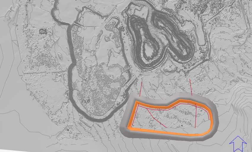
+++++++++++++++++++++++++++
                      Tailings Storage Facility Scoping Study

        Fountain Head Gold Project, Northern Territory
                                               PNX Metals Ltd
                                                          Rev C
                                                     24 May 2021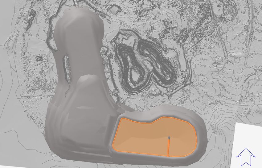
Resource Engineering Consultants Pty Ltd
ACN: 626 931 753

Trading as REC
ABN: 66 626 931 753

Address and Contact Details
Suite 2E, 2 Gemstone Blvd
Carine WA 6020
T: +61 (8) 6444 7988
E: info@rec.com.au
W: www.rec.com.au

                                                       Limitations, Uses and Reliance
 This document, once read in its entirety, may be relied upon for the purposes stated within the limits of:

 Geotechnical investigations and assessments are undertaken in accordance with an agreed term of reference and timeframe and may involve intrusive
 investigations of subsurface conditions, generally at a few selected locations. Although due care, skill and professional judgement are applied in the
 interpretation and extrapolation of geotechnical conditions and factors to elsewhere, the potential for variances cannot be discounted. Therefore, the
 results, analyses and interpretations presented herein cannot be considered absolute or conclusive. REC does not accept any responsibility for variances
 between the interpreted and extrapolated and those that are revealed by any means. Specific warning is given that many factors, natural or artificial, may
 render conditions different from those that prevailed at the time of investigation and should they be revealed at any time subsequently, they should be
 brought to our attention so that their significance may be assessed, and appropriate advice may be offered. Users are also cautioned that fundamental
 assumptions made in this document may change with time and it is the responsibility of any user to ensure that assumptions made, remain valid.

 The comments, findings, conclusions and recommendations contained in this document represent professional estimates and opinions and are not to be
 read as facts unless expressly stated to the contrary. In general, statements of fact are confined to statements as to what was done and/or what was
 observed; others have been based on professional judgement. The conclusions are based upon information and data, visual observations and the results
 of field and laboratory investigations and are therefore merely indicative of the environmental and geotechnical conditions at the time, including the presence
 or otherwise of contaminants or emissions. In addition, presentations in this document are based upon the extent of the terms of reference and/or on
 information supplied by the client, agents and third parties outside our control. To the extent that the statements, opinions, facts, conclusions and/or
 recommendations in this document are based in whole or part on this information, those are contingent upon the accuracy and completeness of the
 information which has not been verified unless stated otherwise. REC does not accept responsibility for omissions and errors due to incorrect information
 or information not available at the time of preparation of this document and will not be liable in relation to incorrect conclusions should any information be
 incorrect or have been concealed, withheld, misrepresented or otherwise not fully disclosed. We will not be liable to update or revise the document to take
 into account any events, emergent circumstances or facts occurring or becoming apparent after the date of this document.

 Within the limitations imposed by the terms of reference, the assessment of the study area and preparation of this document have been undertaken and
 performed in a professional manner, by suitably qualified and experienced personnel, in accordance with generally accepted practices and using a degree
 of skill and care ordinarily exercised by geotechnical consultants under similar circumstances. No other warranty, expressed or implied, is made.

 This document has been prepared for the purposes stated herein. Every care was taken in the interpretation of geotechnical conditions and the nature and
 extent of impacts, presentation of findings and recommendations which are provided in good faith in the general belief that none of these are misleading.
 No responsibility or liability for the consequences of use and/or inference by others is accepted.

 Intellectual and copyright in the information, data and representations such as drawings, appendices, tabulations and text, included in this document remain
 the property of REC. This document is for the exclusive use of the authorised recipient(s) and may not be used, copied or reproduced in whole, or in part,
 for any purpose(s) other than that for which it was prepared for. No responsibility or liability to any other party is accepted for any consequences and/or
 damages arising out of the use of this document without express and written consent.

 The above conditions must be read as part of the document and must be reproduced where permitted. Acceptance of this document indicates acceptance
 of these terms and conditions.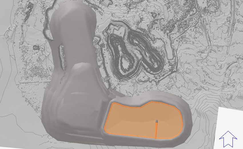
Report
Title:           Tailings Storage Facility (TSF) Scoping Study

File:            P19-05-PR-04

Author(s):       Mitch Hanger; Joshua Blake

Client:          PNX Metals Ltd

Contact:         Craig Wilson

Synopsis:        This document presents the Scoping Study design of the Tailings Storage Facility at the Fountain Head Gold Project

Revision
          Date                   Revision        Purpose                                                         Author

   21 MAY 2021                    REV A          ISSUE FOR REVIEW AND COMMENT                                    MH; JB

   22 MAY 2021                    REV B          ISSUE FOR REVIEW AND COMMENT                                    MH; JB

   24 MAY 2021                    REV C          ISSUE FOR REVIEW AND COMMENT                                    MH; JB

                     Recipients are responsible for eliminating all superseded documents in their possession

Distribution
          Date                  Revision       Approved               Recipient(s)                                  No of Copies

   21 MAY 2021                   REV A         MH                     PNX METALS LTD                             1. PDF

   22 MAY 2021                   REV B         MH                     PNX METALS LTD                             1. PDF

   24 MAY 2021                   REV C         MH                     PNX METALS LTD                             1. PDF

                     Recipients are responsible for eliminating all superseded documents in their possession

                                                                 © REC 2021
Table of Contents
Table of Contents .............................................................................................................. 4
List of Figures .................................................................................................................... 6
List of Tables ...................................................................................................................... 6
List of Appendices ............................................................................................................. 6
Terminology and Abbreviations ....................................................................................... 7
1. TSF Proposal Summary .............................................................................................. 8
             Scope of Works ................................................................................................................ 8
             Guidelines and Information Supplied ................................................................................ 8
2. TSF Design Criteria ..................................................................................................... 9
             Introduction ....................................................................................................................... 9
             Production Parameters ..................................................................................................... 9
             Storage Capacity .............................................................................................................. 9
             Tenure and Site Conditions ............................................................................................ 10
             Climate and Design Rainfall ........................................................................................... 10
             Geology .......................................................................................................................... 11
             Tailings ........................................................................................................................... 11
             2.7.1 Geochemical Testing ........................................................................................................... 11
             2.7.2 Implications for Tailings Management ................................................................................. 12
3. TSF Design ................................................................................................................. 12
             General ........................................................................................................................... 12
             DMIRS Classification ...................................................................................................... 13
             3.2.1 Hazard Rating and Category ............................................................................................... 13
             ANCOLD Consequence Category .................................................................................. 14
             3.3.1 General ................................................................................................................................ 14
             3.3.2 Dam Failure Severity Level ................................................................................................. 14
             3.3.3 Dam Failure Population at Risk ........................................................................................... 14
             3.3.4 Dam Failure Consequence Category .................................................................................. 14
             3.3.5 Environmental Spill Consequence Category ....................................................................... 15
             3.3.6 ANCOLD Design Criteria ..................................................................................................... 15
             Minimum Freeboard ........................................................................................................ 15
             3.4.1 Recommended Freeboard .................................................................................................. 16
             Design Concept .............................................................................................................. 16
             Drainage Design ............................................................................................................. 17
             Embankment Geometry .................................................................................................. 17
             Cut-Off Trench ................................................................................................................ 17
             Liner Details .................................................................................................................... 18
             Underdrainage System ................................................................................................... 18
             Water Management ........................................................................................................ 19
             Water Balance ................................................................................................................ 20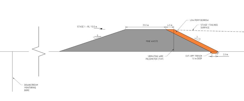
Tailings Placement ......................................................................................................... 20
4. Monitoring and Instrumentation............................................................................... 22
5. Closure and Rehabilitation ....................................................................................... 23
6. Forward Works .......................................................................................................... 24
             Risk Based TSF Design .................................................................................................. 24
             Geotechnical Investigations and Material Testing .......................................................... 24
             6.2.1 Geotechnical........................................................................................................................ 24
             6.2.2 Tailings ................................................................................................................................ 24
             Seismicity Study ............................................................................................................. 24
             Detailed Design Works ................................................................................................... 24
             Construction.................................................................................................................... 25
7. References ................................................................................................................. 26
8. Limitations ................................................................................................................. 27
List of Figures Figure 1: IWL Layout ........................................................................................................................................ 10 Figure 2: IWL General Arrangement (Plan) ...................................................................................................... 12 Figure 3: Freeboard Definition (DMP, 2015) .................................................................................................... 15 Figure 4: IWL Configuration (Section) .............................................................................................................. 17 Figure 5: Cut-off Trench Configuration ............................................................................................................. 17 Figure 6: Underdrainage System Layout .......................................................................................................... 18 Figure 7: IWL Freeboard Assessment .............................................................................................................. 19 Figure 8: IWL Tailings Storage Capacity Curve ............................................................................................... 21 Figure 9: Embankment Instrumentation (Plan) ................................................................................................. 22 Figure 10: Embankment Instrumentation (Section) .......................................................................................... 22 List of Tables Table 1: Production Schedule ............................................................................................................................ 9 Table 2: Design Capacities ................................................................................................................................. 9 Table 3: Climate Data – Fountain Head Gold Project Area.............................................................................. 10 Table 4: Rare Design Rainfall Depths .............................................................................................................. 11 Table 5: DMP CoP Hazard Rating System....................................................................................................... 13 Table 6: DMP CoP Category Rating System ................................................................................................... 14 Table 7: ANCOLD Dam Severity Level Rating System .................................................................................... 14 Table 8: IWL ANCOLD Design Criteria ............................................................................................................ 15 Table 9: DMIRS Freeboard Requirements ....................................................................................................... 16 Table 10: Recommended Freeboard................................................................................................................ 16 Table 11: Water Balance .................................................................................................................................. 20 List of Appendices Appendix A: Preliminary Design Drawing
Terminology and Abbreviations
The following terminology and abbreviations have been used in this document:

AEP            Annual exceedance probability

ANCOLD         Australian National Committee on Large Dams

BOM            Bureau of Meteorology

DITT           Department of Industry, Tourism and Trade (NT)

DMIRS          Department of Mines, Industry Regulation and Safety (WA)

DR             Design Report

DWERS          Department of Water and Environmental Regulation (WA)

GPS            Global Positioning System

GSI            Geotechnical Site Investigation

LOM            Life of mine

IFD            Intensity frequency duration

IPTSF          In-Pit Tailings Storage Facility

IWL            Integrated Waste Landform

m/a            Metres per annum

m3/d           Cubic meters per day

Mm3            Million cubic meters

Mt             Million tonnes

Mt/a           Million tons per annum

NAF            Non-acid forming

OM             Operating Manual

PAF            Potentially Acid Forming

RL             Reduced level

t/a            Tonnes per annum

t/d            Tonnes per day

t/m³           Tonnes per cubic metre

SMDD           Standard maximum dry density

TSF            Tailings Storage Facility

TSM            Tailings storage management
1. TSF Proposal Summary
Resource Engineering Consultants Pty Ltd (REC) has been engaged to prepare this Engineering Feasibility
Study (EFS) level design of the Tailings Storage Facility (TSF) at the PNX Metals Ltd (PNX) Fountain Head
Gold Project (Project) to support the overall project Feasibility Study into the technical and commercial viability
of the Project.

          Scope of Works
The EFS scope of works is based on the proposal and comprises:

      •   Feasibility Study level Embankment Design;

      •   Sizing based on data provided by PNX and others;

      •   Preparation of an EFS Design Report; and

      •   Preparation of EFS Drawings (preliminary design drawings).

          Guidelines and Information Supplied
The following information has been provided by PNX for reference:

      •   PNX CAD files, detailing the project site ground surface topographic contours, planned alignment and
          tenement boundaries;

      •   PNX presentation slides illustrating the proposed IWL concept, and tailings and waste storage
          requirements;

      •   Geochemical Characterisation of Fountain Head CIL Tailings, by Environmental Geochemistry
          International, dated 16 March 2021;

      •   Prefeasibility Study - Hayes Creek Project, Tailings Storage Facility, IPTSF Concept Hayes Creek
          Project, by Land & Marine Geological Services Pty Ltd, dated 2 June 2017;

The following publicly available information has also been referenced:

      •   Bureau of Meteorology (BoM) website

          (http://www.bom.gov.au/jsp/ncc/climate_averages/evaporation/index.jsp?period=an#maps).

Reference: P19-05-PR-04                             Page 8 of 27                                  Date: 24 May 2021
Site: Fountain Head Gold Project              Title: TSF Scoping Study                                Revision No: C
2. TSF Design Criteria
Introduction
REC was engaged by PNX to prepare the design of the IWL for the Project. As part of the EFS level design of
the IWL, the PNX mine production schedule has been used to volumetrically stage the design the facility.
Production Parameters
The IWL design for the project is based on a 4-year operational life. The Project ore processing route is CIL
and tailings will be filter pressed to form a tailings paste with a moisture content of approximately 10 – 15 %
before being transported to the IWL for dry stacking via heavy earthmoving machinery. The project waste and
tailings production schedule are presented in Table 1.
Table 1: Production Schedule
Material Year 0 Year 1 Year 2 Year 3 Year 4 Total
Waste (Mt) 0 5.39 6.05 5.43 0.88 17.75
Cumulative Waste (Mt) 0 5.39 11.44 16.87 17.75 -
Tailings (Mt) 0 0.68 0.73 0.75 0.56 2.72
Cumulative Tailings (Mt) 0 0.68 1.42 2.17 2.72 -
Storage Capacity
At an assumed average dry density of 2.1 t/m3 for the IWL tailings following completion of the filter pressing
process route, the IWL provides 1.37 Mm3 of storage capacity for 2.87 Mt of tailings across 4 operational
stages. This exceeds the required 1.30 Mm3 of tailings storage capacity for 2.72 Mt over 4 years. The IWL
design stage capacities are presented in Table 2.
Table 2: Design Capacities
Material Stage 1 Stage 2 Stage 3 Stage 4 Total
Embankment Crest Height (m) 113.5 118.0 122.0 125.0 22.5
Assumed Dry Density (t/m3) 2.1 2.1 2.1 2.1
Storage Capacity (Mt) 0.69 0.77 0.76 0.65 2.87
Cumulative Tailings (Mt) 0.69 1.46 2.22 2.87 -
Tailings Storage Capacity (Mm3) 0.33 0.37 0.36 0.31 1.37
3
Tailings Cumulative Capacity (Mm ) 0.33 0.70 1.06 1.37 -
Storage Life (years) 1.0 1.0 1.0 1.0 4.0
Life (Years) 1.0 2.0 3.0 4.0 -
Constructed Tailings Beach Slope (%) 2.75 2.50 2.50 2.25 -
Maximum Waste Crest Height (m) 118.0 125.0 135.0 135.0 40.0
Waste Capacity (Mt) 6.25 6.07 5.48 0.96 18.75
Cumulative Waste Capacity (Mt) 6.25 12.32 17.79 18.75 -
3
Waste Capacity (Mm ) 2.30 2.25 2.03 0.36 6.94
Cumulative Waste Capacity (Mm3) 2.30 4.56 6.59 6.94 -
Reference: P19-05-PR-04 Page 9 of 27 Date: 24 May 2021
Site: Fountain Head Gold Project Title: TSF Scoping Study Revision No: CTenure and Site Conditions
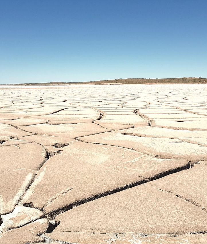
The Project is situated approximately 170 km by road south east of the city of Darwin and can be accessed
from Stuart Highway. The proposed Year 4 IWL configuration is shown in plan on Figure 1.
Figure 1: IWL Layout
Climate and Design Rainfall
Data from the Bureau of Meteorology (BoM) weather station nearest to the site has been used to evaluate the
climate of the project area. Presented in Table 3 are the long-term temperature (1968-2020) for Douglas River
(BoM Site 014901) and rainfall data (1957-2020) for Hayes Creek (BoM Site 014073), located approximately
53 km south east and 14 km south east of the site respectively. Evaporation data for the site was interpreted
from the BoM Evaporation maps and are noted to be ‘Class A evaporation pan’ values.
Table 3: Climate Data – Fountain Head Gold Project Area
Parameter Units Jan Feb Mar Apr May Jun Jul Aug Sep Oct Nov Dec Total
Mean Max. Temp.* °C 33.7 33.5 34.0 34.7 33.3 31.4 31.9 33.6 36.8 37.9 36.9 35.1 -
Mean Min. Temp.* °C 23.9 23.7 23.2 20.5 16.7 13.7 12.9 14.0 18.5 22.3 23.6 23.8 -
Mean Rainfall** mm 290.6 254.4 191.3 65.1 8.2 0.5 1.8 0.9 6.7 39.8 114.6 196.6 1176.2
Highest Rainfall** mm 676.6 543.0 587.5 486.2 112.2 9.0 34.4 20.0 40.6 262.4 248.2 517.5 1737.1
Evap. BoM Interp.*** mm 150 125 150 150 175 162.5 175 200 200 200 250 175 2000
* 1968-2020 (BoM Site 014901); ** 1957-2020 (BoM Site 014073); *** BOM 1975-2005
Reference: P19-05-PR-04 Page 10 of 27 Date: 24 May 2021
Site: Fountain Head Gold Project Title: TSF Scoping Study Revision No: CDesign rainfall depths (mm) for the project site obtained from the BoM 2016 Rainfall IFD (Intensity Frequency
Duration) Data System are shown on Table 4. The design storm storage requirement under DMP (2015) and
ANCOLD (2012) guidelines is for a 1:100 year 72-hour duration rainfall event (highlighted) in Table 4. The
DMP and ANCOLD design storm storage requirements are discussed further in Section 3.2 & 3.3 respectively.
Table 4: Rare Design Rainfall Depths
Annual Exceedance Probability (1 in x)
Event Duration 1 in 100 1 in 200 1 in 500 1 in 1000 1 in 2000
24-hour 287 332 395 447 505
48-hour 382 435 513 577 646
72-hour 439 495 576 641 710
96-hour 475 531 612 676 742
120-hour 495 552 632 694 759
144-hour 504 563 641 702 768
168-hour 507 567 644 703 771
Geology
The Fountain Head group tenements is located within the Pine Creek Geosyncline formation, which is a tightly
folded sequence of fine to coarse grained clastic basinal sediments of Lower Proterozoic age. Over time the
sequence has transformed through metamorphic processes into greenschist facies, with an intrusion of late
syn-orogenic to post orogenic granitoids. A range of economic minerals are now hosted across structurally
permissive sites due to these intrusions and their resulting thermal contact metamorphic and metasomatic
effects.
Fountain Head is located within units of the Mount Bonnie Formation, which is the uppermost division of the
South Alligator Group. Alternative lithologies of siltstone, mudstone and greywacke comprise this group, which
have been metamorphosed into greenschist facies.
Tailings
2.7.1 Geochemical Testing
Preliminary geochemical test results indicate that total Sulphur is not expected to exceed 1.37 % (average of
0.52 % across 5 samples). The tailings samples acid forming results indicate that the tailings have acid forming
potentials ranging from acid consuming to acid forming. Leaching characteristics of the fresh tailings, even in
the absence of oxidation, were indicated to potentially produce leachates containing elevated arsenic
concentrations on contact with water.
Given that some tailings are Potentially Acid Forming (PAF) and elevated arsenic concentrations are expected
in leachate, it is proposed that seepage is controlled by means of a basal liner and underdrainage system. The
basal liner is proposed to comprise borrow material won local to or within the footprint of the IWL. The maximum
permeability of the compacted basal liner is expected to be 5.0 E-9 m/s. On this basis, seepage control by
means of a basal liner and underdrainage system is deemed adequate for the overall environmental control
for the IWL and the EFS level design.
Reference: P19-05-PR-04 Page 11 of 27 Date: 24 May 2021
Site: Fountain Head Gold Project Title: TSF Scoping Study Revision No: C2.7.2 Implications for Tailings Management
In the absence of low permeability oxide tailings with which to line the base of the IWL during commissioning
and early operation, the base (floor) of the IWL will need to include a low permeability basal liner to reduce
seepage.
The installation of an underdrainage system within the IWL is likely to assist in the consolidation of the placed
and compacted tailings and will allow excess water to be removed from the facility. It is envisaged that excess
water removed from the IWL through the underdrainage system will be routed to sumps located to the north of
the facility. Underdrainage water collected in these sumps will be pumped back to the Plant or Evaporation
Pond.
3. TSF Design
General
The objectives of the design of the IWL is to optimise tailings storage capacity, maximise tailings density,
remove water from the facility, reduce seepage and minimising the environmental and societal impact. The
IWL is proposed to be constructed using downstream construction methodology. The downstream
embankments are proposed to be placed and traffic compacted progressively using mine waste produced as
part of mining operations. The upstream face of the embankments is proposed to be constructed using low
permeability materials sourced from nearby areas. The floor of the IWL is proposed to be lined with a
compacted clay basal liner. The remainder of the mine waste produced as part of mining operations is
proposed to form an adjacent Waste Dump.
The proposed Stage 4 IWL configuration relative to the site is shown in Figure 2. The design drawings are
included in Appendix J.
Figure 2: IWL General Arrangement (Plan)
Reference: P19-05-PR-04 Page 12 of 27 Date: 24 May 2021
Site: Fountain Head Gold Project Title: TSF Scoping Study Revision No: CThe conceptual design for the IWL utilises the details discussed in Sections 4 and 5 and the guiding principles
in the following documents:
• Government of Western Australia Department of Mines and Petroleum (DMP): “Guide to
Departmental requirements for the management and closure of tailings storage facilities (TSFs)”,
2015a;
• Government of Western Australia Department of Mines and Petroleum (DMP) Code of Practice (CoP):
“Tailings Storage Facilities in Western Australia”, 2013;
• Australian National Committee on Large Dams (ANCOLD): “Guidelines on the Consequence
Categories for Dams”, 2012; and
• Australian National Committee on Large Dams (ANCOLD): “Guidelines on Tailings Dams Planning,
Design, Construction, Operation and Closure”, 2019.
DMIRS Classification
In the absence of guidelines on TSF design and operation by the Northern Territories Department of Industry,
Tourism and Trade (DITT), the Western Australian DMP CoP in addition to ANCOLD guidelines have been
used to classify the facility.
3.2.1 Hazard Rating and Category
The IWL has been assessed in accordance with the DMP CoP (DMP 2013, Table 1), as being assigned a
‘Medium’ hazard rating, as demonstrated in Table 5. In accordance with the DMP Code of Practice (DMP 2013,
Table 2), the proposed IWL is classified as a “Category 1” facility as the IWL has a hazard rating of ‘Medium’
and the embankment will be greater than 15 m in height, as demonstrated in Table 6.
Table 5: DMP CoP Hazard Rating System
Type of Impact or Damage Hazard Rating Extent or Severity of Impact or Damage
For the proposed location of the IWL the potential population at risk
Loss of human life or personal injury Medium
(ANCOLD terminology) is >1 - 10.
Adverse human health due to direct The potential for human exposure is limited, and temporary adverse health
physical impact or contamination of Medium
effects are possible.
the environment
Livestock are grazed just outside the PNX tenement boundaries,
approximately 200 m – 300 m from IWL. Hence, there is potential for loss
Medium
of livestock from failure. The impact to stock water supply downstream is
acknowledged but considered to be minimal.
Loss of assets due to direct physical
There is mining infrastructure or other mining assets immediately
impact or contamination of the
Medium downstream of the IWL. Temporary loss is acknowledged though repairs
environment
can be made.
Loss of IWL storage capacity is possible. The IWL Stage 4 embankments
Medium will be constructed of placed mine waste to a minimum crest width of 25
m.
The Project is not in close proximity to areas of significant environmental
Medium
value, although temporary damage to the natural environment is possible.
Damage to items of environmental,
heritage or historical value due to
Medium Temporary adverse effects on flora and fauna are possible.
direct physical impact or
contamination of the environment
Low Limited or no potential for damage of items of heritage or historical value.
Reference: P19-05-PR-04 Page 13 of 27 Date: 24 May 2021
Site: Fountain Head Gold Project Title: TSF Scoping Study Revision No: CTable 6: DMP CoP Category Rating System
Maximum Embankment or Hazard Rating
Structure Height (m)
High Medium Low
> 15.0 Category 1 Category 1 Category 1
5.0 - 15.0 Category 1 Category 2 Category 2
< 5.0 Category 1 Category 2 Category 3
ANCOLD Consequence Category
3.3.1 General
There are two Consequence Categories that need to be assessed as part of Tailings Dam design. These are
the Dam Failure Consequence Category and the Environmental Spill Consequence Category. These are used
to determine various design and operational requirements including design of spillways and for flood storage
requirements.
3.3.2 Dam Failure Severity Level
In accordance with ANCOLD (2012) Guidelines there are seven (7) damage type categories that need to be
assessed in order to determine the severity level/impact (Minor, Medium, Major and Catastrophic) of a potential
facility failure or spill. In accordance with the Dam Severity Level impact assessment (ANCOLD 2012, Table
1), the proposed IWL is classified as a ‘Medium’ severity level as detailed in Table 7.
Table 7: ANCOLD Dam Severity Level Rating System
Damage Type Severity Level Severity Level Impact
Infrastructure Medium $10M - $100M production losses and repair costs
Business Importance Medium Significant impacts to operations
Public Health Medium No persons affected
Social Dislocation Minor No persons affected
Impact Area Medium Based on preliminary dam break assessment
Impact Duration Medium Less than 5 years
Impact on Natural Environment Medium Subject to confirmation by others
3.3.3 Dam Failure Population at Risk
The population at risk (PAR) is defined as all people who would be directly exposed to floodwaters assuming
they took no action to evacuate.
No homes, businesses, recreational areas are located downstream of the IWL. However, an existing open pit
(inactive) is located downstream of the embankment, and operational personnel may be present in low lying
areas downstream of the embankment. Based on this, the PAR for the IWL is considered to be greater than
1 but less than 10 (ANCOLD PAR category of >1 to 10).
3.3.4 Dam Failure Consequence Category
The dam failure consequence category is adapted from the severity level assessment of damage and loss,
combined the Population at Risk (PAR).
Reference: P19-05-PR-04 Page 14 of 27 Date: 24 May 2021
Site: Fountain Head Gold Project Title: TSF Scoping Study Revision No: CBased on a dam failure severity level of ‘Medium’ and a PAR >1 to 10, the ANCOLD guidelines recommend
the adoption of a ‘High C’ Dam Failure Consequence Category rating for purpose of the IWL design.
3.3.5 Environmental Spill Consequence Category
The Environmental Spill Consequence Category is assessed by considering the effect of spilling dam water to
the downstream environment (typically through the dam spillway during a flood event). The aerial extent of the
spill impact will be significantly smaller than the area which would be affected in the event of dam failure. The
effect of spilling water to the environment from the IWL is primarily driven by the geochemistry of the tailings
solids and supernatant; see Section 2.5.5.
As the IWL contains dry stacked tailings, no free water resulting from tailings deposition will be stored on the
facility. Consequently, any water stored on the dam will be directly related to rainfall. As such, water spilled
from the dam under extreme rainfall events will consist only of rainfall and will hence be significantly diluted,
and further diluted again given the downstream environment of the dam is also likely to be flooded. Therefore,
the severity of impact on the natural environmental from environmental spills from the IWL would be ‘Minor’.
The PAR assigned to a dam spill is >1 to 10. The combined Dam Spill Consequence Category is assessed as
‘High C’ at this stage of the design.
3.3.6 ANCOLD Design Criteria
The recommended design criteria for a ‘High C’ consequence category facility have been adopted for the
design of the IWL and are presented in Table 8 below.
Table 8: IWL ANCOLD Design Criteria
Parameter Value
Design Storm Event 1:100-year AEP, 72-hour event
Additional Freeboard (Stormwater) 0.5 m
Operating Basis Earthquake (OBE) 1:475-year up to 1:1,000-year AEP
Safety Evaluation Earthquake (SEE) 1:2,000-year AEP
Minimum Freeboard
Freeboard has been assessed according to the DMP (2015) guidelines, and comprises three distinct elements,
namely: operational freeboard, beach freeboard and total freeboard. These elements are graphically illustrated
in Figure 3, and are summarised in Table 9, where:
• Operational freeboard is the height difference between the tailings beach and the embankment crest;
• Beach freeboard is the level difference between the tailings beach and the decant water level plus
allowance for the 1 in 100-year average recurrence interval (ARI), 72-hour rainfall event, and;
• Total freeboard is the sum of the operational freeboard and beach freeboard plus allowance for the 1
in 100-year average recurrence interval (ARI), 72-hour rainfall event.
Figure 3: Freeboard Definition (DMP, 2015)
Reference: P19-05-PR-04 Page 15 of 27 Date: 24 May 2021
Site: Fountain Head Gold Project Title: TSF Scoping Study Revision No: CTable 9: DMIRS Freeboard Requirements
Parameter Value
Operational Freeboard 0.3 m
Beach Freeboard 0.2 m
Total Freeboard (minimum) 0.5 m
3.4.1 Recommended Freeboard
Based on the DMIRS Classification and ANCOLD Consequence Category assessment, the total freeboard (to
maximum operating pond level) adopted for the purpose of the design is presented below in Table 10. The
maximum operating pond level, normal operating pong level, design storm event volume and freeboard levels
for Stage 6 are presented in Section 3.5.6.
Table 10: Recommended Freeboard
Parameter Value
Operational Freeboard (DMIRS minimum) 0.3 m
Beach Freeboard (DMIRS minimum) 0.2 m
Additional Stormwater Freeboard (ANCOLD ‘High C’) 0.5 m
Total Freeboard (minimum to max. operating pond) 1.0 m
Design Concept
The IWL is proposed to be constructed using downstream construction methodology. The downstream
embankments are proposed to be placed and traffic compacted progressively using mine waste produced as
part of mining operations. The upstream face of the embankments is proposed to be constructed using low
permeability materials sourced from nearby areas. The floor of the IWL is proposed to be lined with a
compacted clay basal liner. The remainder of the mine waste produced as part of mining operations is
proposed to be placed around the downstream zone to form an IWL.
At each Stage, filter pressed tailings will be dumped within the facility and compacted to form a graded slope
from the embankments towards the centre of the facility. The tailings will be required to be placed at specific
slopes, depending on the stage of operation and varying between 2.25 % and 2.75 %, to ensure sufficient
stormwater storage is provided across the IWL.
Reference: P19-05-PR-04 Page 16 of 27 Date: 24 May 2021
Site: Fountain Head Gold Project Title: TSF Scoping Study Revision No: CA decant facility will be located in the centre of the facility, with the purpose of capturing and removing incidental
rainfall accumulated across the tailings surface.
Drainage Design
The IWL is designed such that tailings will be dumped within the facility with a graded slope from the
embankments towards a centrally located decant. This will facilitate any incidental rainfall forming a decant
pond located away from the embankment, reducing the potential for phreatic conditions (pore pressures) from
developing beneath and with the main embankment.
Embankment Geometry
The proposed future IWL embankment raises (Stage 1 to Stage 4) are proposed to be constructed using mine
waste. These perimeter embankments will be constructed progressively as waste is produced and hauled to
the IWL. The upstream batter of each raise will be compacted to form a low permeability face comprising clayey
borrow material won from a nearby location. The proposed IWL final configuration is shown in section in Figure
4. Note that the design geometry is based on the known volumes of mine waste at the time of the preparation
of this document.
Figure 4: IWL Configuration (Section)
Cut-Off Trench
A cut-off trench is proposed as part of the construction of the IWL embankment. The trench aims to intercept
lateral seepage through and beneath the embankment. The configuration of the trench relative to the
embankment is shown in Figure 5.
Figure 5: Cut-off Trench Configuration
Reference: P19-05-PR-04 Page 17 of 27 Date: 24 May 2021
Site: Fountain Head Gold Project Title: TSF Scoping Study Revision No: CLiner Details
Based on nearby investigations at the WSD, the floor of the IWL and foundation of the embankments is
expected to comprise a 1.5 m – 3.0 m thick layer of clayey materials overlying Phyllite bedrock. This is expected
to provide a low-permeability floor for the IWL. An underdrainage system has been incorporated into the
concept design. In the absence of low permeability oxide tailings with which to line the base of the IWL, the
base (floor) of the IWL will need to include a clay liner to reduce seepage. The installation of an underdrainage
system within the IWL is likely to assist in the consolidation of the tailings and removal of excess water from
the facility.
Underdrainage System
An underdrainage system has been incorporated into the concept design. In the absence of low permeability
oxide tailings with which to line the base of the IWL, the base (floor) of the IWL will need to include a clay liner
to reduce seepage. The installation of an underdrainage system within the IWL is likely to assist in the
consolidation of the tailings and will allow excess water to be removed from the facility.
It is envisaged that excess water removed from the IWL through the underdrainage system will be routed to
sumps located to the north of the facility. Underdrainage water collected in these sumps will be pumped back
to the Plant or Evaporation Pond.
It is recommended that an underdrainage system is installed as detailed on the drawings attached to this
design report. The proposed underdrainage system layout is presented below in relation to the Stage 1
embankment configuration.
Figure 6: Underdrainage System Layout
Reference: P19-05-PR-04 Page 18 of 27 Date: 24 May 2021
Site: Fountain Head Gold Project Title: TSF Scoping Study Revision No: CWater Management
Assessment of freeboard has been conducted taking into consideration the ANCOLD Guidelines on Tailings
Dams – Planning, Design, Construction, Operation and Closure (ANCOLD, 2012) and the Code of Practice
(CoP): Tailings Storage Facilities in Western Australia (DMP, 2013). The proposed IWL does not receive
rainfall runoff from an upstream catchment. It is assumed that only the low permeability face and tailings
surface contributes to the IWL catchment.
The IWL freeboard was assessed as shown on Figure 7 (top-down approach); the figure shows that based on
a maximum operating pond level of RL 122.8 m, there is sufficient freeboard to contain a 1:100 AEP 72-hour
storm event whilst maintaining 1.0 m of freeboard to the crest. The storm water storage capacity is dependent
upon the actual beach slope constructed during tailings placement and the volume estimate for the IWL is
based on a 2.25 % beach slope at Stage 4.
Figure 7: IWL Freeboard Assessment
0.0
UPSTREAM CREST OF MAIN EMBANKMENT (RL 125.0 m)
DMIRS OPERATIONAL FREEBOARD (300 mm minimum)
MAX TAILINGS LEVEL @ EMBANKMENT (RL 124.7 m)
DMIRS BEACH FREEBOARD (200 mm minimum)
0.5 MINIMUM OPERATING POND
FREEBOARD (2,200 mm)
Freeboard from Perimeter Embankment Crest (m)
ANCOLD ADDITIONAL FREEBOARD (500 mm minimum)
1.0
MAXIMUM POND LEVEL AFTER 1:100 YEAR 72 HR RAINFALL EVENT (RL 124.0 m)
1.5
1:100 YEAR 72 HOUR
EVENT DISPLACEMENT
2.0
MAX OPERATING POND LEVEL (RL 122.80 m) MAXIMUM OPERATING POND
STORAGE CAPACITY - 5.9 ML
2.5
3.0
0 10,000 20,000 30,000 40,000 50,000 60,000 70,000 80,000 90,000 100,000
Water Storage Volume (m3 )
These freeboard requirements are only applicable at the end of the operation of the facility (i.e. dam full
tailings). During the operational life of the IWL the risk of overtopping is significantly reduced as the incidental
rainfall is contained within the IWL and should not be allowed to pond on the tailings surface. Removal of
stormwater is managed by designing the decant pumps to extract not only the volume of water required for the
target dry density, but also the volume of water expected from the 1:100 AEP 72-hour storm event.
It should be noted that the maximum pond level (RL 122.8 m) could be a combination of small storm events
prior to a 1:100 AEP 72-hour storm event; i.e. the maximum pond level at a dam full (tailings) scenario should
not be viewed as a maximum operating level under normal circumstances. The freeboard assessment should
be revisited prior to reaching dam full of tailings to assess if the above Stage 4 beach slope has been
constructed.
Reference: P19-05-PR-04 Page 19 of 27 Date: 24 May 2021
Site: Fountain Head Gold Project Title: TSF Scoping Study Revision No: CWater Balance
A preliminary Water Balance was prepared using an excel spreadsheet for the IWL. The spreadsheet
calculates an estimation of the inflows and outflows from the IWL and determines the balance after plant water
requirements have been met. Water shortfall or water in excess of requirements is indicated on a monthly and
annual basis.
Due to the operation of the IWL as a dry stack tailings facility, water inflows consist solely of incidental rainfall.
Water outflows consist of retention of water within tailings and seepage, however these are negligible
compared to the rainfall inflows.
The following information was used for the water balance:
• Average monthly rainfall figures for Douglas River (BOM Station 014073) adjacent to the site
(recording period: 1957 to 2020).
The following assumptions were made for the water balance:
• Runoff co‐efficient of 1.0 for the surface of the tailings;
• Runoff co‐efficient of 0.0 for the upstream catchment (permeable mine waste);
• The maximum tailings surface area of the IWL, 12.1 ha, was used in this water balance.
Based on the above information the following preliminary water balance was produced:
Table 11: Water Balance
Parameter Units Jan Feb Mar Apr May Jun Jul Aug Sep Oct Nov Dec
Mean Rainfall* mm 290.6 254.4 191.3 65.1 8.2 0.5 1.8 0.9 6.7 39.8 114.6 196.6
3
Rainfall Inflow m 35,163 30,782 23,147 7,877 992 61 218 109 811 4,816 13,867 23,789
Rainfall Inflow tph 47 46 31 11 1 0 0 0 1 6 19 32
* 1968-2020 (BoM Site 014901)
It is recommended that the water recovery system (decant pumps and piping) has a minimum capacity of not
less than 50 m3/hr for the project, to ensure adequate water removal, particularly during high rainfall periods.
Tailings Placement
Tailings are expected to be delivered from the Plant at a production rate of 750,000 tonnes of solids per annum
(tpa) for 4 years (base case production scenario). At times throughout the mine plan, the rate of tailings
production may increase or decrease. The solids content (% solids) is expected to be between approximately
85 % and 90 %.
Filter pressed tailings will be dumped within the facility and traffic compacted to form a graded slope from the
embankments towards the centre of the facility. The tailings will be required to be placed at specific slopes,
depending on the stage of operation and varying between 2.25 % and 2.75 %, to ensure sufficient stormwater
storage is provided across the IWL. The decant facility will be located in the centre of the facility, with the
purpose of capturing any incidental rainfall captured across the tailings surface.
Development (filling) of the IWL is shown graphically on Figure 8 in terms of storage volume and tailings surface
level.
Reference: P19-05-PR-04 Page 20 of 27 Date: 24 May 2021
Site: Fountain Head Gold Project Title: TSF Scoping Study Revision No: CFigure 8: IWL Tailings Storage Capacity Curve
130
TSF Max Storage Capacity
125
Tailings Surface Level (m RL)
Embankment Max Tailings Level
120
115
110
105
0 200,000 400,000 600,000 800,000 1,000,000 1,200,000 1,400,000 1,600,000
Tailings Storage Capacity (m3)
Reference: P19-05-PR-04 Page 21 of 27 Date: 24 May 2021
Site: Fountain Head Gold Project Title: TSF Scoping Study Revision No: C4. Monitoring and Instrumentation Groundwater monitoring bores are to be installed in the area downstream of the IWL to enable any deep‐ seated seepage beneath the perimeter embankment to be identified. In addition to monitoring for seepage from the IWL, a series of monitoring points, comprising Vibrating Wire Piezometers (VWP) will need to be installed at IWL to enable monitoring of the phreatic surface and of pore pressures within the embankment. The VWPs are to be installed as part of the Stage 1 embankment construction and the proposed locations of the VWPs are presented in plan in Figure 9 and in section in Figure 10. Figure 9: Embankment Instrumentation (Plan) Figure 10: Embankment Instrumentation (Section) Reference: P19-05-PR-04 Page 22 of 27 Date: 24 May 2021 Site: Fountain Head Gold Project Title: TSF Scoping Study Revision No: C
5. Closure and Rehabilitation
It is understood that a detailed Project Closure Plan will be developed by others. The proposed IWL and IPTSF
has been developed with closure in mind, taking into consideration;

      •   The DMP’s principal closure objectives for rehabilitated mines - Guidelines for Preparing Mine Closure
          Plans (DMP, 2015b);

               o    (physically) safe to humans and animals,

               o    (geo-technically) stable,

               o    (geo-chemically) non-polluting/non-contaminating, and

               o    capable of sustaining an agreed post-mining land use.

      •   The Environmental Protection Authority’s (EPA) objective for Rehabilitation and Decommissioning to
          ensure that premises are decommissioned and rehabilitated in an ecologically sustainable manner.

A low permeability cover will be required of be constructed over the IWL. This cover will consist of 0.5 m of
compacted clay with an overlying 1.5 m of oxide waste rock, covered by 300 mm of topsoil. Oxide waste
material will be stockpiled around the IWL embankments during operation, ready to be pushed out over the
IWL at closure. This will provide long term containment and erosion protection of the tailings, as well as provide
a suitable medium for re-establishment and sustenance of vegetation. The closure concept for the IWL utilises
the closure surface to spill incidental rainfall.

The decant system may remain in place or on standby until the tailings surface cover has been installed; to
provide an interim means of surface water removal. Further detail around decommissioning of the IWL should
be coordinated with the project-wide decommissioning and closure plan.

A rehabilitation plan will be developed in conjunction with a site wide closure plan. Rehabilitation should involve
respreading collected topsoil on top of the IWL tailings surface, following the placement of compacted clay and
oxide waste rock. Excess topsoil should also be placed on the lower downstream batter surfaces where
available. Topsoil surfaces may require ripping and seeding with native species in order to promote
revegetation, and consequently blend the IWL into the natural landscape and promote evapotranspiration.

It’s important that batter slopes function as erosion resistant water shedding structures. A thin layer of topsoil
should be spread on the downstream batter surfaces mixed in between waste to promote revegetation. The
outer slopes should have no berms, banks, moonscapes or rip lines as these pond water which inevitably result
in piping failure or off-contour rip line breakout gullying.

Reference: P19-05-PR-04                                  Page 23 of 27                            Date: 24 May 2021
Site: Fountain Head Gold Project                    Title: TSF Scoping Study                          Revision No: C
6. Forward Works
Risk Based TSF Design
Prior to progressing the IWL through to Detailed Design (DD) level for regulatory approval, a risk assessment
of the IWL design should be completed with information collected from the works detailed in the following
sections.
Geotechnical Investigations and Material Testing
6.2.1 Geotechnical
A suitable Geotechnical Site Investigation (GSI) will be required across the footprint of the proposed IWL. The
scope of the GSI should comprise the excavation of test pits across the base of the proposed IWL to identify
the underlying lithology. The collection of bulk samples and laboratory testing will be required in order to
understand the characteristics and shear strength of the underlying units.
As part of the GSI a search for potential borrow material sources and laboratory testing should be undertaken
in order to identify local material suitable for the use in construction the low permeability face of the IWL.
In addition, sampling and characterisation should be undertaken on Mine Waste planned to be used to
construct the downstream portions of the IWL.
6.2.2 Tailings
At the time of writing this report, preliminary representative primary tailings sample test results were not
available for analysis. As part of future works, a suite of tailings testing will be required on samples
representative of those to be placed within the IWL. A list of preliminary tailings testing is presented below:
• Particle Size Distribution (PSD) with hydrometer (AS 1289 3.6.3, 3.5.1 and 2.1.1).;
• Atterberg limits test (AS 1289 2.1.1, 3.1.1, 3.1.2, 3.2.1, 3.3.1, and 3.4.1);
• Air‐drying tests (not an Australian Standard Test); and
• Settling tests (undrained and drained) (not an Australian Standard Test).
The results of this tailings testwork should be used in future works to verify the suitability of the proposed
design.
Seismicity Study
A desktop assessment of the IWL needs to be undertaken to confirm the seismicity characteristics of the site
to ensure the IWL is designed to withstand the required earthquake loads over the operating life of the facility.
Detailed Design Works
Following the completion of the works detailed above, the detailed design works will need to be completed,
which include the following:
• Preparation of the Design Report, which encompasses the basis of design and results from various
analyses including seepage, stability, dam break etc., executed as part of the design works;
• Preparation of design drawings and materials take off;
Reference: P19-05-PR-04 Page 24 of 27 Date: 24 May 2021
Site: Fountain Head Gold Project Title: TSF Scoping Study Revision No: C• Preparation of an Operations Manual for the operation and management of the IWL;
• Preparation of instrumentation and monitoring details, to enable the performance of the IWTSF to be
compared against the design criteria;
• Preparation of Closure and Rehabilitation details.
Construction
Following the completion of the detailed design works, the following construction planning works will need to
be completed:
• Planning of mine waste and tailings placement for day-to-day operations;
• Identification of a suitable water source for the conditioning of construction materials;
• Construction of a borrow pit, within which material suitable for the use in construction of the low
permeability face of the IWL can be excavated and conditioned;
Reference: P19-05-PR-04 Page 25 of 27 Date: 24 May 2021
Site: Fountain Head Gold Project Title: TSF Scoping Study Revision No: C7. References
1. ANCOLD 2012, Australian National Committee on Large Dams: Guidelines on the Consequence
Categories for Dams
2. ANCOLD 2019, Australian National Committee on Large Dams: Guidelines on Tailings Dams Planning,
Design, Construction, Operation and Closure
3. ANCOLD 2019, Australian National Committee on Large Dams: Guidelines for Dams and Appurtenant
Structures for Earthquakes
4. BoM 2016/17, Bureau of Meteorology Website
5. DMP 2013, Code of Practice (CoP): Tailings Storage Facilities in Western Australia
6. DMP 2015, Guide to Departmental requirements for the management and closure of tailings storage
facilities (TSFs)
7. DMP 2015, Guidelines for Preparing Mine Closure Plans
8. DMP 2015, Guide to the preparation of a design report for tailings storage facilities (TSFs)
9. Johns, C. A., ‘Geotechnical Properties of Mine Tailings and Implication for Tailings Storage Facility Design’
Proceedings of GEO2010, Calgary, Alberta.
Reference: P19-05-PR-04 Page 26 of 27 Date: 24 May 2021
Site: Fountain Head Gold Project Title: TSF Scoping Study Revision No: C8. Limitations Resource Engineering Consultants Pty Ltd (REC) has prepared this geotechnical report for the Scoping Study level design of the Integrated Waste Landform (IWL) at the PNX Metals Ltd (PNX) Fountain Head Gold Project. This report is provided for the exclusive use of PNX and their consultants for this project only and for the purposes as described in the report. Any party so relying upon this report beyond its exclusive use and purpose as stated above, and without the express written consent of REC, does so entirely at its own risk and without recourse to REC for any loss or damage. In preparing this report REC has necessarily relied upon information provided by the client and/or their agents. The results provided in the report are indicative of the sub-surface conditions on the site only at the specific sampling and/or testing locations, and then only to the depths investigated and at the time the work was carried out. Sub-surface conditions can change abruptly due to variable geological processes and also as a result of human influences. Such changes may occur after REC’s field testing has been completed. REC’s advice is based upon the conditions encountered during this investigation. The accuracy of the advice provided by REC in this report may be affected by undetected variations in ground conditions across the site between and beyond the sampling and/or testing locations. The advice may also be limited by budget constraints imposed by others or by site accessibility. This report must be read in conjunction with all of the attached and should be kept in its entirety without separation of individual pages or sections. REC cannot be held responsible for interpretations or conclusions made by others unless they are supported by an expressed statement, interpretation, outcome or conclusion stated in this report. This report, or sections from this report, should not be used as part of a specification for a project, without review and agreement by REC. This is because this report has been written as advice and opinion rather than instructions for construction. The contents of this report do not constitute formal design components such as are required, by the Health and Safety Legislation and Regulations, to be included in a Safety Report specifying the hazards likely to be encountered during construction and the controls required to mitigate risk. This design process requires risk assessment to be undertaken, with such assessment being dependent upon factors relating to likelihood of occurrence and consequences of damage to property and to life. This, in turn, requires project data and analysis presently beyond the knowledge and project role respectively of REC. REC may be able, however, to assist the client in carrying out a risk assessment of potential hazards contained in this report, as an extension to the current scope of works, if so requested, and provided that suitable additional information is made available to REC. Any such risk assessment would, however, be necessarily restricted to the geotechnical components set out in this report and to their application by the project designers to project design, construction, maintenance and demolition. Reference: P19-05-PR-04 Page 27 of 27 Date: 24 May 2021 Site: Fountain Head Gold Project Title: TSF Scoping Study Revision No: C
You can also read