END-OF-LIFE RUBBER ADDITIVE MANUFACTURING WITH LIQUID LATEX AND RECYCLED
←
→
Page content transcription
If your browser does not render page correctly, please read the page content below
ADDITIVE MANUFACTURING WITH LIQUID LATEX AND RECYCLED
                      END-OF-LIFE RUBBER
                              Miguel Angel Quetzeri Santiago (+ Co-first author)

                        Clara Louise Hedegaard (+ Co-first author, * Corresponding author)

                                            Jose Rafael Castrejón-Pita
                                                r.castrejonpita@qmul.ac.uk

   School of Engineering and Materials Science, Queen Mary University of London
                       Mile End Road, E1 4NS, London, UK
Abstract
Elastomers and rubber are common industrial materials used for test objects, supporting parts, and
many other commercial products. The industrial processing of these materials is currently dominated by
injection moulding, which reduces manufacturing costs, and speeds up production. However, this
manufacturing method does not permit personalisation or customisation, and lacks the versatility of
other techniques such as 3D printing. Understandably, there has been a move towards additive
manufacturing (AM) with elastomers. This work proposes a new approach to AM with liquid latex, using
a drop-on-demand (DoD) based inkjet to fabricate latex patterns. The print-head actuator benefits from
a higher material compatibility compared to conventional inkjet/extrusion-based printers, allowing the
jetting of viscous fluids as well as liquids with high solids loading. The set-up allows printing with
viscous liquid latex of a high solid content (60 wt. %). The process is controllable and reliable, making
the printing of patterns possible. Additionally, we explore printing with micronized rubber powder
(MRP) made from end-of-life tires, to test solid-particle loading compatibility, and as a novel method for
rubber recycling. Here, we demonstrate that large scale DoD inkjet printing is capable of handling solid
particle loadings of up to 10 wt. % in addition to the high solid content liquid latex. Moreover, multi-
layer objects were created from pure liquid latex as well as from MRP/latex suspensions. Material
characterisation indicates that the stiffness of cured latex is not altered by the addition of MRP but
reduces the maximum elongation length from 750% to 430%. The results highlight the ability to print
with both high particle loading and large particles. This explorative study demonstrates the potential of
AM processes with liquid latex as well as a new approach to tire rubber reuse.

Keywords
3D printing, Rubber, Latex, Recycling, Multi-material printing, Drop-on-Demand

Introduction
Rubber and elastomers are widely used materials in industry1 owing to their advantageous physical properties;
good chemical and structural stability, heat resistance and thermal insulation capability, and high strength to
weight ratio2. Traditional manufacturing with elastomers is often done by moulding and casting. This process
allows for little design flexibility, permits mass production but is not flexible to produce one-off products. As
such, there has been a move towards developing additive manufacturing (AM) techniques for elastomer/rubber
production. For example, thermoplastic elastomers have been fabricated using laser sintering3–5, however the
resultant structures were found to have reduced mechanical properties compared to rubber objects fabricated via
the conventional route. Liquid silicone elastomers have been printed using extrusion based methods6 but this

                                                                                                               1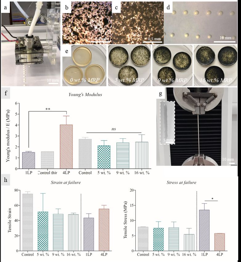
method cannot be applied to a wide range of elastomers due to the restrictions in viscosity. An alternative AM
method for liquid elastomers is drop-on-demand (DoD) inkjet printing.
         DoD inkjet printing allows droplets to be ejected onto a substrate and subsequently cured. Droplets are
conventionally placed adjacently to each other to allow them to coalesce and form a uniform straight array. The z-
axis definition is created by overlaying layers, with intermittent curing or crosslinking steps to ensure adequate
support of subsequent layers. In DoD printing, a pressure pulse induced by thermal, piezoelectric or acoustic
actuation causes a liquid droplet to form and jet from the print-head nozzle. DoD has a number of advantages
above other AM technologies; firstly, there is no substrate contact, avoiding contamination of the nozzle, and
secondly, higher printing speeds can be achieved compared with for example fused deposition modelling (FDM)7.
Moreover DoD methods allow a greater control and variability of the droplet volume and speed8,9. In addition, it
is a digital technology with great flexibility that naturally permits personalisation and one-off production.
Unfortunately, material compatibility is an issue in commercial inkjet systems as the technology is restricted to
operate under a narrow window of liquid viscosities.
         Recent advanced in the field, includes examples of the rubber latex being successfully printed using inkjet;
Raza et al. used a commercially available Microfab print-head to print low melting point alloys and elastomers10,
and Lukić et al. printed diluted liquid latex (35 wt. % solid content) with a commercially available piezoelectric
inkjet printer5. Whilst these examples show that progress has been made, the techniques still suffer from similar
limitations in ink viscosity, solid content, nozzle clogging, and agglomeration. In addition, inks used in AM
methods have additional requirements to that of deposition resolution, as droplets are required to cure or solidify
fast and leave an adequate footprint to build definition in the z-axis. These restrictions still need to be addressed
to improve 3D printed objects made from viscous or high solid content materials such as bio-gels, conductive
inks, and liquid latex.
         From the limitations in DoD printing, solid particle loading is one of the main limitations across all inkjet
industries. The industry standard for conventional inkjet is a maximum viscosity of 20 cP with a solids loading of
< 10 % per volume, and a particle diameter of no greater than 1/20 of the nozzle diameter5,7,11,12. Whilst being
able to inkjet un-diluted liquid latex is an interesting prospect in itself, the ability to add solid particles to form a
colloidal ink widens the market applications for this technique. The addition of particles can be used to reinforce
the positive mechanical properties or improve other properties such as thermal and electric conductivity, stiffness
or elasticity of a given construct. Moreover, this includes the possibility of reusing discarded rubber materials, in
form of micronized rubber powder (MRP), in the manufacturing of new products.
         In recent years, there has been a move towards producing MRP from waste materials such as tires. Tires
remain a major source of waste, despite an increase in governmental initiatives to promote their recycling. In the
USA alone there are still 67 million tires occupying landfills, and an estimate of 25 % (2010) of all end-of-life tires
are placed into landfills worldwide13. Currently, a mere 10 % of end-of-life tires are recycled to create new
products13. A reason for the low rate is the lack of suitable recycling methods and the limited ability to make new
products with discarded material. MRP has proved to be environmental friendly as it can be obtained
mechanically with no contaminants released to the environment. The benefits, in terms of cost have been
previously demonstrated for manufacturing with MRP, to create moulded and extruded products14–17.
         In this study, we propose to inkjet print with liquid latex, with and without MRP, as a step towards
cheaper mould manufacturing with elastomer/rubber based materials. We introduce a versatile DoD inkjet print-
head capable of printing pure liquid latex containing a 60 wt. % solid content and a liquid viscosity of 21.8 ± 0.2
cP. Moreover, we explore the concept of creating hybrid MRP/latex constructs by using colloidal inks of latex
and MRP. Our results show that, in this instance, the inclusion of MRP does not affect the stiffness of the cured
product. Finally, we demonstrate that this ink can be used to manufacture cured latex patterns by DoD deposition
and natural curing.

1. Materials and Methods
INK COMPOSITION

                                                                                                                       2
Two types of ink formulations were used in this study; pure liquid latex and liquid latex with a suspension of
rubber tire waste or fine rubber powder (parlon powder). Pure liquid latex was acquired from Liquid Latex Direct,
UK. The liquid latex contains 60 % natural rubber, 40 % water and < 0.3 % ammonia. The density was measured
to be 940 ± 50 mg.mL-1 and the viscosity to 21.8 ± 0.2 cP. Suspensions were made using parlon powder and
thereafter with a coarse rubber powder made from of end-of-life rubber, namely, micronized rubber powder
(MRP). Suspensions were made by dispersing the parlon powder or MRP in undiluted liquid latex. The weight
percentage of suspended MRP or parlon powder was calculated as ‘WMRP/(WL+WMRP)’ or ‘WP/(WL+WP)’, where
WMRP, WP and WL refer to the weight of MRP, parlon powder and undiluted liquid latex respectively. Synthetic
white parlon powder was purchased from IONXIA, UK (~66 % chlorine and < 2.5 % toluene) and MRP was
kindly provided by Artis UK. A heterogeneous mixture of MRP was used with a maximum particle size of 0.6
mm. Parlon powder was suspended at concentrations of 3.5 to 6.7 wt. %. MRP was suspended at the
concentration 9.6 wt. % when used for printing. Mechanical testing was carried out on cast and cured latex
samples containing MRP at concentrations 0, 5, 9 and 16 wt. %.

Figure 1. Printing with liquid latex. (a) The experimental set-up showing the GRBL controlled stage and
the print-head mounting (The 9 mL reservoir print-head is shown); (b) Varying the droplet interval
keeping the pulse signal and nozzle diameter constant: from left to right increasing the interval length
from 1s to 5.5 s (inserts show birds-eye perspective); (c) An example of a single layer structure made
from pure liquid latex, using a droplet interval of 2.5 s with two close-ups of the corner resolution. (All
scale bars 1 mm.)

                                                                                                               3
PRINT-HEAD DESIGN
For our experiments, two print-head designs where used. These were manufactured in-house and use loudspeaker
as actuators. In both systems, the actuator, driven by a pulse generator, pushes the liquid through the nozzle to
create a droplet. The print-heads are fed with fresh ink through an attached syringe which in turn is attached to a
fast-acting meniscus controller (Inca Digital Printers Ltd., UK) used to balance the pressure inside the print-head
and the atmospheric pressure, keeping the meniscus pinned at the nozzle. In this manner, a single pulse of
pressure generates a single drop. Two print-head sizes were used to assess their performance with the colloidal
inks. The small print-head uses a 20 mm diameter loudspeaker (8 Ohms, 0.1 W), has an inner a liquid reservoir
volume of 4 mL, and a conical nozzle with an outer diameter of 1.0 mm. The larger print-head uses a Visaton
Structure-Borne Driver loudspeaker (8 Ohms, 25 W) with a 9 mL volume reservoir, and a 0.85 mm conical
nozzle. We claim that these drivers (loudspeakers) have more actuation power than other piezoelectric driven
print-heads, e.g. MicroFab and MicroDrop, so making the printing of high viscosity liquids a reality. The driving
signals on both systems are produced using a TTi pulse generator, an acoustic amplifier, and recorded by a digital
oscilloscope. The waveform is kept to a single pulse, with control over the pulse amplitude and width, to adjust
the droplet speed and size. These print-head designs are further developments (miniaturization and simplification)
of a system presented elsewhere18.
EXPERIMENTAL SETUP
The small print-head was mounted on to a 2D motorised stage while the substrate (Kodak inkjet paper) was
secured to a support at a fixed distance. In contrast, the larger print-head was fixed to a vibration damped support
and the substrate mounted onto the stage (Figure 1a). The printing distance, i.e. the distance from the print-head
to the substrate, was kept constant at approximately 5 mm for both systems. The stages were operated by stepper
motors and controlled by the GRBL protocol. In brief, the GRBL code transforms a digital structure into
coordinates and a series of orders that control the motion of the stepper motors and trigger the jetting of the
print-head. The jetting trigger activates (gated mode) the pulse generation signal that is sent to the speaker to print
on demand. The GRBL properties, stepper speed, and printing frequency were adjusted to obtain a placement
resolution below ~300 um. Both meniscus controllers were set to a negative pressure in the range of 8-9 mm H2O
to keep the meniscus pinned at the nozzle and avoid flooding.
THREE-DIMENSIONAL PRINTING TECHNIQUE
The following procedure was followed for printing; Initial loading of print-head and syringe followed by adjusting
the backpressure. The driving signal for droplet formation was adjusted in terms of pulse duration and intensity
for each ink composition. The printing speed and frequency could be adjusted for each ink and system so that
droplet placement could coalesce and form a continuous line, or form a string of equally spaced separated
droplets. Two-dimensional patterns were created by controllably printing on the substrate, and three-dimensional
constructs were attempted by overlaying consecutive printing layers. Two methods of drying were tested, i)
ambient air curing where individual ~1.0 mm width layers take up to 4 min to solidify, and ii) blowing hot air
(~400 C from a 2.3 W heat gun) onto the individual print layers for 10 s to achieve curing of the pattern surface.
IMAGING
Air dried constructs and ink samples were imaged using standard bright field microscope from Leica Instruments,
USA (Leica MZ12.5 Stereomicroscope with an external light source Leica CLS150X). All standard microscopy
images were analysed using the software ImageJ, with at least five measurements taken per determined value (for
example construct and droplet dimensions).
MATERIAL CHARACTERISATION
An indentation test was run on cast samples (Figure 2e) containing varying concentrations of MRP (0, 5, 9 and 16
wt. %) to determine the effects of rubber on the material stiffness. Three different samples per concentration
were tested, with 2-3 tests on each sample, hence a minimum of 8 tests per concentration. The Young's modulus,
4E, was derived from the resulting force-displacement data. Tensile testing was carried out on printed pure liquid
latex samples (1 layer and 4 layer), as well as on cast latex samples containing varying amounts of MRP (0, 5, 9 and
16 wt. %). All samples tested were of a rectangular shape. The experiments were carried out on an Instron 5566
UTM with a ±100N static load cell and a constant strain rate of 30 mm/min. The tensile stress and strain at the
breaking point were determined from the data, as well as the Young’s modulus. A minimum of 2 samples were
tested per concentration. All geometries for the tensile test, and the values for the obtained strain, stress and
Young’s modulus can be found in Table 1. Representative stress-strain plots are shown in Figure 3. Statistical
analysis was carried out using the software GraphPad Prism 5. A one-way analysis variance (ANOVA) was used,
and a statistical significance was accepted when p≤0.05.
Strain Stress Young’s
L0 W T Modulus*
at failure at failure
mm mm mm mm/mm MPa MPa
Control (0 wt. %) 75.1 ± 3.1 7.9 ± 0.1 2.7 ± 0.2
5 wt. % 51.5 ± 24.3 7.51 ± 2.1 2.1 ± 0.5
2.3 ± 0.6 8.2 ± 0.5 0.5 ± 0.1
9 wt. % 48.5 ± 6.9 7.68 ± 1.9 2.4 ± 0.4
16 wt. % 48.1 ± 1.9 5.44 ± 2.0 2.5 ± 0.7
Control Thin 5.9 1.0 0.2 - - 1.6
1 Layer Print (1LP) 2.3 ± 0.3 1.9 ± 0.2 0.3 ± 0.3 43.4 ± 5.7 13.5 ± 2.1 1.5 ± 0.1
4 Layer Print (4LP) 2.1 ± 0.5 3.5 ± 0.2 1.0 ± 0.1 55.3 ± 4.9 5.8 ± 0.1 4.0 ± 0.8
TABLE 1. Summary table of the samples used for tensile testing and the determined strain and stress values at the
breaking point. All values reported are mean ± standard deviation. *The Young’s modulus is reported as the
average from the indentation and tensile tests.
Results and Discussion
INKJET PRINTING WITH LIQUID LATEX
Initial tests were focused on establishing reliable printing conditions with pure liquid latex, evaluated in terms of
droplet formation and reproducibility, as well as jetting stability over time. Pulse signals were adjusted by changing
the pulse width and voltage, to obtain fully formed droplets and avoid satellite droplets19. Conical nozzles were
used in both printing systems, leading to droplets of uniform size both in-flight and post impact. We have
previously shown that our systems can produce droplet speeds in the range of 0.5-2.0 m.s-1, where droplet
creation was dependent on the ink properties, the nozzle geometry, and the signal voltage and width18. Repetition
rates were restricted by the nozzle re-filling time, i.e. the time taken by the meniscus controller and surface tension
to “fill” the missing/jetted liquid at the reservoir. Given the high viscosity of the liquid latex, a droplet deposition
rate (linear printing speed) of 0.15 cm s-1 was used. Our results indicate that latex droplets produce a footprint
(printing dot size) of twice its original diameter, i.e. a droplet from a 1.0 mm nozzle produces a circular dot
footprint of a 2.2 ± 0.9 mm diameter. Within a range, the droplet size can be adjusted by modifying the pressure
pulse width and amplitude, without having to change the nozzle diameter. Both print-heads were shown to be
capable of jetting pure liquid latex, obtaining consistent jetting with liquid latex containing 60 wt. % solid content
and of relatively high viscosity (21.8 ± 0.2 cP). In conventional DoD printing, often a critical droplet spacing is
defined by which the droplets are close enough to coalesce forming a parallel sided line. Above and below the
critical spacing, either bulging of the line or no coalescence occurs respectively20. Figure 1b shows the range of
droplet intervals tested, keeping the motor speed and nozzle diameter constant. As evident, the deposited latex
droplets remain isolated (un-coalesced) at droplet jetting intervals greater than 2.5 s, whilst reducing the interval to
≤ 2.5 s leads to droplet coalescence and path formation. At smaller droplet jetting intervals, the increased overlap
leads to instability and bulging.
5Under our jetting conditions, continuous printing of pure liquid latex was shown to be consistent and
reliable over periods of up to 1 hour. Figure 1c shows the left-side of a square pattern fabricated with the larger
print-head and using a droplet jetting interval of < 2.5 s. These vertical and horizontal lines demonstrate the
accuracy and stability of the print. The two close-ups seen in Figure 1c show examples of the achievable
resolution at the corners. Printing at corners was controlled by adding a gap at the turning point to minimise
bulging from the potential three-way droplet coalescence, i.e. the corner droplet, and the neighbouring droplets in
the horizontal and vertical direction.
Curing at the nozzle is an important limitation for inkjet printing. Whilst a small nozzle is desired to
produce small drop sizes that dry fast, a small sessile meniscus can cure itself at the print-head during idle times.
In fact, we observed cured menisci blocking nozzles within minutes of stopping printing. In our experiments,
cleaning the nozzle plate with a fibre-free swab was sufficient to unblock the meniscus. In a commercial
application, nozzle unblocking can potentially be done by flushing out the cured meniscus prior to printing.
COLLOIDAL CONSTRUCTS AND INKS
In AM, a degree of versatility in the ink composition is often needed to meet the end product specifications. Ink
formulation normally rely on the addition of solid particles to alter the properties of the end product, such as
reinforce the material strength and durability, or to add colour using pigments. Restrictions in solid particle
loading is a well-known problem in inkjet technology, with conventional printing inks containing < 10 wt. % solid
residue8. Having already shown that the developed system is capable of printing with pure liquid latex of a high
solid content, the next step was to prove the feasibility of printing with a suspension of undiluted liquid latex with
the addition of either parlon powder or MRP (colloidal ink suspension). The test was designed to include MRP
made from end-of-life tire waste. MRP is a heterogeneous mixture of rubber, and is comparatively crude. As such,
preliminary experiments were carried out using fine parlon powder, which has a very narrow size distribution, and
an average particle size in the nanometre range. Colloidal ink suspensions of 3.5 and 6.7 wt. % parlon powder
were prepared and tested in the print-head. In both instances, consistent jetting was observed (example shown in
Figure 2a). The printing of the rubber particle and latex ink was demonstrated by jetting a series of defined arrays
as seen in Figure 2a,d. The parlon powder remained suspended in solution throughout the duration of printing, as
observed through the printed droplets and when inspecting the leftover ink post printing. The quality of the
parlon distribution post printing was analysed using microscopy imagining. The parlon powder was shown to
aggregate in the suspension (Figure 2b-c) leading to a non-uniform size distribution of the suspended particles.
However, the parlon was shown to be well distributed within the ink, such that all droplets contain a homogenous
mixture of liquid latex and parlon powder.
Having shown that a solid loading of fine rubber powder is feasible, our experiments then focused on the
jetting of coarse recycled MRP, which is of greater commercial interest due to its recycling potential. The MRP
used has an average particle size of 0.6 mm, comparatively larger than the parlon powder but with a narrow size
distribution. The parlon powder experiments were repeated using a 9.6 wt. % MRP particle loading. A uniform
droplet size was observed throughout each print, although unlike parlon powder, a non-homogenous distribution
of MRP was visible post curing. Solid tire rubber could be clearly visualised in ~90 % of the droplets. The non-
uniform distribution of MRP can be attributed to two factors; similar to parlon powder, the MRP tended to
aggregate in solution creating large clusters, and secondly, due to the weight of coarse MRP they were more prone
to settle on the bottom of the print-head. This issue is common to all colloidal ink suspensions, and not a
property specific to the liquid latex system. In fact, many commercially available print-heads continuously
recirculate the ink within the print-head to avoid aggregation and clogging the nozzles21,22. Implementing a more
defined and rigours mixing procedure or using smaller particles7, could mitigate agglomeration of the particles in
solution as well as reducing the observed settling in the print-head. Alternatively, gentle vibration of the print-
head reservoir could be introduced.
6
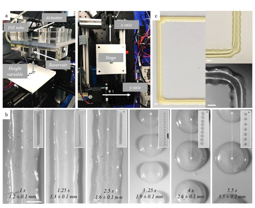
Figure 2Figure 2. Liquid latex with rubber particle loading. (a) Time-lapse of the print-head mounted to the x/y
stage, jetting pure liquid latex (1 drop/1.5 seconds) (scale bar 1 mm); Microscopy images of liquid latex
with (b) 3.5 wt. % and (c) 6.7 wt. % parlon loading; (d) A defined array made by jetting liquid latex
containing 6.7 wt. % parlon powder; (e) Cast rubber samples of pure liquid latex and with increasing MRP
loading (5, 9 and 16 wt. %); (f) A graph of Young’s Modulus, determined using indentation and tensile
testing, of cast samples with 5, 9 and 16 wt. % MRP (control; 0 wt. % MRP), and printed samples of 1 and
4 layers (1LP and 4LP respectively) (control thin: a pure latex cast). Data reported as mean ± standard
deviation; (g) Example of elongation of a 1 layer printed sample (1LP) under a constant strain tensile test
(insert: original sample) and (I) Tensile stress and strain at breaking point, derived from the constant tensile
strain experiments. Data reported as mean ± standard deviation
The impact on the mechanical properties was tested for a range of MRP particle loadings. Samples were
prepared using casting, as shown in Figure 2e, with a range of 0 to 16 wt. % MRP solid content. The samples were
tested by the standard indentation and constant strain tensile tests. The two experimental methods yielded
7comparative values for the Young’s Modulus (the overall mean ± standard deviation are reported in Table 1). The
results indicate that the stiffness of these materials are not greatly affected by the colloid content, and any
differences are within error of each other and not statistically significant (Figure 2f). However, the tensile test
indicates that adding MRP to the latex reduces the maximum elongation length from 750% to 480% (Figure 2h,
strain graph. The ultimate tensile stress (stress at the breaking point) was found to be equal, within error, for all 4
sample types (Figure 2h, stress graph). Having determined the impact of MRP on the mechanical properties, next
the effect of printing was tested. Two types of printed pure liquid latex samples were tested, namely, a one layer
(1LP) and a four layer (4LP) printed rectangle. The stress-strain plots are shown in Figure 3. An example of the
one layer print being tested is shown in Figure 2g. Firstly, in terms of stiffness a higher Young’s modulus was
observed in the case of four layers compared with one layer. However, in both instances the printed samples yield
similar Young’s modulus to the cast controls. The one layer printed line (Figures 2g and 2h) was elongated by 434
± 60 % prior to breaking, whereas the 4 layer printed line (4 layers printed overlaying each other) was elongated
by 553 ± 50 % (Figure 2h). The one layer print showed a higher ultimate tensile stress compared to the 4 layer
print (statistically significant). Overall, we can conclude the droplet-to-droplet and layer-to-layer bonding in the
printing do not significantly change the mechanical properties of the latex, however there is a clear dependency on
sample thickness as seen in the difference of the ultimate tensile stress. Combing these results, we infer that the
effect of MRP particles in latex reduces the elasticity without affecting the stiffness of the printed samples. This is
in line with other works, such as Mueller et al. in 2017, that have established that the global and local mechanical
properties of inkjet manufactured parts can be affected in manufactured mixed-materials parts23
Figure 3. The stress-strain plot for the samples ‘1 Layer Print’, ‘4 Layer Print’ and ‘Control’ (pure latex). All
data points are reported as the mean ± standard deviation
We have demonstrated the ability to print high solid content latex and with suspended recycled rubber,
which from an AM perspective brings new possibilities to the recycling potential of rubber tire waste. There is a
growing market for commercial AM, with many areas of industry yet to take full advantage of this evidence24.
Currently, asphalt and concrete applications where most end of life tires are used or recycled, a maximum of 20
wt. % of rubber is used25,26. In this paper the final 3D printed objects have ≈ 10 wt. % of rubber from tires.
However, in contrast to other recycling methods, 3D printing offers a more versatile way of recycling. Despite
8having an arguably low quantity of MRP in our ink, this technique can be used in the manufacture of commonly
used items, such as for example smartphone cases, in which the market capacity would significantly increase the
quantity of recycled rubber per annum. Another possibility is the printing of thermal insulation for circuits or
protective coatings on electronic components. Moreover, the system has room for incrementing the rubber tire
contents, by for example using finer MRP and/or by diluting the liquid latex. An untested AM option to include a
higher MRP content in the final product, can be to print latex on a powder bed 3D printing mode, whereby the
liquid latex is used to bind the recycled rubber powder on the bed. In this instance, the MRP would have to be
sufficiently fine milled in order for the binding to occur. This method was briefly explored in this study but a
purpose build stage would be needed to achieve high-resolution constructs. Other alternative AM techniques,
such as fused deposition modelling (FDM) or fused filament fabrication (FFF) are not suitable for manufacturing
with tire rubber, as tire rubber does not “fuse” to produce a continuous extruded filament5. The system requires
further development and optimization to be a solution to the tire waste problem, however this is the first step
towards that goal.
Figure 4. Three-dimensional latex constructs. (a) Three layers of pure liquid latex in wet and (b) dry
state, with (c) close-ups of the layer structure; (d) A 3D star construct made from liquid latex with 100
mg/mL (9.6 wt. %) MRP, with (e) close-up of the corners and (f) a side-view; (g) A more complex 1
layer structure made from pure liquid latex and (h) close-ups of the corners and line width
9TRANSITION TO THREE-DIMENSIONAL OBJECTS
Having shown that it is possible to print reliably with liquid latex as well as shown the feasibility of using a
colloidal ink along with the added material benefits, next the possibility of creating three-dimensional objects was
explored. Initially precision and resolution of the system were determined.
In the first instance, pure liquid latex was used. The first patterns created were circles with a diameter of
22 mm (Figure 4a-b), with a droplet interval of 2.5 s to produce a continuous string formation. Three consecutive
layers were completed with intermittent hot air blowing allowing each layer to semi-dry before applying the next
layer. As previously described, two approaches to drying were tested; firstly, drying under ambient air conditions
resulting in 4 min drying time for a ~1.0 mm width layer. The second method consisted in blowing hot air (~400
C) onto the individual print layers for 10 s to achieve a fast curing of the pattern surface. The print resolution was
reduced with increasing layers as evident by the increase in width. This can, for example, be seen in Figure 4a-b,
where the wall thickness of the circular pattern increases from 1.7 ± 0.2 mm at layer 1, to 2.6 ± 0.2 mm at layer 3.
This effect is also the result of the drying/curing speed as the droplet cures into a spherical cap and not as a
pancake shape as in other applications of 3D printing. However, the initial couple of layers retain the precision of
the coordinated stage movement and droplet formation, showing that high resolution is achievable. Connecting
interfaces were visualised using bright field microscopy. Individual droplets were clearly visualised, showing the
layered structure of droplets in the constructs, originating from stepwise layering (Figure 4c). Increasing the speed
of drying between layers would increase the resolution retention.
A star pattern (Figure 4d) was made using a 100 mg.mL-1 (9.6 wt. %) MRP suspension. The construct
thickness measured 1.9 ± 0.4 mm and was made from 15 overlaying layers (Figure 4f). Droplets were in this
instance placed adjacent, but not overlapping in an attempt to mitigate the pronounced bulging instability as
observed with increasing layers27. Whilst finding the critical droplet spacing is the norm in other 3D inkjet-based
printing, in our case the droplets are one order of magnitude larger than conventional DoD. As such, a greater
level of precision is potentially achievable when the droplets are kept adjacent without coalescing, allowing for
each layer to dry in ‘droplet’ shape. Improving the overall resolution would mean decreasing the nozzle diameter
from mm to µm, and thereby increasing control and precision. Smaller DoD systems, such as MicroFab print-
heads were available but not tried as the risk of blocking was very high given the size of particles, the high bulk
viscosity, and the risk of curing at the nozzle. Post drying the construct revealed an increased aggregation of MRP
particles in the pattern, visible as distinctive black patches (Figure 4d-e). At the corners (Figure 4e), the printing
resolution also decreases going from an angle of 42 ± 2 ° to 52 ± 3 °, meaning that sharpness of each corner is
decreased with increasing layers.
Lastly, more complex one-pass printing patterns were attempted using pure liquid latex. Figure 4g-h
demonstrate the ability of our technique to create more complex structures, whilst retaining good placement
resolution. Zooming in on the connection points (Figure 4h) evidence that whilst a clearly defined three-way
corner is possible (top and bottom left), bulging can still occur from three-way coalescence. Further fine-tuning of
the meshing GRBL/G-code instructions at the corners can remove this problem by reducing jetting at the
corners. Whilst the fluid properties and curing mechanisms require further development to decrease the time of
solidification, our results show that single or few layers printing is achievable.
Conclusion
In this paper, we introduce an inkjet based AM process capable of printing with liquid latex with of up to 60 wt.
% solid content and a liquid viscosity of 21.8 ± 0.2 cP, both significantly higher than previous printing methods.
Moreover, this system is able to print with a mixture of liquid latex and tire rubber particles of 0.5 times the
nozzle diameter. Multiple layer objects were fabricated with both pure liquid latex as well as with liquid latex with
the addition of MRP. The Young’s modulus as well as the strain at the breaking point showed no change when
adding the MRP, while maximum elongation length is reduced. Moreover, the printing process does not affect the
Young’s modulus of the objects. The capability of printing with a high particle loading (high solid content latex
with the addition of parlon powder or MRP) and a heterogeneous particle size distribution, shows that the print-
10head design can operate in a wide range of solid particle loadings. This is a great advance, as most conventional
inkjet-based 3D printers cannot operate with viscous liquids or liquids with solid particle loading. The study has
demonstrated the potential of AM with liquid latex, however there is still scope for improvement. For example,
the drying time of the liquid latex should be shortened further, by for example including a heating source in the
stage or in the printing bed. Improvement of the stage and pattern control would enhance the resolution and
reliability of the print quality. A reliable method of AM with liquid latex would bring great merits to the industry,
by reducing cost of manufacturing (no moulds needed), and adding an unprecedented degree of flexibility in the
manufacturing process. Moreover, the study has highlighted a novel method of recycling end-of-life tires. With
this work, it is foreseeable that in the future we can create 3D printed objects with rubber tire waste, expanding
the current recycling and waste management methods.
Acknowledgements
M. A. Quetzeri Santiago acknowledges the funding from the Mexican Energy Ministry (SENER) and the National
Council for Science and Technology (CONACYT) Mexico. We thank Artis UK for providing the micronized
rubber powder. We thank Finn Box from the University of Oxford for his support with the indentation tests, and
Karen Silva Blankenagel from Queen Mary University of London for her support with the tensile tests.
Author Disclosure Statement
No competing financial interests exist.
References
1. Barlow C, Jayasuriya S, Tan CS. The World Rubber Industry.; 2014.
2. Corporation Woodland Plastics. Understanding Thermoset Plastics.
http://www.woodlandplastics.com/understanding-thermoset-plastics.html. Published 2015. Accessed
June 25, 2018.
3. Goodridge R, Tuck C, Hague R. Laser sintering of polyamides and other polymers. Prog Mater Sci.
2012;57(2):229-267.
4. Kruth JP, Levy G, Klocke F, et al. Consolidation phenomena in laser and powder-bed based layered
manufacturing. CIRP Ann - Manuf Technol. 2007;56(2):730-759.
5. Lukić M, Clarke J, Tuck C, et al. Printability of elastomer latex for additive manufacturing or 3D printing. J
Appl Polym Sci. 2016;133(4).
6. Duoss EB, Weisgraber TH, Hearon K, et al. Three-dimensional printing of elastomeric, cellular
architectures with negative stiffness. Adv Funct Mater. 2014;24(31):4905-4913.
7. Guo Y, Huseini SP, Bognet B, et al. Rapid Prototyping Journal Inkjet and inkjet-based 3D printing:
connecting fluid properties and printing performance" Inkjet and inkjet-based 3D printing:
connecting fluid properties and printing performance. Rapid Prototyp J. 2017;23(3).
8. Castrejon-Pita JR, Baxter WRS, Morgan J, et al. Future, opportunities and challenges of inkjet
technologies. At Sprays. 2013;23(6):541-565.
9. Castrejón-Pita AA, Castrejón-Pita JR, Martin GD. A novel method to produce small droplets from large
nozzles. Rev Sci Instrum. 2012;83(11).
10. Raza I, Iannucci L, Curtis PT. Introducing a Multimaterial Printer for the Deposition of Low Melting
Point Alloys, Elastomer, and Ultraviolet Curable Resin. 3D Print Addit Manuf. 2017;4(2):83-89.
11. Derby B, Reis N. Inkjet Printing of Highly Loaded Particulate Suspensions. MRS Bull. 2003;28(11):815-
818.
12. Hon KKB, Li L, Hutchings IM. Direct writing technology-Advances and developments. CIRP Ann -
Manuf Technol. 2008;57(2):601-620.
13. Forrest M. Recycling and Re-Use of Waste Rubber. Shropshire, England: Smithers Rapra Technology Ltd.;
2014. http://app.knovel.com/hotlink/toc/id:kpRRWR0002/recycling-re-use-waste/recycling-re-use-
11waste.
14. Rubber Manufacturers Association. Scrap Tire Markets in the United States, 9th Biennial Report.
Washington; 2009.
15. Aranda Uson A, Ferreira G, Zabalza Bribian I, et al. Study of the environmental performance of end-of-
life tyre recycling through a simplified mathematical approach. Therm Sci. 2012;16(3):889-899.
16. Kind RC. No Title. In: Proceedings of RubberCon. Manchester, UK; 2014.
17. Rosenmayer T, Ayyer R, Papp F. Characterization of Micronized Rubber Powders with cost effective
performance benefits in rubber compounds. In: Annual Technical Conference - ANTEC, Conference Proceedings. ;
2012. https://www.4spe.org/Resources/resource.aspx?ItemNumber=6359. Accessed March 7, 2018.
18. Castrejón-Pita JR, Martin GD, Hoath SD, et al. A simple large-scale droplet generator for studies of inkjet
printing. Rev Sci Instrum. 2008;79(7).
19. Derby B. Inkjet printing ceramics: From drops to solid. J Eur Ceram Soc. 2011;31(14):2543-2550.
20. Derby B. Inkjet Printing of Functional and Structural Materials: Fluid Property Requirements, Feature
Stability, and Resolution. Annu Rev Mater Res. 2010;40(1):395-414.
21. Matsumoto Y, Kobayashi N and Kawamura H. KYOCERA Corp, 2017. Liquid discharge head and
recording device. U.S. Patent Application 15/128,263.
22. Brook C, Ristea A, Walsh M, et al. Xaar Technology Ltd, 2017. Droplet deposition apparatus and method
for manufacturing the same. U.S. Patent 9,566,786
23. Mueller J, Courty D, Spielhofer M, et al. Mechanical Properties of Interfaces in Inkjet 3D Printed Single-
and Multi-Material Parts. 3D Print Addit Manuf. 2017;4(4):193-199.
24. Gordon R. Trends in Commercial 3D Printing and Additive Manufacturing. 3D Print Addit Manuf.
2015;2(2):89-90.
25. Mashaan NS, Ali AH, Karim MR, et al. A Review on Using Crumb Rubber in Reinforcement of Asphalt
Pavement. Sci World J. 2014;2014(i):1-21.
26. Cetin A. Effects of Crumb Rubber Size and Concentration on Performance of Porous Asphalt Mixtures.
Int J Polym Sci. 2013;2013:1-10.
27. Stringer J, Derby B. Formation and stability of lines produced by inkjet printing. Langmuir.
2010;26(12):10365-10372.
12You can also read