SEISMIC DESIGN GUIDE SUSPENDED CEILING SYSTEMS Australia and New Zealand Version 3 - Armstrong World Industries
←
→
Page content transcription
If your browser does not render page correctly, please read the page content below

SEISMIC DESIGN GUIDE SUSPENDED CEILING SYSTEMS Australia and New Zealand Version 3
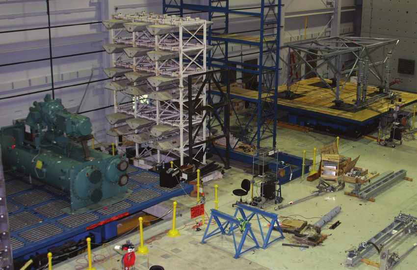
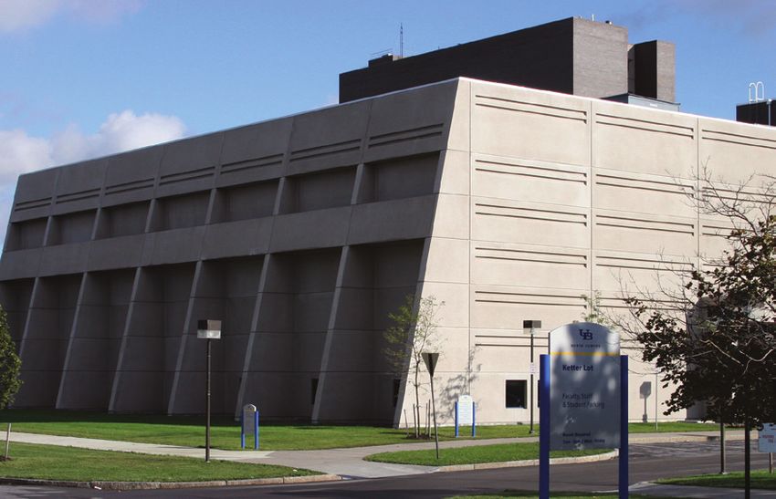
TABLE OF CONTENTS
 WHAT CAUSES SEISMIC ACTIVITY?                                                               4
 ABOUT THIS GUIDE                                                                            5
 SEISMIC DESIGN                                                                              6
 DESIGNING WITH CONFIDENCE USING ARMSTRONG CEILING SYSTEMS                                   7
 LIMITATIONS AND ASSUMPTIONS                                                                 8
 SEISMIC DESIGN CALCULATOR                                                                   9
 SEISMIC DESIGN FORM                                                                        10
 SEISMIC BRACING: LAYOUT OPTIONS                                                            11
 SEISMIC PERIMETER OPTIONS                                                                  12
 PEAKFORM MAIN RUNNER SEISMIC JOINT CLIP                                                    14
 PEAKFORM CROSS TEES SEISMIC JOINT CLIP                                                     15
 SEISMIC PERIMETER TRIMS AND ACCESSORIES                                                    16
 BACK BRACING OPTIONS                                                                       17
 BACK BRACING WITH GRIDLOK ®                                                                20
 SERVICE INTEGRATION AND CLEARANCES                                                         22
 REFERENCE GUIDES FOR DESIGN CALCULATOR                                                     23
       Building Importance Levels                                                            23
       New Zealand locations Hazard Factor (Z)                                               25
       Australian locations Hazard Factor (Z)                                                26

DESIGN STATEMENT
BVT Engineering has been engaged by Armstrong World Industries to assist in the production of
this Suspended Ceiling Seismic Calculator which has been incorporated into this Design Guide. This
Guide and the Seismic Calculators have been prepared to meet the requirements of the Australian
and New Zealand Standards, listed on Page 5.
Testing of the Armstrong Ceiling Grid Systems was undertaken to determine the compression and
tension capacities. Testing of the perimeter fixings and bracing was also undertaken. The values
from this testing have been used in this guide.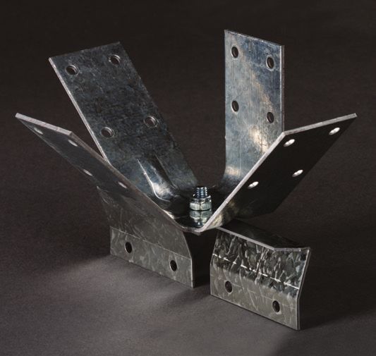
WHAT CAUSES SEISMIC ACTIVITY?
The earth’s surface is made up of a series of (Tectonic) plates that move in relation to each other. The lines where these
plates meet are called fault lines and movement and stresses at these points can send shock waves through the
ground. These shock waves are known as seismic waves and result in vibrations that at their most severe can
cause immense damage to buildings and other structures, communication networks and indeed lives.
TECTONIC PLATES TECTONIC
TECTONIC PLATES
PLATES
TECTONIC PLATES
North American Plate
North American
NorthNorth
American Plate
PlatePlate
American
Eurasian Plate
Juan deTECTONIC
Juan de
Juan de PLATES
Caribbean Arabian Eurasian
Eurasian Plate
Plate
Eurasian Plate
Plate Fuca
Fuca Fuca Plate
Philippine
Plate Plate
Plate
North American PlatePlate Indian
Plate
Caribbean
Caribbean
African Plate Caribbean Arabian
Arabian
Arabian
South Cocos
CocosCocos
American Plate
PlatePlate Philippine
Philippine
Philippine
Nazca Plate
PlatePlate
Plate Plate
Plate
Plate Plate Plate
Plate
Plate
Eurasian Plate Indo-Australian Plate
Indian
Indian
Indian
PlatePlate
Plate
Pacific
Pacific
Pacific
Caribbean Plate Plate
Plate Antarctic Plate
Arabian African
African
African
Philippine PlatePlate
Plate
Plate Plate
Scotia Plate South American Plate
NazcaNazca South
Nazca South American
American
Indian
Plate
PlatePlate
Plate Plate
Plate
Plate
African Plate Indo-Australian
Indo-Australian
Indo-Australian Plate
Plate
Plate
Nazca PLATE TECTONICS
South American
Plate Plate
Indo-Australian Plate
Antarctic
Antarctic
Antarctic Plate
Plate
Plate
ScotiaAntarctic Plate
Scotia
Scotia PlatePlate
Plate
Scotia Plate
PLATE TECTONICS PLATE TECTONICS
uction Lateral Sliding Spreading
PLATE
PLATE TECTONICS
TECTONICS
uction Lateral Sliding Spreading
Subduction Lateral Sliding Spreading
Subduction
Subduction Lateral
LateralSliding
Sliding Spreading
Spreading
4 ARMSTRONG SEISMIC DESIGN GUIDE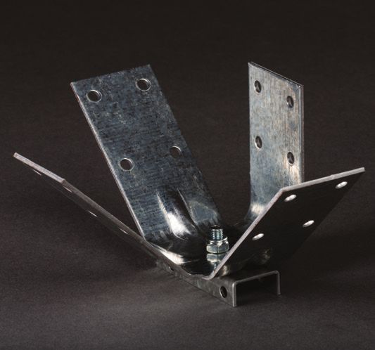
ABOUT THIS GUIDE
         The purpose of this guide is to provide a method for the seismic design of Armstrong suspended grid
         and tile ceiling systems as per the requirements of NZS 1170.5 and AS 1170.4 – Structural Design Actions –
         Earthquake actions.

         The failure of suspended ceilings that are not designed to seismic standards, as a result of
         earthquake activity can have catastrophic consequences, such as:
           • Significant threat of injury or loss of life due to:
                 - Blocked evacuation paths
                 - Falling services
                 - Live loose electrical wires
           • E xtensive delays in recommencing business even though the rest of the building structure may not have
              sustained damage.

         A University of Canterbury report on the Performance of Ceilings in the February 2011 Christchurch Earthquake
         states:

           “In buildings that suffered severe structural damage, ceilings and other non-structural components (rather
           expectedly) failed, but even in buildings with little damage to their structural systems, ceilings were found to be
           severely damaged. The extent of ceiling damage, where the ceilings were subject to severe shaking, depended
           on the type of the ceiling system, the size and weight of the ceilings and the interaction of ceilings with other
           elements.” (reference 1)

         Wider Applications
         In addition to earthquakes, there are several other industries with associated risks (e.g. Blast protection) where the use of
         correct seismic design will provide additional protection for the ceiling. These include:
                  P ower generation facilities
                  D efence establishments
                  C hemical installations
                  T ransport installations (with intermittent vibrations)

         Another major application area is in hospitals and emergency management facilities (fire brigade, police stations etc.).
         These are installations where it is important for the facility to be fully functional after an earthquake or other severe event.

         The design of Armstrong suspended ceiling grid systems, bracing and fixing types shown in this guide are
         developed in accordance with the following standards:
                  A
                   S/NZ 2785: 2000 Suspended Ceiling – Design and installation
                  A
                   S1170.4 Earthquake Loads Aust.
                  A
                   S1170.5 Earthquake Loads NZ
                  N
                   ZS 4219: 2009 Seismic Performance Of Engineering Systems In Buildings

5 ARMSTRONG SEISMIC DESIGN GUIDE
SEISMIC DESIGN
The Design Process
The lead designer should be responsible for coordinating the design and installation of all sub trade equipment in
the plenum and ceiling. The preferred approach, to ensure optimal coordination and productive use of resources,
is for seismic design of non-structural components to be completed prior to the project going out to tender. The
designer needs to specify the seismic grade of the ceiling and the associated seismic restraint requirements in the
tender documents along with:
B racing Layout
Edge/Perimeter details
S
ervices
S
uspension points identified that are clear of services.
Design Coordination
Many view a suspended ceiling as a finished surface only and are unware of the potential complexity of the design
in the plenum. Consequently, they may not be aware of the possible true cost of a suspended ceiling that has been
designed to withstand a Seismic event.
Designers of other components in the plenum may have little regard to the requirements of the suspended ceiling
system. Design coordination is possibly the single biggest issue that faces suspended ceiling installation. Seismic
Design coordination of mechanical services and other plenum located elements, including lights, air conditioning,
cable trays, fire suppression systems etc, with the suspended ceiling is essential. Refer to the drawing and
technical detail on Page 22 for more information. In general, the coordination of proper seismic design prior to
issuing tender documents will result in:
M ore accurate costing being achieved
B etter installation process
F ewer site variations
L ower overall cost
L ess time delays during installation
F ewer site conflicts
6 ARMSTRONG SEISMIC DESIGN GUIDEDESIGNING WITH CONFIDENCE USING ARMSTRONG
CEILING SYSTEMS
Armstrong PeakForm™, Blue Tongue™ and U-Profile Ceiling Systems, including Axiom Pelmets, when installed in
conformance with this guide can withstand the forces associated with significant seismic activity or other severe events. An
Armstrong PeakForm System provides additional security required for seismic resistance using specifically designed and
independently tested elements for minimised installation complexity with maximum performance.
Seismic Testing – Armstrong PeakForm™ Ceiling Systems
Armstrong Ceiling Solutions has partnered with The University at Buffalo in testing the PeakForm Prelude XL
24mm™ and Suprafine 15mm Systems for seismic performance using:
Dynamic Testing – Seismic Qualification by Shake Table Testing
Static Testing – Vertical, Compression, and Tension Loads
The University at Buffalo’s (UB) Structural Engineering and Earthquake Simulation Laboratory (SEESL) is a key
equipment site and provides research and engineering collaboration services for the National Science Foundation’s
George E. Brown, Jr. Network for Earthquake Engineering Simulation (NEES), The Multidisciplinary Centre for
Earthquake Engineering Research (MCEER), the Department of Civil, Structural and Environmental Engineering
(CSEE). Furthermore, the SEESL facility also provides Research & Development services for industry and has been
instrumental in the development of the Armstrong PeakForm Seismic Grid solutions.
Structural Engineering and Earthquake Simulation Laboratory - SEESL SEESL’s twin re-located shake tables
Seismic Testing - Armstrong Blue Tongue and U-Profile Ceiling Systems
Independent Static Testing has been conducted on Blue Tongue Aluminium and U-Profile Grid Systems. Vertical,
compression and tension load capacities have been determined for these systems and are available as input data
for seismic designs.
7 ARMSTRONG SEISMIC DESIGN GUIDELIMITATIONS AND ASSUMPTIONS
Limitations
• This Design Guide is suitable for Armstrong PeakForm, Blue Tongue and U-Profile Ceiling Systems, including
Axiom Pelmets, installed in a typical horizontal plane. All other ceiling systems, including any system not
installed in a horizontal plane, (eg. Ceilings that are raked or curved etc), fall out of the scope of this Design
Guide and must be designed by a suitably qualified structural engineer.
• The seismic spread sheet does not constitute a producer statement PS-1 Engineering design. (NZ only)
• Partition walls must not be braced to the ceiling grid.
• The Braced Ceiling solutions illustrated in this Guide are indicative only, showing fixed rectangular grid
configurations. Guidance should be sought for rooms with complex geometry.
• The ‘Back Braced’ diagrams (Page 17 and following) do not apply to narrow corridors or rooms with only one
main tee present. Engineering guidance should be sought for such applications.
Assumptions
• T his guide may only be used to design suspended ceilings with Armstrong Suspension Systems.
• The ceiling grid is classified Part Category P3, (ULS) for NZ.
• The ceiling system has a period of less than 0.75 seconds.
• The near Fault Factor Maximum of 1.0 has been used for NZ.
• The ceiling system has a structural ductility of 1.25 for NZ.
• A service load of 3kg/m2 is present as per AS/NZ 2785 Section 3.2 .2
• A ll individual objects weighing over 10kg shall independently suspended and braced and are not to break
the Tees.
• The ‘Fixed and Floating’ diagram (Page 12) assumes a room in which the grid runs at right angles to the wall.
• Where a fixed perimeter is specified, the structure is capable of withstanding the line load applied by the
ceiling.
• Where back bracing is specified, back braces are installed in accordance with manufactures
recommendations.
• Design and installation of all systems must be in accordance with details provided in this brochure and other
Armstrong suspension brochures.
• Ensure stud wall has noggins installed at ceiling height, as this is required for fixing BERC2 clips.
Alternatively, an Armstrong Seismic Shadow Line Wall Angle (Item ALSWA5) can be used where there are no
noggins installed at ceiling height.
Considerations
• C eilings should not be attached to two opposite walls unless there is a seismic gap between them. This is
due to the seismic forces that can be induced in the ceiling grid if differential displacements occur between
the perimeter structures.
• Ceilings should not be braced to both a wall and the roof/structure above due to differential movement.
• If the building is importance level 4 (hospital, police station etc.) a qualified structural engineer must be
consulted in the design of the ceiling.
8 ARMSTRONG SEISMIC DESIGN GUIDESEISMIC DESIGN CALCULATOR
Armstrong Ceiling Solutions and BVT Engineering have developed a Seismic Design Calculator to assist with
seismic designs to suit your project. This calculator is based on AS 1170.4 2007 and NZ 1170.5 2004 Section 8.
How to use this form
To access this service simply complete our Seismic Design Form (Page 10) and submit along with:
1. Determination of the hazard factor (Z), which will be identified on the construction drawing. If not
noted, refer to Pages 25-26 to select hazard factor based on the location of the project
2. Determination of the Site Sub Soil, which will be identified on the construction drawings
3. Building Importance Level will be on the construction drawings.
If not available, refer to Pages 23-24
4. Building heights
5. Ceiling heights
6. Tile type
7. Tile weight m2
8. Grid type
9. Grid module
10. Direction of Main Runners: This is important as it will effect the Seismic design
11. Services: Ensure you ask the builder if all services, duct work, table trays, sprinklers are being
seismically installed, if not, the installation of a ceiling to Seismic Standards will be ineffective
and unsuitable
12. Sectional drawings and RCP’s required in both CAD and PDF
Notes:
1. Please contact your local representative or your local office for a digital copy of the Seismic Design Form.
2. Submissions of completed Seismic Design Forms and other required data to be made to your local
Armstrong Representative or can be emailed to scentre@armstrongceilings.com
THE PROJECT ENGINEER MUST CHECK ALL INFORMATION PROVIDED TO ENSURE
THE ARMSTRONG SEISMIC DESIGN IS ACCEPTABLE FOR THEIR PROJECT.
9 ARMSTRONG SEISMIC DESIGN GUIDESEISMIC DESIGN FORM
Date
SEISMIC
■ Client Name
■ Project Name
■ Project Stage
■ Hazard factor (Z)
■ Site Sub soil
■ Building importance level
■ hn – Height of uppermost floor from ground floor
■ hx – Height of floor above ceiling being constructed
■ ht – Typical storey height
■ hc – Ceiling height
■ Weight of ceiling tile
■ Size of tile
■ Ceiling Grid type
■ Weight of light fixtures
■ Weight of A/C grills
■ Direction of Main Bar
■ Weight of insulation
■ Are all services being seismically installed?
■ Copy of RFC Plans
■ Copy of building Sections
■ Copy of CAD Drawings
Roof
Level n
Height of uppermost floor from ground floor hn = m
Height of floor above ceiling being constructed hx = m
hn
Storey height ht = m
ht hc Ceiling
Ceiling height hc = m hx
Plenum Height = m
Ground LevelSEISMIC BRACING: LAYOUT OPTIONS
There are three different options for bracing the ceiling against lateral loading. Options 1 and 2 involve bracing the
ceiling to the perimeter and Option 3 involves bracing back to the structure above.
Option 1: Fixed and Floating Perimeter with BERC2 Clips
(Perimeter fixing on adjacent edges)
BERC2 Clips are used to fix the ceiling to the Fixed
FixedConnection
Connection
perimeter on two adjacent sides as shown
in Fig 1. BERC 2 Clips are also installed on
Fixed Connection
opposite sides, creating a seismic sliding
Fixed Connection
connection. Lateral loads are transferred from 1
the ceiling to the perimeter through BERC2
perimeter fixing. Ensure stud wall has noggins 1
located at ceiling height, as this is required for 1 Sliding
SlidingConnection
Connection
attaching BERC2 clips. *(See Note below). Fig 1. BERC2 Clips applied at all ceiling
Sliding
to perimeter Connection as shown
connections
Sliding Connection Seismic Joint
Fixed Connection
Option 2: Fixed Perimeter with BERC2 Clips
Fixed Connection Seismic
Seismic Joint
Joint
(Perimeter fixing on all edges) Fixed Connection Seismic Joint
The ceiling is split up into smaller sections
using seismic joints, as illustrated in Fig 2. A11 2
The ceiling should be fixed to the perimeter on A11 2
all sides with BERC2 Clips. Lateral loads are A1 1 2
transferred from the ceiling to the perimeter Sliding Connection
Sliding Connection
via BERC2 Clips. Ensure all stud walls have
noggins installed at the ceiling height, as this is
3
3
Sliding Connection
4
4
required for attaching BERC2 clips.*(See Note 3 4
below).
Fixed
Fixed Connection
FixedConnection
Connection Fig 2. BERC clips applied to fix all ceiling to
perimeter connections as shown
Fixed Connection
Option 3: Back Braced with Floating Perimeter
The ceiling is braced back to the structure Ceiling GridGrid
Ceiling
Braced BackBack
to to
above with compression struts and tension Braced
Ceiling Grid
Structure Above
Sliding Connection
Sliding Connection
Structure
Braced Back toAbove Around Entire Perimeter
wire braces or diagonal tension/compression Sliding Around Entire Perime
Connection
Structure Above Around Entire Perimeter
struts. A seismic sliding joint around the entire
perimeter is required as the ceiling should
not be braced to both the structure above
and the perimeter. Contact your Armstrong
Representative for Sliding Joint solutions. See
Fig 3. and also refer to Page 17 following, for
Back Bracing solutions. Ceiling Grid
Braced
Ceiling GridBack
BracedtoBack Sliding Connection
Ceiling Grid
toStructure
Ceiling Above
Grid
Structure Above Around
Sliding Entire Perimeter
Connection Around
Braced Back to Sliding Connection
Braced Back to
* Note: Alternatively, an Armstrong Seismic Shadow Structure Above
Structure Above Around Sliding
EntireConnection
Entire Perimeter
Perimeter
Around Entire Perimeter
Line Wall Angle (Item ALSWA5) can be used where Fig 3. Ceiling Back Bracing, with Sliding
Perimeter Connections
there are no noggins installed at ceiling height.
11 ARMSTRONG SEISMIC DESIGN GUIDESEISMIC PERIMETER SOLUTION FOR OPTIONS 1 AND 2
An Armstrong Seismic PeakForm Grid Solution requires consideration of the following three details at the perimeter:
1. Seismic Perimeter Trim (see Page 16 for options).
2. BERC2 Clip - applied as per Option 1 or 2 on Page 13. The BERC2 Clip also assists the ceiling grid to stay
on module during a seismic event, preventing the ends of Cross Tees and Main Runners from spreading
apart and panels being dislodged.
3. Seismic Clearance & Overlap for Sliding Connections: A 19mm clearance between the end of the Grid
and the vertical leg of the Perimeter Trim, combined with a 10mm overlap of Grid on the Perimeter Trim
is required on two adjacent sides of the ceiling. See Fig 5 below and Fig 6 on Page 13 for details of the
sliding joint created by the BERC2 Clip.
Fixed Wall
B
A A A
B
200mm Max
Main Main
Tight Screw Runner Runner
B
B 200mm Max
BERC2 Clip X X
Tight Screw
BERC2 Clip
30mm
B B
30mm
B X X B
Floating Wall
B
Floating Wall
B
Fig 4. Fixed Ceiling-Wall Connection With
BERC2 Clips. (See also Fig. 7 on Page 13)
B X X
B
B
200mm Max
600mm
BERC2 Clip
B
c/c
B X X
tion
B B B B BERC or BERC2 Clip
P Pop Rivets
Floating Wall 30mm
19mm B
Screw For Sliding Connection
X Suspension Points
3
X Sus
Fig 5. Floating (Sliding) Ceiling-Wall
Connection With BERC2 Clips
(See also Fig 6. on Page 13)
12 ARMSTRONG SEISMIC DESIGN GUIDESEISMIC PERIMETER SOLUTION FOR OPTIONS 1 AND 2
Fig 6. Floating (Sliding) Ceiling-Wall Connection With BERC2 Clips
Galv Steel
Wall or Column Suspension Wire
or Suspension Clip
Main Runner or CrossTee
as Required
19mm Ceiling Panel
Screw Centred
(Fastened Loosely to Allow Sliding)
BERC2
Heavy Duty Aluminium Wall Angle Seismic Clip
Fig 7. Fixed Ceiling-Wall Connection With BERC2 Clips
Galv Steel
Suspension Wire
Wall or Column Main Runner or CrossTee
or Suspension Clip
as Required
Continuous Noggin
Screw fix through
either hole of BERC2 Clip
Ceiling Panel
Heavy Duty Aluminium Wall Angle
Ensure stud wall has noggins installed at ceiling height, as this is required for
fixing BERC2 clips. Alternatively, an Armstrong Seismic Shadow Line Wall Angle
(Item ALSWA5) can be used where there are no noggins installed at ceiling height.
13 ARMSTRONG SEISMIC DESIGN GUIDEPEAKFORM MAIN RUNNER SEISMIC JOINT CLIP
How to install the PeakForm Main Runner Seismic (Separation) Joint Clip FOR OPTION 2: FIXED
PERIMETER
Option 2: Fixed Perimeter Seismic Solution (Page 11) involves the installation of a continuous line of 20mm
Main Runner Seismic Joints (Fig.9). The seismic design will determine the location of the Seismic Separation
Joints. Installation of the Seismic Joint is an easy process as per the following steps:
Step 1: Install the PeakForm Grid System completely. Follow typical procedures as per the Installation Guide,
except that all Main Runner joints must line up across the ceiling space. See Fig 9. below.
Step 2: Prepare the Main Runner joint to receive the separation Joint Clip by cutting off the Superlock clip (end
detail or tag) from the left side of the connection and removing 20mm from the end of the Main Runner
on the right (Refer Fig. 8).
Step 3: Install the clip using screws provided. Screws #1 and #2 install through the holes in the clip and into the
right hand Main Runner (Refer Fig. 8).
Step 4: Align the indexing nib with the lower hole on the left hand Runner and insert screws #3 and #4 into the
upper holes (Refer Fig. 8).
Step 5: Snap the Expansion Sleeve over the gap at the face of the Main Runner and crimp the four corners with a
pair of pliers.
Fig. 8 Installing a PeakForm Main
Runner Seismic Joint Clip
#3
#4
Indexing
Nib #2
#1
Expansion
Sleeve
Fig.9 Location of row of PEAKFORM Main Runner
Seismic Joint Clips as per Seismic Design
1200
Main Runner 600 Main Runner
1200 Cross Tee
14 ARMSTRONG SEISMIC DESIGN GUIDEPEAKFORM CROSS TEES SEISMIC JOINT CLIP
How to install the Peakform Cross Tee Seismic (Separation)
Joint Clip FOR OPTION 2: FIXED PERIMETER
Option 2: Fixed Perimeter Seismic Solution (Page 11) involves the installation of a continuous line of Cross Tee
Seismic Joints. The seismic design will determine the location of these Seismic Separation Joints. Installation of the
Seismic Joints is an easy process as per the following steps:
Step 1: Install the PeakForm Grid System Fig.10. Location of row of PEAKFORM Cross Tee
Seismic Joint Clips as per Seismic Design
completely. Follow typical procedures as per the
1200
Installation Guide.
Main 600 Main Runner
Runner
Step 2: Determine which run of Main Runners to
create the seismic separation joint.
1200 Cross Tee
NOTE: The Seismic Joint Clip allows for Cross
Tees to move back and forth along their axis
during a seismic event. Seismic
Joint Clip –
Main Beam
Step 3: Attach two adjacent sides of each
section of the divided ceiling to the perimeter.
Expansion
Where these sections touch the wall the
Fig. 11. Installing Sleeve
a PEAKFORM Cross Tee Seismic Joint Clip
attachment may be by means of the BERC2 clip
with a tight screw. Sections that do not touch Seismic Joint Clip
walls on two adjacent sides must be braced to
structure. NOTE:
Screws #1 & #2 are Tight,
Step 4: At each Cross Tee - Main Runner Screws #3 & #4 are Loose
intersection, designated for the seismic #3
#4
Cross Tee Main Runner
separation, remove the Cross Tee clips (end Indexing
Nib #2
#1
locking tabs) by cutting with tin snips from above.
NOTE: This should be done one intersection at a
time or the grid
Seismic Jointsystem
Clip will fall apart. Square Bulb -Cross
SJCS1
Tee
For Interlude And Silhouette
Step 5: Asemble the two sides of joint clip into
5"
one unit.
TE: 1-11/16"
rews #1 & #2 are Tight, Fig. 12 (Step 5-7) Assembly and attachment of the Cross Tee
NOTE:
rews #3 & #4 are Loose Step 6: Snap completed assembly over the bulb Seismic Joint Clip Screws #1 & #2 are Tight,
#3
of the Main Runner at the intersection of the Screws #3 & #4 are Loose
PeakForm - Cross Tee Seismic Joint Clip
Cross Tee
#4 Cross Tees. Main Runner #3125mm
Indexing #4
43mm
Nib
Step
#1 7:#2Insert a 6mm long M6 screw through Indexing
Nib #2
#1
slot in clip, into the upper XL2 clip stake hole. Use
vertical stamp mark below the horizontal slot to
properly
Crossposition
Tee the screw within the clip. Install
one screw from each side of the assembled clip
to hold the proper shape.
Do not allow screw threads to strip out
the stake hole.
15 ARMSTRONG SEISMIC DESIGN GUIDESEISMIC PERIMETER TRIMS AND ACCESSORIES
ITEM NO DESCRIPTION DIMENSIONS QUANTITY/
LENGTH (MM) CARTON
35
ALSWA1 Heavy Duty Aluminium Wall Angle 3600 20
35 x 25mm
25
30
ALSWA4 Heavy Duty Aluminium Shadow Line 3600 20
Wall Angle 30 x 35mm
10 25
20
ALSWA6 Seismic Aluminium Shadow Line 3600 20
Wall Angle 30 x 35mm (no lip)
10 25
2.50
50.00
PM50 Floating Perimeter Trim 3600 20
1.50
50 x 25mm
1.50
25.00
ARM-017 Perimeter Trim Joining Clip 20
ARM-058 Roll-In-Clip 20
BPGM1245B BERC2 Clip 100
BPGM1247 PeakForm Cross Tee Seismic 200
Joint Clip (24mm)
BPGM1246 PeakForm Main Runner Seismic 100
Joint Clip (24mm)
BPGM1248 Expansion Sleeve 15mm 100
BPGM1249 Expansion Sleeve 24mm 100
16 ARMSTRONG SEISMIC DESIGN GUIDEBACK BRACING OPTIONS
This section is to be used only for bracing where the grid is braced back to the structure above. This option is
required when the forces in the grid are too high to allow perimeter fixing. Choose a brace type from the options
below and calculate the maximum ceiling area allowed per brace.
Installation of Bracing
Once the brace type has been selected, it is important that it is installed correctly as per the following criteria:
• The compression strut must be connected to the Main Runner within 50mm of a Cross Tee connection.
• Diagonal wires/ stud are to be angled at no more than 45 degrees from the ceiling plane.
• Braces to be spaced @ 1200mm centres, typically a drawing shall be provided to show locations.
• A ceiling may not be both back braced and fixed to perimeter.
• Tension wires to have a minimum of 3 turns.
Bracing Type:
Brace A – Rondo 64x0.50 BMT Stud Strut with 4/2.5 dia wire diagonals.
A Table 1 - Fixing Specification
Building Structure Connection Type
A
Concrete Slab 2x HILTI HUS-3 M6x40 Anchors
Steel Purlins 2x 10g Tek Screws
Seismic Brace - Pictorial View
Timber Joists 2x No.8 x 51 Screws
Seismic Brace - Pictorial View
Fixings to Structure to be Installed
Brace Stud Installed within in Accordance with Table 1
100mm of Tee Junction Fixings to Structure to be Installed
Brace Stud Installed within Building Structure in Accordance with Table 1 Fixings to be Installed in
100mm of Tee Junction 160 Accordance with Table 1
Building Structure Fixings to be Installed in
160 Accordance with Table 1
2x 10g Tek Screws
2x 10g Tek Screws
Head Track
Head Track
64BMT
64 x 1.15 x 1.15 BMT
Unistrut
UnistrutP1546
P154645° 45º
2x 10g Tek Screws Fitting or Equivalent
2x 10g Tek Screws Fitting or Equivalent 64 x 0.55mm
64 x 0.55mm
Steel Stud
Plenum Height: Refer to Steel Stud
Plenum Height:
Layout Refer to
Drawing Ø2.5mm Galv Steel Wire
Layout Drawing 45° (4 Off Per Steel Stud)
Ø2.5mm Galv Steel Wire
45º (4 Off Per Steel Stud)
Cross Tee Main Tee
Cross Tee Main Tee 200mm
Seismic Brace A - Detail A Max Wire Spacing
200mm
Seismic Brace Construction
Max Wire Details
Spacing
Seismic Brace A - Detail A
Seismic Brace Construction Details
17 ARMSTRONG SEISMIC DESIGN GUIDEBACK BRACING OPTIONS
Brace B – Rondo 64x0.50 BMT Strut with 2/64x0.50 BMT Stud diagonals.
Connection Connection Connection
Detail 1 Detail 2 Detail 3
Building
Structure
ection Connection Connection A Table 1 - Fixing Specification
ail 1 Detail 2 Plenum Height:
Detail 3
Refer to Layout Drawing Building Building Structure Connection Type
Structure
Ceiling Concrete Slab 2x HILTI HUS-3 M6x40 Anchors
Structure
Steel Purlins 4x 10g Tek Screws
Seismic Brace B - Pictorial View Timber Joists 4x No.8 x 51 Screws
Fixings to Structure to be
Installed in Accordance
with Table 1
64 x 0.5 BMT Fixings to Structure to be
Steel Stud Installed in Accordance
with Table 1
Building
4 x 10g Tek Screws Structure
(2 Either Side) Building 4 x 10g Tek Screws
Structure
Head Track 4x 10g Tek Screws
64 x 1.15 BMT
3 x 10g Tek Screws
A Head Track
64 x 1.15 BMT 64 x 0.5 BMT
Plenum Height: Steel Stud
Refer to Layout Drawing 64 x 0.5 BMT
Steel Stud
Connection Detail 2
Main Runner Connection Detail 2
64 x 0.5 BMT
Cross Tee Steel Stud
64 x 0.5 BMT
Seismic Brace B - Pictorial View Steel Stud
Seismic Brace B - Construction
Detail A Front View 4 x 10g Tek Screws
4x 10g Tek Screws
Fixings to Structure to be Installed
64 x 0.5 BMT inFixings
Accordance with Table
to Structure to be 1Installed
Steel Stud Connection in Accordance with Table 1
ConnectionDetail
Detail 11 Building
45º 45° Structure
Building
Typ Typ Structure
4x 10g Tek Screws
(2 Either Side) 4 x 10g Tek Screws
4x 10g Tek Screws
64 x 0.5 BMT 64 x 0.5 BMT
Steel Stud Steel Stud
crews
Main Tee Main Tee
4 x 10g Tek Screws 4x 10g Tek Screws Head Track
Head Track
64 64
x 1.15 BMT
x 1.15 BMT
64 x640.5x 0.5
BMTBMT
Main Runner SteelSteel
StudStud
Cross Tee
Connection
Connection DetailDetail
3 3
Seismic Brace B - ConstructionSeismic Brace B - Construction Seismic Brace B - Construction
Detail A Front View Detail A Rear View Detail A Rear View
18 ARMSTRONG SEISMIC DESIGN GUIDEBACK BRACING OPTIONS
Brace C – Rondo 92x0.75 BMT Strut with 2/92x0.75 BMT Stud diagonals.
Connection Connection Connection
Detail 1 Detail 2 Detail 3
Building
Structure
Connection Connection
Detail 2 Detail 3 A Table 1 - Fixing Specification
Plenum Height: Building
Refer to Layout Drawing Structure Building Structure Connection Type
Ceiling
Concrete Slab 2x M6x30 Dynabolt Anchors
Structure Steel Purlins 4x 14g Tek Screws
Seismic Brace C - Pictorial View Timber Joists 4x No.8 x 51 Screws
Fixings to Structure to be
Fixings to Structure to be
Installed
Installed in Accordance
in Accordance
with Table
with Table 1 1
92 x 0.75 BMT
Steel Stud 4 x 14g Tek Screws
(2 Either Side)
Building
Building
Max 50mm Clearance Structure
Structure
Between Brace and 4 x Screws
4x 14g Tek 14g Tek Screws
Tee Junction
A Head Head
Track Track
Plenum Height: 92 x 1.15
92 x BMT
1.15 BMT
Refer
3 x to14g
Layout Drawing
Tek Screws 92 x 0.75
92 BMT
x 0.75 BMT
Steel Stud
Steel Stud
Connection Detail 2
Connection Detail 2
Main Runner 92 x 0.75 BMT
Seismic Brace C - Pictorial View Steel92 x 0.75 BMT
Stud
Cross Tee Steel Stud
Seismic Brace C - Construction 4x 14g Tek Screws
Detail A Front View 4 x 14g Tek Screws
x 0.75 BMT Fixings to Structure to be Installed
el Stud 4x 14g Tek Screws Fixings to Structure
in Accordance with Tableto1be Installed
(2 Either Side) in Accordance with Table 1
Connection Detail 1 Building
Connection Detail 1 StructureBuilding
45° Structure
45º
Max 50mm Clearance
Between Brace and
Tee Junction 4x 14g Tek Screws
92 x 0.75 BMT 4 x 14g Tek Screws
Steel Stud
92 x 0.75 BMT
Steel Stud
Main Tee Head Track
Main Tee 4x 14g Tek Screws 92 x 1.15 BMT
Head Track
4 x 14g Tek Screws 92 x 1.15 BMT
92 x 0.75 BMT
Main Runner Steel Stud
92 x 0.75 BMT
s Tee Steel Stud
Connection Detail 3
eismic Brace C - Construction Seismic Brace C - Construction
Detail A Front View Seismic Brace C - Construction Detail A Rear View Connection Detail 3
Detail A Rear View
19 ARMSTRONG SEISMIC DESIGN GUIDEBACK BRACING WITH GRIDLOK ®
Gridlok Bracing components have been designed and tested by BVT Engineering for application with Armstrong
PeakForm™ Grid Systems, providing consistent brace capacity, saving labor and installation time.
GRIDLOK® WITH PEAKFORM™
Designed and tested to provide a consistent maximum 280kg/f of bracing
capacity to the higher profile Armstrong PeakForm and Drywall Grid Systems.
Simple click fit and screw off process dramatically reduces time required to
complete back bracing, saving cost to project. Plenum height chart provides
guidance on steel stud BMT required for bracing arms (Refer GRIDLOK®
brochure for details). Features the ability to rotate the unit though 360°
minimising service clashes. CODE: GRD-10P
64x0.5 BMT or
92x0.75 BMT Stud
Fix to Structure in Accordance
with GRIDLOK® Specification
64x0.5 BMT or
92x0.75 BMT Stud
64x0.5 BMT or
92x0.75 BMT Stud
Fix Studs to GRIDLOK® Bracket
with 4x 10g Wafer Tek Screws
45°
Cross Tee
50mm MAX
Main Runner
Fix GRIDLOK Bracket to Armstrong PeakForm
®
Ceiling Tee with 4x 10g Wafer Tek Screws
20 ARMSTRONG SEISMIC DESIGN GUIDEGRIDLOK® WITH U-PROFILE
Designed and tested to provide a consistent maximum 280kg/f of bracing
capacity to the Armstrong U-Profile system. Consistency in load capabilities is
the key feature, while the ease of installation will dramatically reduce install
times. Plenum height chart provide guidance on steel stud BMT required for
bracing arms (Refer GRIDLOK® brochure for details). Get a better result in less
time. Features the ability to rotate the unit though 360° minimising service
clashes. CODE: GRD-10U
64x0.5 BMT or
92x0.75 BMT Stud
Fix to Structure in Accordance
with GRIDLOK® Specification
64x0.5 BMT or
92x0.75 BMT Stud
64x0.5 BMT or
92x0.75 BMT Stud
Fix Studs to GRIDLOK®
Bracket with 4x 10g
Wafer Tek Screws
H-Bar
45°
Fix GRIDLOK® to U-Profile
Armstrong U-Profile with
4x10g Wafer Tek Screws
Locking Clip
50mm MAX
H-Bar Hanger
21 ARMSTRONG SEISMIC DESIGN GUIDESERVICE INTEGRATION AND CLEARANCES
Clearances for laterally unrestrained services in accordance with NZS 4219:2009
200 max hanger length
Hanger length
Hanger length
150 max
150 max
150 min
400 max hanger length
HVAC duct
150 min 600 max Flexible sprinkler dropper
150 min 150 min Clearance (typ)
Clearance (typ) Clearance (typ)
Hanger
150 min Rigid sprinkler dropper
300 max
150 min
min
50
Cable tray
25
Unistrut trapeze hanger Cross tee No clearance required
Clearance required Main runner
Exposed two way grid ceiling
(plaster board ceiling similar)
CLEARANCES
Services within the ceiling can be either braced or unbraced. Different clearances are required between braced or
unbraced services. When ceiling bracing is required (as per Option 3 from Page 11), it is essential that the bracing
layout and services should be coordinated.
Designers should refer to NZS 4219: 2009 (Seismic Performance Of Engineering Systems In Buildings) when
considering suitable bracing of services located in the plenum space.
CONDITION BEING CONSIDERED MINIMUM CLEARANCE (MM)
HORIZONTAL VERTICAL
Unrestrained component to unrestrained component 250 50
Unrestrained component to restrained component 150 50
Restrained component to restrained component 50 50
Penetration through structure (such as walls and floor) 50 50
OTE: Ceiling hangers and braces are considered to be restrained components for the purposes
N
of this table.
22 ARMSTRONG SEISMIC DESIGN GUIDEREFERENCE GUIDES
BUILDING IMPORTANCE LEVELS
The Building Code defines the significance of a building by its Importance Level (IL), which is related to the
consequences of failure. There are five levels of importance, considered by the importance of the building to
society.
IMPORTANCE LEVEL DESCRIPTION OF BUILDING TYPE SPECIFIC STRUCTURE
Importance Buildings posing low risk to human life or the • Ancillary buildings not for human habitation
level 1 environment, or a low economic cost, should • Minor storage facilities
the building fail. These are typically small non- • Backcountry huts
habitable buildings, such as sheds, barns,
and the like, that are not normally occupied,
though they may have occupants from time
to time.
Importance Buildings posing normal risk to human life • All buildings and facilities except those listed in
level 2 or the environment, or a normal economic importance levels 1, 3, 4, and 5
cost, should the building fail. These are
typical residential, commercial, and industrial
buildings.
Importance Buildings of a higher level of societal benefit • Buildings where more than 300 people
level 3 or importance, or with higher levels of risk- congregate in 1 area
significant factors to building occupants. • Buildings with primary school, secondary school,
These buildings have increased performance or daycare facilities with a capacity greater
requirements because they may house large than 250
numbers of people, vulnerable populations, • Buildings with tertiary or adult education
or occupants with other risk factors, or fulfil facilities with a capacity greater than 500
a role of increased importance to the local • Health care facilities with a capacity of 50
community or to society in general. or more residents but not having surgery
or emergency treatment facilities
• Jails and detention facilities
• Any other building with a capacity of 5 000
or more people
• Buildings for power generating facilities,
water treatment for potable water, wastewater
treatment facilities, and other public utilities
facilities not included in importance level 4
• Buildings not included in importance level 4 or
5 containing sufficient quantities of highly toxic
gas or explosive materials capable of causing
acutely hazardous conditions that do not extend
beyond property boundaries
23 ARMSTRONG SEISMIC DESIGN GUIDEIMPORTANCE LEVEL DESCRIPTION OF BUILDING TYPE SPECIFIC STRUCTURE
Importance Buildings that are essential to post-disaster • Hospitals and other health care facilities having
level 4 recovery or associated with hazardous surgery or emergency treatment facilities
facilities. • Fire, rescue, and police stations and emergency
vehicle garages
• Buildings intended to be used as emergency
shelters
• Buildings intended by the owner to contribute
to emergency preparedness, or to be used for
communication, and operation centres in an
emergency, and other facilities required for
emergency response
• Power generating stations and other utilities
required as emergency backup facilities for
importance level 3 structures
• Buildings housing highly toxic gas or explosive
materials capable of causing acutely hazardous
conditions that extend beyond property
boundaries
• Aviation control towers, air traffic control
centres, and emergency aircraft hangars
• Buildings having critical national defence
functions
• Water treatment facilities required to maintain
water pressure for fire suppression
• Ancillary buildings (including, but not limited to,
communication towers, fuel storage tanks or
other structures housing or supporting water
or other fire suppression material or equipment)
required for operation of importance level 4
structures during an emergency
Importance Buildings whose failure poses catastrophic • Major dams
level 5 risk to a large area (eg, 100 km2) or a large • Extremely hazardous facilities
number of people (eg, 100 000).
24 ARMSTRONG SEISMIC DESIGN GUIDENEW ZEALAND LOCATIONS HAZARD FACTOR (Z)
The Z factor is the seismic hazard factor that is applied to a location. It is a fundamental value used to determine
the design seismic actions for buildings.
CITY/TOWN Z CITY/TOWN Z CITY/TOWN Z
Akaroa 0.3 Mangakino 0.21 Ruatoria 0.33
Alexandra 0.21 Manukau City 0.13 Seddon 0.4
Arrowtown 0.3 Marton 0.3 Springs Junction 0.45
Arthurs Pass 0.6 Masterton 0.42 St Arnaud 0.36
Ashburton 0.2 Matamata 0.19 Stratford 0.18
Auckland 0.13 Mataura 0.17 Taihape 0.33
Balclutha 0.13 Milford Sound 0.54 Takaka 0.23
Blenheim 0.33 Morrinsville 0.18 Taumarunui 0.21
Bluff 0.15 Mosgiel 0.13 Taupo 0.28
Bulls 0.31 Motueka 0.26 Tauranga 0.2
Cambridge 0.18 Mount Maunganui 0.2 Te Anau 0.36
Cheviot 0.4 Mt Cook 0.38 Te Aroha 0.18
Christchurch 0.396* Murchison 0.34 Te Awamutu 0.17
Cromwell 0.24 Murupara 0.3 Te Kuiti 0.18
Dannevirke 0.42 Napier 0.38 Te Puke 0.22
Darfield 0.396* Nelson 0.27 Temuka 0.17
Dargaville 0.13 New Plymouth 0.18 Thames 0.16
Dunedin 0.13 Ngaruawahia 0.15 Timaru 0.15
Eastbourne-Point Howard 0.4 Oamaru 0.13 Tokoroa 0.21
Fairlie 0.24 Oban 0.14 Turangi 0.27
Feilding 0.37 Ohakune 0.27 Twizel 0.27
Fox Glacier 0.44 Opotiki 0.3 Upper Hutt 0.42
Foxton/Foxton Beach 0.36 Opunake 0.18 Waihi 0.18
Franz Josef 0.44 Otaki 0.4 Waikanae 0.4
Geraldine 0.19 Otira 0.6 Waimate 0.14
Gisborne 0.36 Otorohanga 0.17 Wainuiomata 0.4
Gore 0.18 Paeroa 0.18 Waiouru 0.29
Greymouth 0.37 Pahiatua 0.42 Waipawa 0.41
Hamilton 0.16 Paihia/Russell 0.13 Waipukurau 0.41
Hanmer Springs 0.55 Palmerston North 0.38 Wairoa 0.37
Harihari 0.46 Palmerston 0.13 Waitara 0.18
Hastings 0.39 Paraparaumu 0.4 Waiuku 0.13
Hawera 0.18 Patea 0.19 Wanaka 0.3
Hokitika 0.45 Picton 0.3 Wanganui 0.25
Huntly 0.15 Porirua 0.4 Ward 0.4
Hutt Valley 0.4 Pukekohe 0.13 Warkworth 0.13
Inglewood 0.18 Putaruru 0.21 Wellington 0.4
Invercargill 0.17 Queenstown 0.32 Wellington CBD 0.4
Kaikohe 0.13 Raetihi 0.26 Westport 0.3
Kaikoura 0.42 Rangiora 0.4356* Whakatane 0.3
Kaitaia 0.13 Reefton 0.37 Whangarei 0.13
Kawerau 0.29 Riverton 0.2 Winton 0.2
Levin 0.4 Rotorua 0.24 Woodville 0.41
* Denotes Z value has been adjusted to account for higher return period required in these areas.
25 ARMSTRONG SEISMIC DESIGN GUIDEAUSTRALIAN LOCATIONS HAZARD FACTOR (Z)
The Z factor is the seismic hazard factor that is applied to a location. It is a fundamental value used to determine
the design seismic actions for buildings.
CITY/TOWN Z CITY/TOWN Z CITY/TOWN Z
Adelaide 0.10 Geraldton 0.09 Port Augusta 0.11
Albany 0.08 Gladstone 0.09 Port Lincoln 0.10
Albury/Wodonga 0.09 Gold Coast 0.08 Port Hedland 0.12
Alice Springs 0.08 Gosford 0.09 Port Macquarie 0.08
Ballarat 0.08 Grafton 0.08 Port Pirie 0.10
Bathurst 0.08 Gippsland 0.10 Robe 0.10
Bendigo 0.09 Goulburn 0.09 Rockhampton 0.08
Brisbane 0.08 Hobart 0.08 Shepparton 0.09
Broome 0.23 Karratha 0.12 Sydney 0.08
Bundaberg 0.11 Katoomba 0.09 Tamworth 0.08
Burnie 0.08 Latrobe Valley 0.10 Taree 0.08
Cairns 0.08 Launceston 0.08 Tennant Creek 0.13
Camden 0.09 Lismore 0.08 Toowoomba 0.08
Canberra 0.08 Lorne 0.10 Townsville 0.08
Carnrvon 0.09 Mackay 0.08 Tweed Heads 0.08
Coffs Harbour 0.08 Maitland 0.10 Uluru 0.08
Cooma 0.08 Melbourne 0.08 Wagga Wagga 0.09
Dampier 0.12 Mittagong 0.09 Wangaratta 0.09
Darwin 0.09 Morisset 0.10 Whyalla 0.09
Derby 0.09 Newcastle 0.11 Wollongong 0.09
Dubbo 0.08 Noosa 0.08 Woomera 0.08
Esperance 0.09 Orange 0.09 Wyndham 0.09
Geelong 0.10 Perth 0.08 Wyong 0.10
Meekering region
Ballidu 0.15 Goomalling 0.16 Wongan Hills 0.15
Corrigin 0.14 Kellererrin 0.14 Wickepin 0.15
Cunderdin 0.22 Meekering 0.20 York 0.14
Dowerin 0.20 Northam 0.14
Islands
Christmas Islands 0.15 Lord Howe Isalnd 0.08
Cocos Islands 0.08 Macquarie Island 0.60
Heard Island 0.10 Norfolk Island 0.08
26 ARMSTRONG SEISMIC DESIGN GUIDE27 ARMSTRONG SEISMIC DESIGN GUIDE
TAKE
THE NEXT
  STEP

Armstrong World Industries Pty Ltd
NSW/ACT                                                         SA
Armstrong World Industries Pty. Ltd.                            Total Building Systems Pty. Ltd.
Unit 4, 1 Basalt Road, Pemulwuy NSW 2145                        160 Grand Junction Road, Blair Athol SA 5084
Telephone (02) 9748 1588                                        Telephone (08) 7325 7555
Facsimile (02) 9748 7244                                        Facsimile (08) 7325 7566

VIC/TAS                                                         WA
Armstrong World Industries Pty. Ltd.                            Ceiling Manufacturers of Australia Pty. Ltd.
Unit 1, 88 Henderson Road, Rowville VIC 3178                    5 Irvine Street, Bayswater WA 6053
Telephone (03) 8706 4000                                        Telephone (08) 9271 0777
Facsimile (03) 8706 4040                                        Facsimile (08) 9272 2801

QLD/NT                                                          New Zealand
Armstrong World Industries Pty. Ltd.                            Forman Building Systems Ltd.
6 Barrinia Street, Slacks Creek QLD 4127                        20 Vestey Drive, Mount Wellington, Auckland 1060
Telephone (07) 3809 5565                                        Telephone +64 (9) 276 4000
Facsimile (07) 3809 5507                                        Facsimile +64 (9) 276 414

www.armstrongceilings.com.au
Email: scentre@armstrongceilings.com

                Follow Armstrong
               Ceiling Solutions AU
                    on LinkedIn

Inspiring Great Spaces® is a trademark of AFI Licensing LLC.
All other trademarks are property of AWI Licensing LLC or
affiliates and registered in the U.S. and/or other countries.
©2019 AWI Licensing LLC.
Produced 29 April 2019
You can also read