Investigation of an Undefined Chlorinated Volatile Organic Compound Groundwater Plume on the North Shore of Long Island
←
→
Page content transcription
If your browser does not render page correctly, please read the page content below
Investigation of an Undefined Chlorinated Volatile
    Organic Compound Groundwater Plume
        on the North Shore of Long Island

                A Final Report Presented

                            by

                Anthony Mark Caniano

                            to

                  The Graduate School

               In Partial Fulfillment of the

                      Requirements

                    for the Degree of

                   Master of Science

                            in

                      Geosciences

           with concentration in Hydrogeology

                 Stony Brook University

                       May, 2009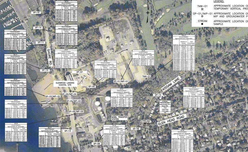
ABSTRACT

       An industrial site located along Hempstead Harbor on the north shore of Long

Island has exhibited groundwater contaminated with chlorinated volatile organic

compounds (VOCs). This report presents and investigates the hypothesis that the

chlorinated VOC contamination present at the industrial site is from an undefined

groundwater plume, known as the Glen Head groundwater plume, whose source is

located approximately one mile upgradient. Research methodology includes an analysis

of the geologic/hydrogeologic setting, a geochemical analysis of groundwater chemical

data collected in the study area, the development of a conceptual model exploring plume

dynamics, and a comparison of the conceptual model to a more extensively studied

chlorinated VOC groundwater plume located in a similar setting.

       The wide and deep distribution of chlorinated VOCs in the vicinity of the coastal

industrial site, as well as the consistent suite of chlorinated VOCs throughout and the

abundance of degradation products, is consistent with an upgradient source. Furthermore,

the geologic/hydrogeologic setting suggests that the chlorinated VOC contamination

detected at the coastal industrial site is from the Glen Head groundwater plume,

originating approximately one mile upgradient, as it migrates toward Hempstead Harbor.

The similarity between the Glen Head groundwater plume and the Lawrence Aviation

plume in Port Jefferson supports this conclusion. It is recommended that the Glen Head

groundwater plume be delineated, including a preliminary modeling effort to guide the

planning of the delineation.

                                          iii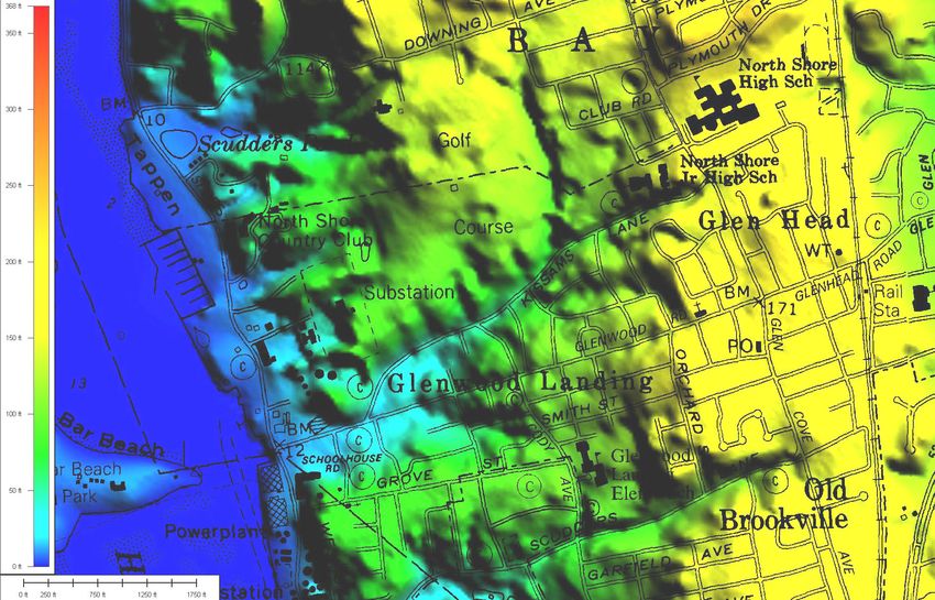
TABLE OF CONTENTS

LIST OF FIGURES ..........................................................................................................v

LIST OF TABLES ........................................................................................................... vi

PREFACE AND ACKNOWLEDGMENTS................................................................. vii

INTRODUCTION .............................................................................................................1

     Project Background .......................................................................................................1
     Approach and Methods of Research Report ..................................................................3

STUDY AREA....................................................................................................................5

     Topography ....................................................................................................................5
     Regional Geology ..........................................................................................................5
     Study Area Geologic/Hydrogeologic Setting ..............................................................10

PREVIOUS WORK.........................................................................................................17

     Upgradient Sources......................................................................................................17
     Investigation of Groundwater Quality at Coastal Site .................................................22

RESULTS - GEOCHEMISTRY ....................................................................................29

     Fate and Transport of Chlorinated VOCs in Groundwater..........................................29
     Analysis of the Site-Specific Data ...............................................................................33

RESULTS - CONCEPTUAL MODEL..........................................................................36

DISCUSSION - COMPARISON TO LAWRENCE AVIATION ...............................43

CONCLUSIONS AND RECOMMENDATIONS.........................................................48

REFERENCE LIST.........................................................................................................52

                                                                iv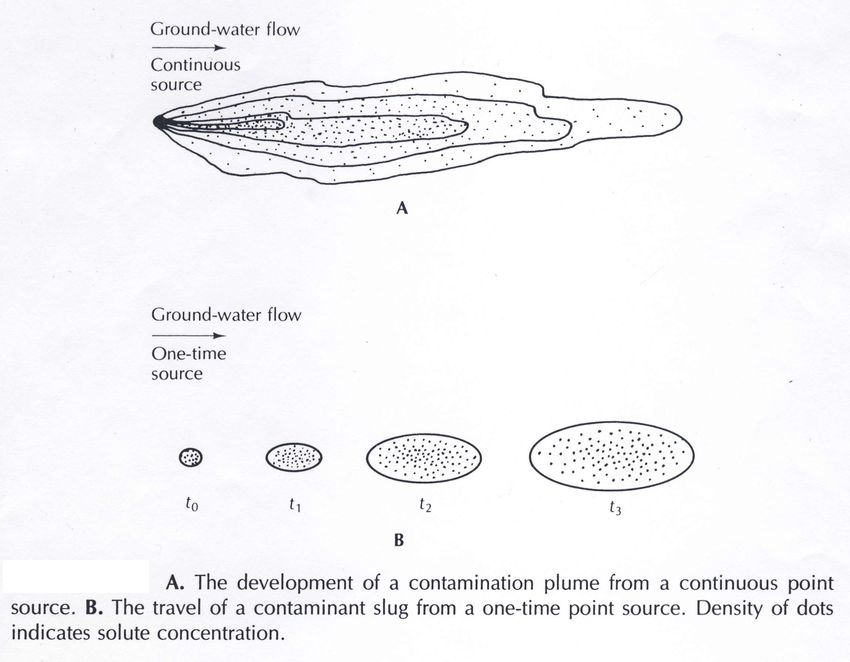
LIST OF FIGURES

Figure 1: Location of Coastal Site, adapted from D&B (2005). Depicts location of
       coastal site on a regional scale ................................................................................ 2
Figure 2: Digital Elevation Model (DEM) of Long Island indicating the location of the
       study area. DEM obtained through the website entitled, “Glacial Geology of the
       Stony Brook-Setauket-Port Jefferson Area” by Hanson......................................... 6
Figure 3: “Close-up” DEM of the study area. DEM obtained through the website
       entitled, “Glacial Geology of the Stony Brook-Setauket-Port Jefferson Area” by
       Hanson .................................................................................................................... 7
Figure 4: Cross-section Key Map Depicting Location of Coastal Site, excerpted from
       Stumm et al. (2004). As indicated, the coastal site is located close to cross-
       section B-B’ ............................................................................................................11
Figure 5: Generalized Geologic Cross-Section Depicting Coastal Site and Upgradient
       Areas, excerpted from Stumm et al. (2004). Depicts general geology in the
       study area. The approximate location of the coastal site is indicated on the
       figure .......................................................................................................................12
Figure 6: North-South Cross-Section Through Eastern Portion of Coastal Site. Cross-
       section summarizing geology and groundwater data collected by D&B along the
       eastern portion of the coastal site. Adapted from D&B (2008) ..............................14
Figure 7: Water Table Contour Map for Study Area. Map generated utilizing Nassau
       County groundwater elevations (NCDPW, 2005) ..................................................16
Figure 8: Location of Identified Upgradient Sources. Depicts locations of upgradient
       groundwater contamination sources in relation to the coastal site. Based on
       information from D&B (2005)................................................................................19
Figure 9: Sample Location Map. Groundwater sample locations completed by D&B in
       and around the coastal site. Adapted from D&B (2008) ........................................23
Figure 10: Summary of Total Chlorinated VOC Concentrations. Groundwater data for
       sample locations completed by D&B in and around the coastal site. Adapted
       from D&B (2008) ...................................................................................................26
Figure 11: North-South Cross-Section Along Shore Road. Cross-section summarizing
       geology and groundwater data collected by D&B along Shore Road in the
       vicinity of the coastal site. Adapted from D&B (2008)..........................................28
Figure 12: General schematic of a groundwater contamination plume versus a
       contaminant slug (Fetter, 1994) ..............................................................................31
Figure 13: Estimated Extent of Glen Head Groundwater Plume. Estimated lateral extent
       of the groundwater plume based on Figure 7 and groundwater quality data..........37
Figure 14: Conceptual Model of Glen Head Groundwater Plume Migration from Source
       Area to Discharge Area. Cross-section model of plume based on water quality
       data, geochemical analysis and geologic/hydrogeologic setting. Adapted from
       D&B (2008) ............................................................................................................38
Figure 15: Conceptual Model for Lawrence Aviation Site. Cross-section model of
       plume, excerpted from CDM (2006) ......................................................................45

                                                                  v
LIST OF TABLES
Table 1: Generalized Description of Hydrogeologic Units. General descriptions of
geologic units that are regionally present in the study area. Excerpted from
Stumm et al. (2004)................................................................................................. 9
Table 2: Comparison of Chlorinated VOC Concentration Ranges Between Upgradient
and Downgradient Areas. Table compares concentration ranges for different
compounds, as well as for total chlorinated VOCs. Adapted from D&B (2008) ...34
viPREFACE AND ACKNOWLEDGMENTS
The following report concerns a project I have worked on since 2005 in a
professional capacity for Dvirka and Bartilucci Consulting Engineers (D&B). Some of
the investigative and analytical work described herein was previously completed by me
and my coworkers in this time period. These efforts have been described in two reports
(D&B, 2005 and D&B, 2008). For this report, I have reviewed and interpreted previously
completed work, as well as conducted substantial additional analysis and research into
the geology/hydrogeology, geochemistry and plume dynamics. A detailed description of
the work previously completed and the work completed for this report is provided in the
Introduction.
I would like to thank all of my coworkers at D&B who contributed to this project.
Most especially I would like to thank the project manager, Tom Fox, whose guidance has
been invaluable in this project and in my career. I would also like to thank the client who
sponsored this work over the years. In return for maintaining confidentiality for this
active project, they have graciously provided permission for me to further study this issue
and publish this report. Finally, I would like to thank my advisor, Professor Gil Hanson,
for his guidance and encouragement during this process.INTRODUCTION
Project Background
In 2005, Dvirka and Bartilucci Consulting Engineers (D&B) was retained by the
owner of an industrial site located in the Village of Glenwood Landing, New York, to
determine the source of chlorinated volatile organic compound (VOC) contamination
detected in groundwater along the waterfront of the site. By request, the name and owner
of the site have been omitted for confidentiality. The site, herein also referred to as the
coastal site, is located on the north shore of Long Island and includes waterfront on
Hempstead Harbor. Figure 1, adapted from D&B (2005), depicts the location of the site
and study area. The author has been involved in this project in a professional capacity for
D&B since 2005.
By request of the site owner, specific details regarding the current and past use of
the site are confidential. However, according to records provided by the site owner, the
history of the site does not indicate that chlorinated VOCs have been used or stored.
Furthermore, as detailed below in the Previous Work section of this report, shallow
groundwater at the site collected from the water table at a depth of approximately 10 feet
below ground surface (bgs) exhibited the lowest chlorinated VOC concentrations,
whereas deeper groundwater (deeper than 50 feet bgs) exhibited the highest
concentrations (Vanasse Hangen Brustlin [VHB], 2001). If the source were located at the
site, then it is likely that shallow groundwater would be more contaminated than deeper
1N
FIGURE 1 - Location of Coastal Site. Glenwood Landing, New York. Depicts location of coastal site on a regional scale.
Adapted from D&B (2005). Scale: 1”=3000’groundwater. Based on these factors, one can hypothesize that the source of the
chlorinated VOC contamination is upgradient of the site and not from the site itself.
Approach and Methods of Research Report
This research report will confirm the veracity of the above hypothesis.
Specifically, the report will demonstrate that an undefined chlorinated VOC groundwater
plume, which is known as the Glen Head groundwater plume, is resulting in groundwater
contamination along the coastline of Glenwood Landing as it discharges to Hempstead
Harbor, including at the coastal site.
Included in this report will be a review and interpretation of previous work
conducted by others regarding potential upgradient chlorinated VOC sources, as well as
groundwater quality investigations completed in the study area. Some of this previous
work was completed by the author in a professional capacity for D&B as part of the
project team, and was described in two reports (D&B, 2005 and D&B, 2008). The work
completed for D&B included a groundwater quality investigation at and in the vicinity of
the coastal site, and the development of a preliminary conceptual model for the undefined
chlorinated VOC plume. For this research report, the following additional work will be
completed:
3• A description and analysis of the geologic/hydrogeologic setting utilizing data
collected by others, including data collected by the author for D&B. The analysis
will be enhanced by a detailed discussion of pertinent regional and glacial
geology.
• The development of a groundwater contour map utilizing a denser distribution of
monitoring wells than has been previously utilized by others. As a result, a more
accurate groundwater flow regime will be developed.
• A geochemical analysis of groundwater chemical data collected by others in the
study area, including data collected by the author for D&B. The analysis will be
enhanced by a detailed discussion of the general fate and transport of chlorinated
VOCs in groundwater.
• The preliminary conceptual model of the undefined chlorinated VOC plume
previously developed by the author for D&B as part of the project team will be
further developed and refined based on additional analysis.
• The further development of the conceptual model will include the development
of a plan view plume map for the undefined chlorinated VOC plume.
• A comparison of the conceptual model of the undefined plume to a delineated
plume that has been studied extensively and occurs in a similar north shore
geologic/hydrogeologic setting, specifically the Lawrence Aviation plume in Port
Jefferson, NY.
The development of a robust conceptual model for the undefined chlorinated
VOC groundwater plume that explains the observed contamination will be a key element
to this research report. A major challenge in developing the conceptual model will be the
relatively limited information regarding the contaminant loading history and incomplete
hydrogeologic and groundwater quality data specific to the study area. As a result, the
conceptual model will be subject to significant uncertainty. Accordingly, comparative
analysis with the similar yet more extensively studied Lawrence Aviation plume should
prove to be particularly useful.
4STUDY AREA
Topography
Two lines of hills extend along the northern and central portions of Long Island,
namely the Harbor Hill and Ronkonkoma glacial moraines, respectively. The moraines
converge in western Long Island, just south of the study area. A high-resolution digital
elevation model (DEM) of Long Island, which depicts the moraines and the location of
the study area, is provided as Figure 2. A “close-up” DEM of the study area is provided
as Figure 3. The DEMs were obtained through Hanson (2000). As depicted in Figure 3,
the topography rises steeply from west to east, with the coastal site itself rising from sea
level to an elevation of more than 80 feet in this direction. The topography continues to
rise further east, with an elevation of more than 150 feet approximately 1 mile to the east.
Figure 3 also depicts the location of identified upgradient contamination sources located
in this area, which will be described in the Previous Work section of this report.
Regional Geology
Regional geology has been developed with assistance from a number of sources,
most notably Stumm et al. (2004), but also CDM (2006), Franke et al. (1972) and
Smolensky et al. (1989), as well as Hanson (2000), and Mulch and Hanson (2004). The
study area is underlain by unconsolidated Pleistocene-aged glacial deposits above
Cretaceous-aged Coastal-Plain deposits. All of these deposits are underlain by relatively
5Study Area FIGURE 2 - Digital Elevation Model (DEM) of Long Island indicating the location of the study area. DEM obtained through the website entitiled, “Glacial Geology of the Stony Brook-Setauket-Port Jefferson Area” by Hanson.
N

                                                                                                                                                     TransTechnology

                                                                                                                                             n
                                                                                                                                          Gle rs
                                                                                                                                  o r mer leane
                                                                                                                                 F ad C
                                                                                                                                  He

             Site Location
                                                                                                                                             er
                                                                                                                                        Form h&
                                                                                                                                         Fresan
                                                                                                                               dview      Cle ndry
                                                                                                                       Soun ners          Lau
                                                                                                                        C l e a

FIGURE 3 - “Close-up” DEM of the Study Area. Location of coastal site and upgradient contamination sources are indicated.
            DEM obtained through the website entitiled, “Glacial Geology of the Stony Brook-Setauket-Port Jefferson Area” by Hanson.
impermeable crystalline bedrock of early Paleozoic age. A generalized description of the
various deposits that have been identified in the study area is provided in Table 1,
excerpted from Stumm et al. (2004).
The Raritan Formation of Cretaceous age overlies the bedrock, and consists of the
Lloyd aquifer and the overlying Raritan Clay confining unit. The Lloyd aquifer consists
of white-to-gray, fine-to-coarse sand and gravel, commonly with a clayey matrix. The
Raritan Clay is solid clay with multicolors, including gray, white, red or tan. The
Cretaceous-aged Magothy aquifer overlies the Raritan Formation, and consists of
interbedded fine-to-medium sand, silt and clay.
Subsequent glaciations resulted in glacial erosion of the Cretaceous deposits.
Therefore, the top of the Cretaceous sequence consists of a highly irregular erosional
surface, above which lies Pleistocene-aged deposits. In some areas of the region, this
erosion has resulted in the removal of all of the Cretaceous deposits down to the bedrock.
These glacial advances carved low-lying valleys (tunnel valleys) that were later filled by
moderately permeable outwash deposits and capped by as much as hundreds of feet of
clay and silt, possibly originating from temporary glacial lakes. These filled valley
deposits constitute the North Shore aquifer and North Shore confining unit, as designated
in Stumm et al. (2004).
The uppermost unit in the study area consists of the glacial till and outwash
deposits of the Pleistocene-aged Upper Glacial aquifer. It consists mainly of poorly-to-
8TABLE 1 - General descriptions of geologic units that are regionally present in the study area. Excerpted from Stumm et al. (2004).
moderately sorted fine-to-coarse sand and gravel with variable amounts of clay and silt,

and is considered to have excellent water transmitting properties. In some areas,

Cretaceous deposits have been thrust upward by glaciotectonics (ice shove) and

incorporated into the Upper Glacial aquifer.

Study Area Geologic/Hydrogeologic Setting

       A key map and associated hydrogeologic cross-section, adapted from Stumm et

al. (2004), are provided as Figure 4 and Figure 5, respectively. As depicted in Figure 4,

cross-section B-B’ runs from Hempstead Harbor (in the approximate location of the

coastal site) to upgradient areas to the east. As depicted in Figure 5, the study area is

immediately underlain by the Upper Glacial aquifer with a thickness of approximately

225 feet. Regionally, the Upper Glacial aquifer generally overlies the Magothy aquifer.

However, it appears that the Magothy aquifer has been completely eroded away in the

majority of the study area and, as a result, the Upper Glacial aquifer directly overlies the

Raritan Clay confining unit. The Raritan Clay beneath the study area appears to consist of

solid, compact clay at least 100 feet thick and, therefore, acts effectively as a confining

unit preventing the vertical migration of chemical constituents.

       Soil boring logs were also examined from the study area for this report, and

included soil borings completed on the coastal site (VHB, 2001 and D&B, 2008), Nassau

County observation well logs scattered throughout the study area and soil borings

completed in upgradient areas to the east (Lawler, Matusky & Skelly Engineers [LMS],

                                            10
N
Approximate Site Location
SOURCE: USGS WATER RESOURCES INVESTIGATIONS REPORT 03-4288
FIGURE 4 - Cross-Section Key Map Depicting Location of Coastal Site. As indicated, the coastal site is
located close to cross-section B-B’. Excerpted from Stumm et al. (2004). Apprx Scale: 1”=1.25MIFIGURE 5 - Generalized Geologic Cross-Section Depicting Coastal Site and Upgradient Areas.
Depicts general geology in the study area. The approximate location of the coastal site is indicated. Excerpted from Stumm et al. (2004)2000 and Environmental Resources Management [ERM], 2007). In addition, a north-
south geologic cross-section completed along the eastern portion of the coastal site is
provided as Figure 6 (adapted from D&B, 2008). The available geologic data generally
corroborate the geologic setting presented above. The glacial sediments seem to consist
of fine-to-medium sand with varying amounts of silt and gravel, with fairly good water
transmitting properties. However, the available information also indicates that there exist
numerous low-permeable clay-rich zones or lenses interbedded in the Upper Glacial
aquifer. These lenses seem generally to be discontinuous and thin, extending no more
than 10 to 20 feet in thickness, and may be glacial sediments or Cretaceous deposits that
have been thrust upward by ice shove. The presence of these lenses may limit the
vertical flow of groundwater, as well as the vertical migration of contaminants.
The soil borings do not indicate evidence that the Cretaceous-aged Magothy
aquifer is present in a significant way beneath the study area. In fact, as depicted in
Figure 6, borings N-4462/N-9800 and TMW-01 exhibited evidence that the Upper
Glacial aquifer transitions directly to solid clay of the Raritan confining unit at a depth of
approximately 270 feet.
The water table is present within the Upper Glacial aquifer throughout the study
area, and is found at depths as shallow as 6 feet or less adjacent to Hempstead Harbor,
and as deep as 115 feet in upgradient areas approximately 1 mile to the east (D&B,
2008). Utilizing existing Nassau County observation wells screened at the water table and
depth to water readings obtained by Nassau County (NCDPW, 2005), a water table
13ELEVATION IN FEET RELATIVE TO MEAN SEA LEVEL
HORIZONTAL SCALE: 1” = 300’
FIGURE 6 - North-South Cross-Section Through Eastern Portion of Coastal Site. Cross-section summarizing geology and groundwater data collected by D&B along the eastern portion of the coastal site. Adapted from D&B (2008).contour map has been plotted on a USGS topographic map for this report and provided as
Figure 7. The figure depicts the location of identified upgradient contamination sources,
which will be described in the Previous Work section of this report. As depicted in
Figure 7, horizontal groundwater flow is westward from upgradient areas toward
Hempstead Harbor and the coastal site. Note that the gradient in the water table matches
the topography, in that it is relatively shallow in the eastern portion but steepens rapidly
approaching Hempstead Harbor.
According to Stumm et al. (2004), there is a moderate-to-strong downward
vertical gradient in groundwater flow in upgradient areas located to the east of the coastal
site, indicating an area of groundwater recharge. This would promote the vertical
migration of chlorinated VOC contaminants into deeper zones of the Upper Glacial
aquifer. By contrast, measurements of hydraulic head on the coastal site adjacent to
Hempstead Harbor indicate a strong upward vertical gradient in groundwater flow (D&B,
2008). This would indicate that Hempstead Harbor, which appears to have been formed
as a tunnel valley during the last glaciation, serves as an area of groundwater discharge.
1510 20
N 30 40
N-11777
13.22
N-11795
41.78 50
TransTechnology
N-9800
22
MW-8 MW-1
49 51
Former Glen
Head Cleaners
Site Location
Former
Fresh &
Soundview Clean
Cleaners Laundry
N-11778
42.31
FIGURE 7 - Water Table Contour Map for Study Area. Map generated utilizing Nassau County groundwater elevations (NCDPW, 2005). Approximate Scale: 1”=650’. Note: elevations relative to mean sea level. Well N-10245 located off map to the east with water elevation of 53.82 also used for contouring.PREVIOUS WORK
Upgradient Sources
As mentioned in the Introduction, groundwater at the waterfront parcel of the
coastal site has previously been found to be contaminated with chlorinated VOCs (VHB,
2001). Specifically, a previous investigation commissioned by the site owner and
completed in 1999 (VHB, 2001), found that tetrachloroethene (PCE) was the most
frequently detected chlorinated VOC, with concentrations detected as high as 820
micrograms per liter (µg/l) or parts per billion (ppb). Other chlorinated VOCs that were
detected included trichloroethene (TCE), 1,2-dichloroethene (1,2-DCE), 1,1,1-
trichloroethane (TCA) and 1,1-dichloroethane (1,1-DCA) (VHB, 2001).
As discussed earlier, there is no evidence for a source of chlorinated VOCs at the
coastal site according to records provided by the site owner. The chlorinated VOCs
detected, particularly PCE, TCE and TCA, are widely used in numerous commercial and
industry applications, none of which have occurred at the site (D&B, 2005). PCE, which
was the most frequently detected compound, is widely used in dry cleaning operations.
As summarized in D&B (2005), a review of federal, state and local records was
conducted to identify potential upgradient sources for the groundwater contamination
observed at the coastal site. Records reviewed generally included correspondence from
regulatory agencies and reports documenting completed groundwater sampling (D&B,
172005). Groundwater flow is generally from east to west toward Hempstead Harbor in the
study area. Therefore, areas to the east are considered upgradient.
The record review identified four potential chlorinated VOC sources, including an
electronics manufacturer (TransTechnology) and three dry cleaning businesses, located
approximately 1 mile east and potentially upgradient of the coastal site (D&B, 2005). The
locations of the four identified upgradient sources are depicted in Figure 8. The
following, summarized from D&B (2005), presents a brief description of the available
records for each source, as well as for the collective source area, referred to as the Glen
Head groundwater plume.
• TransTechnology Corporation
As depicted in Figure 8, the TransTechnology site is located approximately 1
mile to the east of the coastal site. Lundy Electronics Company formerly occupied the
site, where it operated a machine shop and manufactured electronics (D&B, 2005).
TransTechnology acquired Lundy in the early 1980s, and assembled electronic
components until 1994 (D&B, 2005). Correspondence from 1977 indicates that cleaning
solvents were being improperly disposed of in the site’s cesspool (D&B, 2005). Beyond
this information, specific time periods or dates when contaminants were released to the
subsurface are not known.
18N
TransTechnology
Former Glen
Head Cleaners
Former Fresh &
Clean Laundry
Soundview
Cleaners
FIGURE 8 - Location of Identified Upgradient Sources. Glenwood Landing, New York. Depicts location of upgradient groundwater contamination sources in
relation to the coastal site. Based on information from D&B (2005). Scale: 1”=3000’Analytical results from the cesspool found TCA concentrations as high as 100,000
µg/l (D&B, 2005). Numerous site investigations conducted in the 1990s found elevated
concentrations of chlorinated VOCs in on-site groundwater collected at the water table at
a depth of approximately 115 feet bgs, with maximum PCE and TCE concentrations of
16,000 µg/l and 3,300 µg/l, respectively (D&B, 2005). Deeper groundwater data are
limited, but found TCE concentrations as high as 3,600 µg/l (D&B, 2005).
• Dry Cleaning Businesses
The former Fresh and Clean Laundry site is located approximately 850 feet
southeast of the TransTechnology site. This dry cleaner site is a State Hazardous Waste
Site, which, according to the state’s database, “appears to be the primary contributor to
the PCE contamination” in the area of the TransTechnology site (D&B, 2005).
Correspondence from 1980 indicates that wastewater containing PCE was being illegally
disposed of onto the surface of the ground and into septic tank systems and cesspools
(D&B, 2005). This site was reportedly a dry cleaner until 1988 (D&B, 2005). Other dry
cleaners in the area, including Soundview Cleaners and Glen Head Cleaners, were
documented as illegally discharging dry cleaning fluids to the ground, either directly or to
cesspools (D&B, 2005). Beyond this information, specific time periods or dates when
contaminants were released to the subsurface are not known.
20• Glen Head Groundwater Plume
As depicted in Figure 8, all of the potential source areas are located within 1,200
feet of each other near the Long Island Railroad (LIRR) right-of-way, and approximately
1 mile east and potentially upgradient of the coastal site. Due to the dense concentrations
of source areas and overall elevated concentrations of chlorinated VOCs detected in
groundwater, the New York State Department of Environmental Conservation
(NYSDEC), a state environmental regulatory agency, has attempted to investigate the
source area as a whole, referring to the project as the “Glen Head groundwater plume”
(LMS, 2000). The NYSDEC efforts have included two investigations of the source area,
including a Preliminary Site Assessment (PSA) conducted in 1999 and 2000 (LMS,
2000), and a Site Characterization conducted in 2005 and 2006 (ERM, 2007).
The PSA included sampling of shallow groundwater in the source area, including
from 11 shallow monitoring wells and four groundwater probes (LMS, 2000).
Groundwater samples were collected at or just below the water table at a depth of
approximately 115 feet bgs, although some samples were collected as deep as 160 feet
bgs (LMS, 2000). Elevated concentrations of chlorinated VOCs were detected throughout
the source area. However, PCE was detected at concentrations significantly higher than
other chlorinated VOCs, with a maximum concentration of 18,000 µg/l (LMS, 2000). No
other chlorinated VOC was detected higher than 130 µg/l, suggesting that PCE was the
dominant chlorinated VOC discharged in this area (LMS, 2000).
21The Site Characterization included sampling of the existing monitoring well
networks in the Glen Head groundwater plume source area (ERM, 2007). Elevated
concentrations were again detected in shallow groundwater throughout the area, with
PCE being the dominant compound detected (ERM, 2007). Given that additional
sampling points were not installed, the report concluded that the sampling “…confirmed
the existence and configuration of the Glen Head groundwater plume”, while noting that
the limits of the plume are not adequately delineated (ERM, 2007).
Given the extensive groundwater contamination and a groundwater flow direction
to the west, it is apparent that the Glen Head groundwater plume could be the source of
the contamination observed at the coastal site located on Hempstead Harbor. However,
based on the above discussion, the specific contaminant loading history is not completely
known. Although the operations that resulted in the release of contaminants to the
subsurface ceased some 20 to 30 years ago, it is not clear when such operations were
initiated. Based on the types of operations involved, it is suspected that the contaminants
were released neither during one specific event nor continuously, but rather intermittently
when sufficient volumes of waste accumulated to the point where disposal was required.
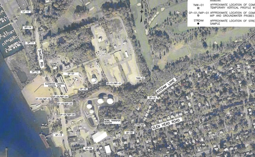
Investigation of Groundwater Quality at Coastal Site
In 2006 and 2007, additional groundwater and surface water samples were
collected in and around the coastal site by D&B on behalf of the site owner in order to
help determine the source of the contamination (D&B, 2008). Sample locations are
depicted in Figure 9, adapted from D&B (2008). A total of 15 groundwater probes (GP-
22FIGURE 9 - Sample Location Map. Groundwater sample locations completed by D&B in and around the coastal site. Adapted from D&B (2008). Scale: 1”=250’
01 through GP-15) were completed in and around the site, with multiple groundwater

samples collected at different depths from each probe (D&B, 2008). Each probe included

at least one sample collected at the water table, located at approximately 10 feet bgs

along the western downgradient portion of the coastal site, and one at the maximum

depth of the probe, which ranged from 94 feet to 132 feet depending on subsurface

conditions (D&B, 2008). In addition, a temporary vertical profile well was completed and

a surface water stream sample was collected (D&B, 2008). The following description of

the field program, as well as the total chlorinated VOC results, is summarized from D&B

(2008).

          As depicted in Figure 9, groundwater probes GP-01 and GP-02 were completed

east of Shore Road as part of the first phase of sample collection. GP-03 was completed

within the historically contaminated parcel for comparison purposes. GP-04 through GP-

07 were completed along Shore Road, while GP-08 through GP-10 were completed

southeast of the coastal site. GP-11 through GP-15 were also completed along Shore

Road, including further north and south of the site in order to delineate the width of the

chlorinated VOC contamination.

          Groundwater samples were collected using Geoprobe technology by driving rods

to each designated sample depth and retracting 4 feet to expose a decontaminated

stainless steel screen. Dedicated tubing and a peristaltic pump were used to purge

groundwater and collect samples for laboratory analysis of VOCs. Membrane Interface

Probes (MIPs) were utilized to target sampling depths at a number of the groundwater

                                           24
probe locations. MIPs are advanced using standard Geoprobe equipment and include
multiple sensors, such as an electron capture detector (ECD). The ECD can detect the
relative concentrations of chlorinated VOCs over depth.
In addition, a temporary vertical profile well (TMW-01) was completed on the
elevated easternmost portion of the coastal site, which consisted of a soil boring
completed by the hollow stem auger drilling method. To determine stratigraphy, soil
samples were collected during installation and gamma logging was completed. The well
was completed to a depth of 291 feet where a substantial clay confining unit was
encountered, assumed to be the Raritan Clay. A total of 16 groundwater samples were
collected for VOC analysis from the boring by installing a temporary well into the
borehole and using a submersible pump to purge and collect groundwater, with the
shallowest sample collected from the water table. On this elevated portion of the coastal
site, the water table is located approximately 60 feet bgs.
Figure 10 summarizes the total chlorinated VOC concentration for each sample
collected (adapted from D&B, 2008). Note that the depth and elevation of each sample is
also depicted, relative to mean sea level. As depicted in Figure 10 and consistent with
previous investigations on the contaminated parcel, GP-03 exhibited the highest
chlorinated VOC concentrations at depths between 46 and 94 feet below grade, with total
chlorinated VOC concentrations as high as 1,166 µg/l. Elevated concentrations of
chlorinated VOCs were also detected in all probes completed along Shore Road,
including as far south as GP-13 and as far north as GP-15, with a maximum total
chlorinated VOC concentration of 1,346 µg/l detected in sample GP-11 (54 to 58 feet).
25FIGURE 10 - Summary of Total Chlorinated VOC Concentrations. Groundwater data for sample locations completed by D&B in and around the coastal site. Adapted from D&B (2008). Approximate Scale: 1”=250’
Figure 11 presents a north-south cross-section along Shore Road summarizing chemical

data (adapted from D&B, 2008). Trace concentrations of chlorinated VOCs were

detected south and east of the site at GP-01, GP-02, GP-08 through GP-10 and TMW-01.

       Based on data presented in the NYSDEC’s Site Characterization of the Glen Head

groundwater plume (ERM, 2007), a surface water sample collected from a natural

groundwater spring located approximately 1,000 feet north of GP-15 on the North Shore

Country Club golf course exhibited a PCE concentration of 130 µg/l. This makes the

contaminant plume a minimum of 2,800 feet wide, a distance of more than half a mile.

       Further examination of the data along Shore Road finds that the contamination

appears to be deeper south and inland from the site, and progressively shallower to the

north where surface water bodies such as ponds and creeks are present. These data

support the idea of a deep plume discharging to surface water bodies such as Hempstead

Harbor, as well as ponds and creeks in the area. The conceptual model of the plume will

be presented later in this report. However, such a wide and deep plume, along with trace

concentrations detected in some inland areas, is likely the result of the multiple source

areas associated with a degraded Glen Head groundwater plume and not from a single

source located along the coast.

                                           27
ELEVATION IN FEET RELATIVE TO MEAN SEA LEVEL
HORIZONTAL SCALE: 1” = 300’
FIGURE 11 - North-South Cross-Section Along Shore Road. Cross-section summarizing geology and groundwater data collected by D&B along Shore Road in the vicinity of the coastal site. Adapted from D&B (2008).RESULTS - GEOCHEMISTRY
Fate and Transport of Chlorinated VOCs in Groundwater
Chlorinated VOCs, including PCE, are denser than water (Montgomery et al.,
1990). Accordingly, chlorinated VOCs can behave as dense nonaqueous phase liquids
(DNAPLs) when released into the subsurface and prior to dissolving into the
groundwater. As discussed earlier, previous NYSDEC investigations of the Glen Head
groundwater plume source area identified dissolved PCE concentrations up to 18,000
µg/l. This concentration is approximately 6% of the maximum pure phase solubility of
PCE in water at 20 degrees Celsius (Montgomery et al., 1990). USEPA (1992) has
determined that DNAPLs are likely present when contaminant concentrations in
groundwater are greater than 1% of the contaminant’s pure phase solubility. Therefore,
the high chlorinated VOC concentrations detected in groundwater in the source area are a
likely indication that contaminants were released in sufficient quantities to reach the
aquifer as DNAPLs. The conceptual model will be discussed later in this report.
However, it is likely that accumulated DNAPL in the aquifer has served as a long-term
source of dissolved chlorinated VOC contamination.
As with other contaminants, once chlorinated VOCs are dissolved in groundwater,
they will migrate with the groundwater in the direction of groundwater flow as a
contaminant plume through advection. During this migration, the concentration of
chlorinated VOCs is subject to natural attenuation processes, including:
29• Dispersion and Diffusion
• Adsorption
• Volatilization
• Biodegradation
As contaminated groundwater flows, it will mix with relatively uncontaminated
groundwater as a consequence of variations in groundwater velocity and the aquifer’s
matrix (CDM, 2006 and Fetter, 1994). The dilution of the contaminant concentration that
occurs is described as mechanical dispersion (Fetter, 1994). Diffusion results from
movement of dissolved contaminants from zones of high concentration to zones of low
concentration. Therefore, diffusion is dependent on concentration gradients (CDM,
2006). Dispersion and diffusion result in a spreading out of the contaminant beyond the
average groundwater flow path that would be described by advection alone, as well as a
decrease in the concentration of the contaminant with further distance from the source. In
addition, the contaminant will spread in the direction of groundwater flow more than in
the direction perpendicular to groundwater flow (Fetter, 1994). Therefore, a continuous
source will result in a groundwater contaminant plume while a one-time or intermittent
spill will result in a contaminant slug (Fetter, 1994). A diagram of these scenarios,
excerpted from Fetter (1994), is provided as Figure 12.
Dissolved contaminants typically migrate slower than the groundwater in which
they are dissolved due to interaction with solids in the aquifer. These interactions,
primarily adsorption onto solids, remove the contaminant from the groundwater and
30FIGURE 12 - General schematic of a groundwater contamination plume versus a contaminant slug (Fetter, 1994).
retard its movement in groundwater (CDM, 2006). For VOCs, the amount of organic

carbon present in the aquifer is important in determining the amount of adsorption that is

occurring (CDM, 2006). In addition, volatile compounds such as chlorinated VOCs will

volatilize off of the groundwater and into the unsaturated zone above the water table.

Both adsorption and volatilization decrease overall contaminant concentrations in

groundwater.

         Perhaps the most important mechanism of natural attenuation for chlorinated

VOCs in groundwater is biodegradation, specifically reductive dechlorination (USEPA,

1998). Reductive dechlorination is the process by which chlorinated compounds are

progressively dechlorinated, assuming the presence of sufficient bacteria and electron

donors, such as anthropogenic or natural organic carbon (CDM, 2006 and USEPA, 1998).

During the process, the chlorinated hydrocarbon is used as an electron acceptor, and

chlorine atoms are progressively replaced by hydrogen, resulting in compounds with less

chlorine (CDM, 2006 and USEPA, 1998). In general, reductive dechlorination tends to

proceed as follows (CDM, 2006; Chapelle, 1993 and USEPA, 1998):

PCE (C2Cl4) Æ TCE (C2HCl3) Æ 1,2-DCE (C2H2Cl2) Æ vinyl chloride (C2H3Cl) Æ
ethene (C2H4) Æ CO2

         Reductive dechlorination tends to result in the accumulation of daughter products.

As discussed below, the detection of significant concentrations of TCE and 1,2-DCE in

groundwater is associated with the downgradient areas of the Glen Head groundwater

plume.

                                             32
Analysis of the Site-Specific Data
A closer examination of the geochemistry of the available groundwater data
provides further evidence that an upgradient groundwater source is responsible for the
groundwater contamination observed along the coast. For example, all of the chlorinated
VOCs identified downgradient along the coast were also detected in the upgradient
source areas (i.e. the TransTechnology site and the Glen Head groundwater plume).
Table 2, adapted from D&B (2008), presents a comparison of chlorinated VOC
concentration ranges for specific compounds between the upgradient and downgradient
areas. As indicated in Table 2, PCE is the predominant compound detected at both
upgradient and downgradient areas, though overall concentrations of PCE downgradient
are lower than those detected upgradient. The higher concentrations of PCE in the
upgradient areas are indicative of samples collected within or immediately downgradient
of the contamination source area. The lower concentrations of PCE in the downgradient
areas likely represent the naturally attenuated lower limits of the resulting Glen Head
groundwater plume as it discharges to Hempstead Harbor (D&B, 2008).
The overall concentrations of TCE and 1,2-DCE detected in downgradient areas
are also generally lower than upgradient areas. However, when compared to PCE, they
are present at relatively greater concentrations in downgradient areas. As discussed
earlier, TCE and 1,2-DCE are degradation products of PCE. Their greater relative
concentrations in downgradient areas, when compared to PCE, indicate that reductive
33TABLE 2 - Comparison Of Chlorinated VOC Concentration Ranges Between Upgradient and
Downgradient Areas. Table compares concentration ranges for different compounds, as well as for total
chlorinated VOCs. Adapted from D&B (2008).
Upgradient
Upgradient
Groundwater 2001/2003 Coastal Site 2006/2007 Coastal Site
Groundwater
Compound Concentration Range - Groundwater Groundwater
Concentration Range -
Glen Head 2 Concentration Range 3 Concentration Range 4
TransTechnology
Groundwater Plume 1
PCE ND - 18,000 ND - 16,000 ND - 1,700 ND - 1,230
TCE ND - 130 ND - 1,800 ND - 270 ND - 430
1,2 - DCE ND - 130 ND - 310 ND - 180 ND - 74
TCA ND - 4 ND - 41 ND - 7 ND - 6
1,1 - DCA ND - 1 ND - 15 ND - 10 ND - 6
Total
Chlorinated 3 - 18,192 ND - 16,252 ND - 2,167 ND - 1,346
VOCs
Notes:
All concentrations in ug/l.
1
: From September 2000 Glen Head Groundwater Plume PSA Report by
LMS and February 2007 Glen Head Groundwater Plume Site
y Report by ERM gy
Characterization g y
February 2007 Glen Head Groundwater Plume Site Characterization Report
by ERM.
3
: From September 2001 Supplemental Environmental Site Assessment and
October 2003 Supplemental Environmental Sampling Report by VHB
4
: From 2006, 2007 Groundwater Investigation by D&B
1 of 1dechlorination has occurred as the contaminant plume has migrated through the aquifer
(D&B, 2008).
As noted earlier, vinyl chloride and ethene are also daughter products produced
during reductive dechlorination. Vinyl chloride was not detected in downgradient areas,
while ethene was not analyzed for during the various investigations. As discussed in
USEPA (1998), vinyl chloride may not accumulate in downgradient portions of plumes
where aerobic conditions promote the oxidation of vinyl chloride to carbon dioxide.
As discussed earlier, chlorinated VOCs were detected along the coast, both north
and south of the coastal site, for a minimum width of 2,800 feet, a distance of more than
half a mile. The data indicate the presence of a very consistent suite of chlorinated VOCs
throughout this plume width, with all groundwater probes exhibiting the presence of
PCE, TCE, 1,2-DCE, TCA and 1,1-DCA. Additionally, the relative concentrations of
these compounds are consistent in the following fashion:
• PCE is the predominant compound detected.
• Degradation products TCE and 1,2-DCE are present at lower but significant
concentrations.
• Degradation products TCA and 1,1-DCA are present at trace concentrations.
This consistency over such a wide area and variety of environments (industrial
sites, country club, park, etc.) suggests a common contaminant source unrelated to the
coastal site or other nearby property.
35RESULTS - CONCEPTUAL MODEL
Utilizing the water table contour map provided as Figure 7, a plan view map
depicting the estimated maximum lateral extent of the Glen Head groundwater plume has
been developed for this report and is provided as Figure 13. In addition, Figure 14
presents a cross-section conceptual model of the Glen Head groundwater plume starting
at the upgradient source area and ending at the discharge area at Hempstead Harbor in the
vicinity of the coastal site (adapted from D&B, 2008). Note that Figure 7, Figure 13
and Figure 14 have been generated based on the totality of the information previously
presented in this report, including water quality data and historical information from the
Glen Head groundwater plume source area, water quality data from the vicinity of
Hempstead Harbor, geochemical analysis and the examination of the
geologic/hydrogeologic setting.
The following description of the conceptual model is based on the preliminary
conceptual model (D&B, 2008), and reflects the additional research performed in this
report. As discussed previously, the concentrations of chlorinated VOCs in the Glen Head
groundwater plume source area are such that it is likely that the contaminants reached the
Upper Glacial aquifer as DNAPLs. Being heavier than water, the DNAPLs continued to
migrate vertically into the deeper zones of the aquifer until an impermeable unit was
encountered or loss of volume prevented further migration. Loss of volume would occur
due to dissolving of the chlorinated VOCs from the DNAPL into the groundwater, as
well as trapping of the DNAPL in pore spaces. Figure 14 depicts the DNAPL being
3610 20
N 30 40
N-11777
13.22
N-11795
41.78 50
TransTechnology
Possible spreading Plume may be degraded/
out of plume as it intermittent along path
discharges
N-9800
22
MW-8 MW-1
49 51
Former Glen
Head Cleaners
Site Location
Former
Fresh &
Soundview Clean
Cleaners Laundry
Possible spreading
out of plume as it
discharges
N-11778
42.31
FIGURE 13 - Estimated Extent of Glen Head Groundwater Plume. Estimated lateral extent of the groundwater plume based on Figure 7 and groundwater quality data. Approximate Scale: 1”=650’. Note: elevations relative to mean sea level.ELEVATION IN FEET RELATIVE TO MEAN SEA LEVEL FIGURE 14 - Conceptual Model of Glen Head Groundwater Plume Migration From Source Area to Discharge Area. Cross-Section model of plume based on water quality data, geochemical analysis and geologic/hydrogeologic setting. Adapted from D&B (2008).
released from the source areas and migrating vertically into the saturated zone. The

vertical migration stops somewhere deep in the Upper Glacial aquifer. Left behind are

zones of immobile residual DNAPL.

       Due to the presence of DNAPL and the documented strong downward hydraulic

vertical gradient in the source area, the Glen Head groundwater plume likely tended to

migrate more vertically before migrating in a more horizontal and westerly direction with

the natural flow of groundwater. As a result, the main body of chlorinated VOC

contamination would be found in deeper zones of the aquifer downgradient of the source

area. However, lower concentrations would be detectable in more shallow zones due to

dispersion/diffusion of the plume, as well as the smaller component of horizontal

groundwater flow that occurred in these more shallow zones of the aquifer. This diffuse

zone is depicted in Figure 14.

       The zones of residual DNAPL serve as a long-term source of chlorinated VOC

contamination for the Glen Head groundwater plume. However, it is suspected that the

source of DNAPL was intermittent (i.e. not continuous nor a one-time event), and ceased

some 20 to 30 years ago. Once the source ceased, the mass of residual DNAPL began to

decrease. Therefore, it is likely that the Glen Head groundwater plume is not currently

continuous, with high chlorinated VOC concentrations within and immediately

downgradient of the source area near the residual DNAPL, and low or nondetectable

concentrations in some areas further downgradient. Furthermore, the contamination has

been degraded through natural processes such as reductive dechlorination. As discussed

                                           39
earlier, other processes, such as dispersion/diffusion, volatilization and adsorption, also
reduce concentrations of chlorinated VOCs in groundwater. As a result of these natural
processes and the fact that the DNAPL source was removed, chlorinated VOC
concentrations can be present in low or nondetectable concentrations in some areas
downgradient of the source, even in the deeper zones of the Upper Glacial aquifer. The
best example of this is the groundwater samples collected from temporary vertical profile
well TMW-01, which detected very low levels of chlorinated VOCs on the upgradient
portion of the coastal site.
As depicted in Figure 14, total chlorinated VOC concentrations are relatively
high in the vicinity of Hempstead Harbor, where the plume discharges to surface water.
Contamination associated with the Glen Head groundwater plume migrates west in
deeper zones of the Upper Glacial aquifer until reaching the area where the aquifer begins
a strong upward vertical hydraulic gradient. As discussed earlier, evidence of the upward
gradient and groundwater discharge zone was detected in the vicinity of Hempstead
Harbor. After reaching this zone, the Glen Head groundwater plume migrates almost
vertically upward and discharges to Hempstead Harbor and other surface water bodies.
The high concentrations of chlorinated VOCs detected at the coastal site and along
Hempstead Harbor represent the final remnants of the active period of the upgradient
sources, when DNAPL was still being released to the subsurface.
As depicted in Figure 11, significant groundwater contamination has been
detected over a wide area in the discharge zone. Contamination appears to extend north
40beyond groundwater probe GP-15. Based on data from the NYSDEC, a surface water
sample collected from a natural groundwater spring located approximately 1,000 feet
north of GP-15 on the North Shore Country Club golf course exhibited PCE (ERM,
2007). This makes the contaminant plume a minimum of 2,800 feet wide, a distance of
more than half a mile. As depicted in Figure 13, such a wide plume is likely the result of
the multiple source areas of the Glen Head groundwater plume. In addition, the plume
appears to spread out as it discharges. This is likely due to the presence of numerous clay
lenses in the Upper Glacial aquifer, which forces the contamination to spread out and find
the path of least resistance (i.e. around rather than through the clay lenses) as it
discharges.
Figure 13 depicts the estimated maximum lateral extent (i.e. path) of the plume,
but does not suggest that high concentrations of chlorinated VOCs are currently
detectable in groundwater throughout the depicted path of the plume. As described above,
the conceptual model of the current pattern of contamination for the plume is as follows:
• High concentrations of chlorinated VOCs in groundwater within and immediately
downgradient of the source area, reflecting the presence of residual DNAPL in the
aquifer.
• Low or nondetectable concentrations of chlorinated VOCs in groundwater in
some areas between the source and the discharge, reflecting the removal of the
source of additional DNAPL to the aquifer, the reduced mass of residual DNAPL
at the source area, and natural processes that reduce contaminant concentrations.
• High concentrations of chlorinated VOCs in groundwater at the discharge area,
reflecting the final remnants of the active period of the upgradient sources.
41This pattern of contamination observed for the Glen Head groundwater plume has
been observed in other “old” chlorinated VOCs plumes in similar hydrogeologic
environments on the north shore of Long Island, including the Lawrence Aviation
groundwater plume located in Port Jefferson, New York. Further discussion of the
similarity between the two sites is presented in the next section of this report.
42DISCUSSION - COMPARISON TO LAWRENCE AVIATION
As described earlier, the Glen Head groundwater plume exhibits elevated
concentrations of chlorinated VOCs near the source and discharge areas, with low or
nondetectable concentrations in areas in-between. This pattern has resulted from the
removal of the source of additional DNAPL, and natural processes that reduce
contaminant concentrations, such as reductive dechlorination and dispersion/diffusion. A
similar pattern, and similar conceptual model and hydrogeologic environment, is
associated with the Lawrence Aviation (LA) groundwater plume located in Port
Jefferson, New York. The information provided below concerning the LA site and
groundwater plume is compiled from the USEPA Record of Decision (USEPA, 2006)
and Final Remedial Investigation Report (CDM, 2006).
The LA site is located in the Village of Port Jefferson in a similar north shore
hydrogeologic environment as the Glen Head groundwater plume. Port Jefferson Harbor
is located approximately 1 mile to the north and downgradient of the LA site in the
direction of groundwater flow. As discussed earlier, there is a similar distance between
the Glen Head groundwater plume source area and discharge area. Also similar to Glen
Head, past improper disposal of PCE, TCE and other contaminants to the ground that
occurred mostly in the 1970s and 1980s resulted in contamination of the underlying
groundwater and the generation of a chlorinated VOC groundwater plume. Initial
downgradient investigations identified groundwater and surface water contaminated with
PCE, TCE and other daughter products.
43You can also read