Operating Manual for Table Top Centrifuge - Z 326 - HERMLE ...
←
→
Page content transcription
If your browser does not render page correctly, please read the page content below
Operating Manual for
Table Top Centrifuge
 Z 326
CONTENTS

1. PRODUCT DESCRIPTION ..................................................................................................1
 1.1 Safety Instructions ............................................................................................................................................ 1
 1.2 Intended Purpose .............................................................................................................................................. 1
 1.3 Brief Description ................................................................................................................................................ 1
 1.4 Delivery Package ............................................................................................................................................... 1
 1.5 Operating and Display Elements ...................................................................................................................... 2
 1.5.1 LCD-Display .................................................................................................................................................... 3
 1.6 Signs and Indications of the Centrifuge .......................................................................................................... 4
 1.6.1 General............................................................................................................................................................ 4
 1.6.2 Product Nameplate (Example) ........................................................................................................................ 4
 1.6.3 Warning and Information Signs ....................................................................................................................... 5
 1.6.4 Danger, Precautions and Warranty ................................................................................................................. 5
 1.6.5 Following Rules Must Strictly be Adhered To: ................................................................................................. 5
 1.6.6 Warranty .......................................................................................................................................................... 6
 1.7 Installation of the Centrifuge ............................................................................................................................ 7
 1.7.1 Unpacking the Centrifuge ................................................................................................................................ 7
 1.7.2 Space Requirements ....................................................................................................................................... 7
 1.7.3 Installation ....................................................................................................................................................... 7
 1.7.4 Attention before first use!................................................................................................................................. 8
 1.8 Basic Adjustments ............................................................................................................................................ 9
 1.8.1 Access to Mode: "Operating Data" .................................................................................................................. 9
 1.8.2 Sound Signal Turn On / Off .......................................................................................................................... 10
 1.8.3 Volume Pre-Selection of Sound Signal ......................................................................................................... 10
 1.8.4 Song Selection - End of Run ......................................................................................................................... 11
 1.8.5 Keyboard Sound Turn On / Off ...................................................................................................................... 11
 1.8.6 Retrieving Operating Data (operated by skilled or service engineer only!) .................................................... 12

2. OPERATION ......................................................................................................................13
 2.1 Mounting and Loading the Angle Rotor ........................................................................................................ 13
 2.1.1 Installation of Rotors ...................................................................................................................................... 13
 2.1.2 Loading Angle Rotors .................................................................................................................................... 13
 2.1.3 Loading Swing Out Rotors............................................................................................................................. 14
 2.1.4 Loading and Overloading of Rotors ............................................................................................................... 15
 2.1.5 Removing the Rotor ...................................................................................................................................... 15
 2.2 Lid ..................................................................................................................................................................... 16
 2.2.1 Lid Release ................................................................................................................................................... 16
 2.2.2 Lid Lock ......................................................................................................................................................... 16
 2.3 Pre-Selection .................................................................................................................................................... 17
 2.3.1 Pre-Selection of Speed / RCF-Value ............................................................................................................. 17
 2.3.2 Pre-Selection of Running Time...................................................................................................................... 17
 2.3.3 Pre-Selection of Brake Intensity and Acceleration........................................................................................ 18
 2.4 Radius Correction............................................................................................................................................ 19
 2.5 Program ............................................................................................................................................................ 19
 2.5.1 Storage of Programs ..................................................................................................................................... 19
© Hermle Labortechnik GmbH Z326_V2.19_eng I
CONTENTS

 2.5.2 Recall of Stored Programs ............................................................................................................................ 20
 2.5.3 Leaving Program Mode ................................................................................................................................. 21
 2.6 Starting and Stopping the Centrifuge ............................................................................................................ 21
 2.6.1 Starting the Centrifuge................................................................................................................................... 21
 2.6.2 The "STOP" Key ............................................................................................................................................ 21
 2.7 Imbalance Detection ........................................................................................................................................ 22
 2.8 Timerfunction ................................................................................................................................................... 22

3. MAINTENANCE .................................................................................................................24
 3.1 Maintenance and Cleaning.............................................................................................................................. 24
 3.1.1 General Care: ................................................................................................................................................ 24
 3.1.2 Cleaning and Disinfecting of the Unit ............................................................................................................ 25
 3.1.3 Cleaning and Disinfecting of the Rotor .......................................................................................................... 25
 3.1.4 Disinfection of Aluminium Rotors................................................................................................................... 25
 3.1.5 Disinfection of PP-Rotors .............................................................................................................................. 26
 3.1.6 Glass Breakage ............................................................................................................................................. 26
 3.2 Lifetime of Rotors, Round and Rectangular Buckets, Accessories............................................................ 26

4. TROUBLE SHOOTING ......................................................................................................27
 4.1 Error Message: Problem / Solution ................................................................................................................ 27
 4.2 Survey of Possible Error Messages and Solutions ...................................................................................... 27
 4.2.1 Lid Release during Power Failure (Emergency Lid Release) ........................................................................ 27
 4.2.2 Description of the Error Message System ..................................................................................................... 28
 4.2.3 Procedure while error 14, from software version 1.76 ................................................................................... 28
 4.2.4 Procedure while error 38 – Lid motor is blocked ........................................................................................... 29

5. RECEIPT OF CENTRIFUGES FOR REPAIR.....................................................................30

6. TRANSPORT, STORAGE AND DISPOSAL ......................................................................31
 6.1 Transport .......................................................................................................................................................... 31
 6.2 Storage ............................................................................................................................................................. 31
 6.3 Disposal ............................................................................................................................................................ 31

7. APPENDIX .......................................................................................................................... X
 EG - Conformity Declaration ................................................................................................................................... XI
 Table 1: Technical Data ......................................................................................................................................... XII
 Table 2: Permissible Net Weight ........................................................................................................................... XIII
 Table 3: Max. Speed and RCF-Values for Permissible Rotors ............................................................................ XIV
 Table 4: Acceleration and Deceleration Times...................................................................................................... XV
 Table 5: Error Messages ...................................................................................................................................... XVI

II Z326_V2.19_eng © Hermle Labortechnik GmbH
CONTENT

 Table 6 (Part 1): Radius Correction..................................................................................................................... XVII
 Table 7 (Part 2): Radius Correction.................................................................................................................... XVIII
 Table 8 (Part 3): Radius Correction...................................................................................................................... XIX
 Table 8 (Part 4): Radius Correction....................................................................................................................... XX
 Table 9: Abbreviations ......................................................................................................................................... XXI
 Redemption Form / Decontamination Certificate ................................................................................................ XXII

8. NOTES ........................................................................................................................... XXIII

© Hermle Labortechnik GmbH Z326_V2.19_eng III
PRODUCT DESCRIPTION

 1. PRODUCT DESCRIPTION
 1.1 Safety Instructions

 This symbol indicates safety instructions and points of potential dangerous situations. Before using
 the centrifuge for the first time, please read the operating manual.
 Failure to follow these instructions can result in personal injury and/or property damage .
 Intended use includes: the observation of all instructions, in the instruction manual, and
 administering inspection and maintenance.

 1.2 Intended Purpose

 This Hermle centrifuge was designed only for the separation of materials or mixtures with different
 densities, specifically for the preparation and processing of samples, from the human body, in
 context of an in-vitro-diagnostic use, to allow the use of in-vitro-diagnostic in accordance to its'
 intended purpose. The designated device and its' accessories listed, in the technical documentation,
 are in compliance with Directive 98/79/EC for In-Vitro-Diagnostic Medical Devices.
 Hermle Centrifuges are intended exclusively for indoor use and for the use of qualified personnel.
 Only Hermle original rotors and accessories should be used. Any other use or intended use is strictly
 prohibited. For any resulting damage, the company, Hermle Labortechnik, is not liable.
 1.3 Brief Description

 The unit type Z 326, is a non refrigerated universal centrifuge, which we offer in two voltage
 variations 230V or 120V.
 The centrifuge can be used with swing-out rotors and angle rotors.
 All parameters are accessible via buttons, and selected with a central adjuster. All pre-selected and
 current values will be shown, permanently, on the LCD-Display.
 The centrifuge is powered by a Maintenance-Free Induction Motor.
 Detailed technical data are in Table 1: "Technical Data" (see APPENDIX P.V).

 1.4 Delivery Package

 • 1 Centrifuge Z 326
 • 1 Operating Manual Z 326
 • 1 Rotor key
 *Rotor(s) / Accessories will be packaged separately.

© Hermle Labortechnik GmbH Z326_V2.19_eng 1

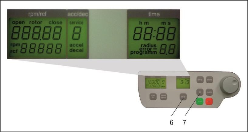
PRODUCT DESCRIPTION

 1.5 Operating and Display Elements

 11 12 1

 3

 8
 4
 10
 5

 6

 7

 9

 2

 1 central adjuster Run Parameters
 2 0-I Power Switch
 3 LCD Control Panel Display
 4 rpm/rcf Speed/ g-force
 5 accel/decel Acceleration / Deceleration Intensity
 6 time Centrifugation Time
 7 lid Lid Release
 8 quick Short Running
 9 start Start Centrifugation
 10 stop Stop Centrifugation
 11 prog Retrieving Programs
 12 store Program Store

2 Z326_V2.19_eng © Hermle Labortechnik GmbH
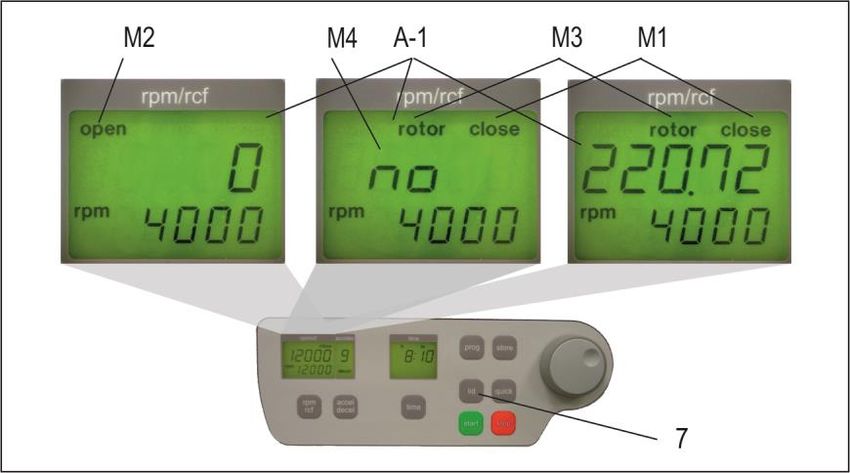
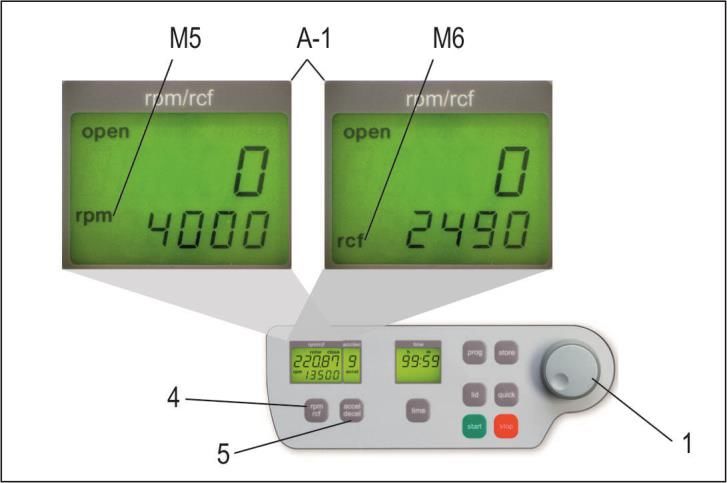
PRODUCT DESCRIPTION

 Indication:
 After switching on the centrifuge, the display, "rpm/rcf"(A-1) shows the loading status, the current
 software version and finally the model type (e.g. Z 36 HK).

 1.5.1 LCD-Display

 The following picture shows the individual elements of the LCD-display.

 Figure 1

 Display Fields:
 A-1 Display Field – "rpm/rcf"
 A-2 Display Field – "acc/dec"
 A-3 Display Field – "time"

 Messages/Logos of the Display Fields:
 M1 "close" M8 "decel"
 M2 "open" M9 "radius"
 M3 "rotor" M10 "program"
 M4 Rotor-No. M11 "error"
 M5 "rpm" M12 "service"
 M6 "rcf" M13 h m s
 M7 "accel"

© Hermle Labortechnik GmbH Z326_V2.19_eng 3
PRODUCT DESCRIPTION

 1.6 Signs and Indications of the Centrifuge

 1.6.1 General

 Direction of Rotation – clockwise rotation for the rotor drive

 Reference for Loading Rotors

 1.6.2 Product Nameplate (Example)

 Company Address: Hermle Labortechnik GmbH, Siemensstr. 25, D-78564 Wehingen

 TYPE: Type Designation of the Product

 REF: Order No. of the Product

 SN: Serial No. of the Product

 Manufacturer

 Date of Manufacture

 MAX. Drehzahl: Max. Speed Allowed of the Unit

 KIN. EN.: Max. Kinetic Energy with Corresponding Roto

 U/I/f: Allowable Voltage / Max. Current / Frequency

 P: Electrical Input Power

 Operating Manual Indication

 Labeling, Standards and Guidelines

 Instructions for Disposal

 RoHS Conformity

4 Z326_V2.19_eng © Hermle Labortechnik GmbH
PRODUCT DESCRIPTION

 1.6.3 Warning and Information Signs

 Four carrier must be used at all times on four places swing out
 rotors or damage will occur to the centrifuge. Such damage will
 not be covered under the product warranty

 Attention! Check the fastening of the rotor nut before each run

 Take off mains plug before opening the housing or the emergency
 release

 Power Input

 Rotation Direction Emergency Release

 Biohazard Warning

 1.6.4 Danger, Precautions and Warranty

 This device may only be operated by a trained professional. Carefully, read the operating
 manual and be familiar with the functions of the device.
 To protect people and the environment, the following precautions must be taken:
 • During centrifugation, the presence of people and the arrangement of hazardous materials is
 strictly prohibited, within 30 cm/12 in around the centrifuge, according to the regulations of
 EN 61010-2-020.
 • The HERMLE Z 326, is "non-explosion proof" and must not be operated in explosion-
 endangered areas or locations. Centrifugation of flammable, explosive, radioactive, or such
 substances, which chemically react with high energy, is strictly prohibited. If used in such
 environment, this is at the users own expense.
 • Never spin toxic or pathogenic material without adequate safety precautions, i.e.
 centrifugation of buckets / tubes with or without defective hermetic sealing, is strictly
 prohibited. The user is obliged to perform appropriate disinfection procedures, in case
 dangerous substances have contaminated the centrifuge and/or its' accessories. When
 centrifuging infectious substances, always pay attention to the General Laboratory
 Precautions. If necessary, contact your safety officer!
 • It is prohibited to run the centrifuge, with rotors not manufactured for this unit.
 • Under no circumstances open the lid of the centrifuge, while the rotor is still running or
 rotating with a speed of > 2m/s

 1.6.5 Following Rules Must Strictly be Adhered To:

 • Do not operate the centrifuge if not installed correctly.

© Hermle Labortechnik GmbH Z326_V2.19_eng 5
PRODUCT DESCRIPTION

 • Do not operate the centrifuge when dismounted (e.g. without housing).
 • Do not run the centrifuge, if mechanical or electrical assembly groups have been
 tampered with, by unauthorized personnel.
 • Do not use accessories such as rotors and buckets, that are not approved by HERMLE
 Labortechnik GmbH, except commercially available centrifuge tubes, made of glass or
 plastic.
 • Do not spin extremely corrosive substances, as they may cause material damages and impair
 mechanical resistance.
 • Do not operate the centrifuge with rotors or buckets, that show any signs of corrosion or
 mechanical damage.

 The manufacturer is responsible for safety and reliability, of the centrifuge, only if:
 • The unit is operated in accordance to this instruction manual.
 • Modifications, repairs or other adjustments are performed by HERMLE-authorized personnel
 and the electrical installation of the related location corresponds to the IEC-regulations.

 1.6.6 Warranty

 The centrifuge has been subjected to thorough testing and quality control. In the unlikely case of any
 manufacturing faults occurring, the centrifuge and rotors are covered by warranty, for a period of two
 years, from date of delivery. This warranty becomes invalid in any case of mishandling, damage
 and/or negligence and further in any case of usage of inappropriate spare parts and / or accessories
 or unauthorized modification of the unit.

 Technical modification rights are reserved, by the manufacturer, in regards to technical
 improvement!

6 Z326_V2.19_eng © Hermle Labortechnik GmbH
PRODUCT DESCRIPTION

 1.7 Installation of the Centrifuge

 1.7.1 Unpacking the Centrifuge

 Model Z 326 is supplied in a carton.
 Remove the strap retainer, open the carton, and remove the padding.
 Lift the centrifuge on both sides (see Figure 1) with an appropriate number of helpers and place it on
 the laboratory table.
 Attention! Do not lift the centrifuge from under the lid or by the front panel!

 Figure 1

 The instruction manual must be kept with the centrifuge, at all times.

 1.7.2 Space Requirements

 The centrifuge should be installed on an even, solid surface, if possible on a laboratory cabinet /
 table or some other solid vibration free surface.
 During centrifugation, the centrifuge must be placed in a way, that there is a minimum space of
 30 cm/11.81in on each side of the unit, according to EN 61010-2-020 standards.
 Do not place the centrifuge next to a window or a heater where it could be disposed to excessive
 heat, as the performance of the unit is based on an ambient temperature of 23°C/73.4°F.

 1.7.3 Installation

 Follow These Steps:
 • Check whether the power supply corresponds with the one specified on the manufacturer's rating
 label, mounted on the rear panel.
 • The power connection for the centrifuge requires a separate one-site protection, with 16 A (Type K)
 • In case of emergency, there must be an emergency switch off installed outside of the room, in order
 to disconnect the power supply from the unit.
 • Connect the centrifuge, with the mains.
 (The socket for the power cord must be easy to reach, respectively easy to disconnect).
 Switch on, by using the mains power switch (I).
 Open the lid, by using the button LID.
 • Remove the transport securing device of the motor.

© Hermle Labortechnik GmbH Z326_V2.19_eng 7
PRODUCT DESCRIPTION

 1.7.4 Attention before first use!

 Depending on how the motor shaft of your centrifuge is looking like, some action must be taken
 before the first operation. Please note the shape of the motor shaft of your centrifuge.
 There are two different versions:

 Cylindrical
 Conical
 motor shaft
 motor shaft

 Version 1 Version 2

 If the motor shaft is conical remove the collet from the rotor by turning it The collet is no longer
 counter clockwise needed

 If the motor shaft is cylindrical Let the collet inside the rotor

8 Z326_V2.19_eng © Hermle Labortechnik GmbH
PRODUCT DESCRIPTION

 1.8 Basic Adjustments

 At commissioning of the centrifuge, you have the options to make the following basic changes:
 - Acoustic Signal Turn On / Off
 - Keyboard Sound Turn On / Off
 - Volume Pre-Selection of Sound Signal
 - Song Selection - "end of run"

 1.8.1 Access to Mode: "Operating Data"

 If the centrifuge is still turned off, press the keys, "time" (6) and "lid" (7) simultaneously, turning on
 the main switch of the centrifuge. Now release both keys. As a result, a display test is administered
 for approx. 5 seconds. All possible indications will appear at the same time (see Figure 2).

 Figure 2

 Attention:
 - Please notice that you must enter the program as described, under point 1.8.1, to
 change the adjustments of the points 1.8.2 - 1.8.6. After the settings have been
 stored by user, the normal program mode can be changed back again by
 switching off the centrifuge, for a short period.

 - All changed settings must be confirmed by the key, "start" (9). A confirmation
 screen will appear with the word; "store" in the display box, "rpm/rcf"(A-1) - Only
 then, the pre-selections are valid, (see Figure 3).

© Hermle Labortechnik GmbH Z326_V2.19_eng 9
PRODUCT DESCRIPTION

 1
 7

 Figure 3

 1.8.2 Sound Signal Turn On / Off

 Proceed as illustrated, under point 1.8.1, to enter this program mode, press the key;2 "accel/decel"
 3 "L" with the
 (5). In the display, "accel/decel" (A-2) flashes the word, "service". Select the letter,
 adjustable knob (1). As a result, appearing in the display "rpm/rcf" (4), are the words, "On Sound".
 By pressing the key, "rpm/rcf" (4), the word "On" flashes, and the sound can be switched off with the
 adjustable knob (1), (see Figure 4).
 After the settings have been stored by user, the normal program mode can be changed back again
 by switching off the centrifuge, for a short period.

 Firgure 4

 1.8.3 Volume Pre-Selection of Sound Signal

 Proceed as illustrated, under point 1.8.1, to enter this program mode, press the key "accel/decel" (5).
 In the display, "accel/decel" (A-2), flashes the word, "service". Select the letter, "U" with the
 adjustable knob (1). As a result, appearing in the display, "rpm/rcf" (A-1), are the words, "Vol=0-
 9/Sound". By pressing the key, "rpm/rcf" (4), the desired volume can be adjusted between 0 (low)
 and 9 (loud), with the adjustable knob (1), (see Figure 5).
 After the settings have been stored by user (see 1.8.1), the normal program mode can be changed
 back again by switching off the centrifuge, for a short period.

10 Z326_V2.19_eng © Hermle Labortechnik GmbH
PRODUCT DESCRIPTION

 Figure 5
 8 9 1
 1.8.4 Song Selection - End of Run 7
 Proceed as illustrated, under point 1.8.1, to enter this program mode, press the key, "accel/decel"
 (5). In the display, "accel/decel" (A-2) flashes the word, "service". Select the letter, "G" with the
 adjustable knob (1). As a result, appearing in the display, "rpm/rcf" (A-1), the word " SonGo/Sound".
 After pressing the key „rpm/rcf“ (4), select a song with the adjusting knob (1), (see Figure 6).
 After the settings have been stored by user (see 1.8.1), the normal program mode can be changed
 back again by switching off the centrifuge, for a short period.

 Figure 6

 1.8.5 Keyboard Sound Turn On / Off

 Proceed as illustrated, under point 1.8.1, to enter this program mode, press the key, "accel/decel"
 (5). In the display; "accel/decel" (A-2) flashes the word, "service". Select the letter, "b" with the
 adjustable knob (1). As a result, appearing in the display, "rpm/rcf" (A-1), the word "ON/BEEP". By
 pressing the key, "rpm/rcf" (4), the keyboard sound (On) or (Off) can be turned on, with the
 adjustable knob (1), (see Figure 7).
 After the settings have been stored by user (see 1.8.1), the normal program mode can be changed
 back again by switching off the centrifuge, for a short period.

© Hermle Labortechnik GmbH Z326_V2.19_eng 11
PRODUCT DESCRIPTION

 Figure 7

 1.8.6 Retrieving Operating Data (operated by skilled or service engineer only!)

 In the function, "Basic Adjustments", retrieving the operating data of the centrifuge is an available
 option. Please proceed as illustrated, under point 1.8.1, to enter this program mode, press the key,
 "accel/decel" (5). In the display, "accel/decel" (A-2) flashes the word, "service".
 With the adjustable knob (1), the following information can be retrieved:
 A = Previous Starts of the Centrifuge
 H = Previous Operating Hours
 S = Software Version
 r = Converter Software
 E = List of Previous Error Message
 h = Running Time of the Motor
 The list of the last 99 error messages can be reviewed by pressing the key, "rpm/rcf" (4) and scroll
 through, with the adjustable knob (1). The respective error codes appear in the display, "rpm/rcf" (A-
 1). Please refer to Table 5: "Error Messages“, (see APPENDIX P.IX).

 Switch off the centrifuge, to return to the normal program mode.

 Figure 8

12 Z326_V2.19_eng © Hermle Labortechnik GmbH
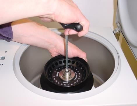
OPERATION

 2. OPERATION
 2.1 Mounting and Loading the Angle Rotor

 2.1.1 Installation of Rotors

 Clean the drive shaft and the collet with a clean, grease-free piece of cloth. Place the rotor onto the
 drive shaft, (see Figure 9). Please be sure that the rotor is fully installed onto the motor shaft.

 Figure 9 Figure 10

 Hold the rotor with one hand and secure the rotor to the shaft, by turning the fixing nut clockwise.
 Tighten the fixing nut with the provided Allen key, (see Figure 10)

 Figure 11

 ATTENTION: For safety, always ensure that the rotor fixing screw is tightened before
 each run, (see Figure 10)!!

 2.1.2 Loading Angle Rotors

 Rotors must be loaded symmetrically and with equal weight, (see Figures 12 and 13). The adapter
 may only be loaded with the appropriate vessels. The weight differences between the filled vessels
 should be kept as low as possible. Therefore, we recommend to weigh with a balance. This reduces
 the wear of drive and the acoustic operating noise.
 Each rotor indicates what the maximum capacity is per hole. (It is allowed to operate e.g. a 12-place-
 rotor with 2 or 4 loaded tubes only, but the loaded borings must be opposite of each other).

© Hermle Labortechnik GmbH Z326_V2.19_eng 13
OPERATION

 Figure 12: WRONG Figure 13: RIGHT (4 tubes)

 2.1.3 Loading Swing Out Rotors

 Loading of the buckets / vessels must be done in accordance, to Figure 15.
 It is allowed to operate e.g. a 4-place-rotor with 2 loaded buckets only. The loaded buckets must be
 opposite of each other. Make sure that the unloaded buckets are placed inside the rotor,
 (see Figures 14 and 15).
 In principle, swing out rotors cannot be removed during operation, until all buckets or racks
 are placed inside the rotor.
 The bolts of the rotor must be greased with the HERMLE Rotorgrease (Order No. 38-5656).
 The sample tubes have to be filled evenly, by eye, and set into the drillings or tube racks. The weight
 difference of the loaded buckets should not exceed 1.0 g.

 ATTENTION!
 Swing Out Rotors can be removed during operation, only if all locations are filled in with either
 4 buckets or 4 carriers – do not mix up buckets and carriers!!

 Figure 14: WRONG Figure 15: RIGHT

 ATTENTION!
 Do not operate the centrifuge with rotors or buckets that show any signs of corrosion
 or mechanical damage.
 Do not operate with extremely corrosive substances, which could damage the rotor
 and buckets.
 In case of any questions, please contact the manufacturer!

14 Z326_V2.19_eng © Hermle Labortechnik GmbH
OPERATION

 2.1.4 Loading and Overloading of Rotors

 All approved rotors are listed with their maximum speed and maximum filling weight, in
 Table 2: "Permissible Net Weight", (see APPENDIX P. VI).
 The maximum load permitted for a rotor is determined by the manufacturer, as well as the maximum
 speed allowed for this rotor (see label on rotor), must not be exceeded. The liquid the rotors are
 loaded with, should have a max. homogeneous density of 1.2 g/ml or less when the rotor is running
 at maximum speed.
 In order to spin liquids with a higher density, the speed has to be reduced, according to the following
 formula:
 1,2
 Reduced speed nred = √ x max. speed (nmax) of the rotor
 ℎ ℎ

 Example:
 1,2
 nred = √ x 4.000 = 3.360 rpm
 1,7

 In case of any questions, please contact the manufacturer!

 2.1.5 Removing the Rotor

 Completely, untighten the rotor fixing nut (2. screw over the stiff point) and lift the rotor vertically out of
 the centrifuge, (see Figures 9 and 10).

© Hermle Labortechnik GmbH Z326_V2.19_eng 15
OPERATION

 2.2 Lid

 2.2.1 Lid Release

 After the run, properly close the lid of the centrifuge, appearing in the display, "rpm/rcf"(A-1) with the
 word, "close" (M1). If there is a rotor in the centrifuge, the word, "rotor" (M3) appears, as well as the
 code number of the specified rotor, which is in the centrifuge, for example "220.72" (M4). If there is
 no rotor in the centrifuge, it flashes the word, "rotor" (M3) and an additional word, "no" (M4). ). By
 pressing the key, "lid" (7), the lid of centrifuge can be released. As soon as the electromagnetic lid is
 completely released, the word, "open" (M2) appears. The lid of the centrifuge is now able to be
 opened.

 For all number marked text, please refer to Figure 16.

 Figure 16

 During the run, you can retrieve the rotor type at any time, by pressing the key, “lid” (7).

 2.2.2 Lid Lock

 The centrifuge lid must be pressed with little force in the gasket. Keep the lid forced for a small
 period of time until it is closed by the motor driven lid lock. The word "open" (M2) will no longer be
 displayed.
 As a sign that the centrifuge is ready for starting, appearing in the display, "rpm/rcf"(A-1), the word
 "close" (M1). Simultaneously, the word "rotor" (M3) appears, as well as the code number of the
 rotor, which is in the centrifuge, i. e. "nr 22x.xx“ (M4), along with all rotor specific data, for example:
 max. speed, acceleration etc., are available.

 For all number marked text, please refer to Figure 17.

 ATTENTION: Don't grip your fingers between the lid and the device or the locking
 mechanism, when closing the lid!

16 Z326_V2.19_eng © Hermle Labortechnik GmbH
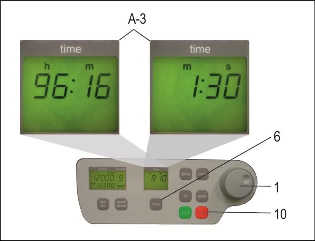
OPERATION

 2.3 Pre-Selection

 2.3.1 Pre-Selection of Speed / RCF-Value

 Selecting the key, "rpm/rcf" (4), pre-selection is activated. By pressing the key once, the word "rpm"
 (M5) flashes. By pressing the key again, the pre-selection of the centrifugal forces can be chosen.
 The flashing word, "rcf" (M6), will appear. The desired values can be selected, with the adjustable
 knob (1). In the display (A-1), the regulated value is shown permanently: before, during and after the
 run.

 For all number marked text, please refer to Figure 17.

 Figure 17

 As long as no rotor is inserted, the speed is adjustable between 200 rpm and the maximum
 revolution of the centrifuge.

 If there is a rotor in the centrifuge, the speed can only be pre-selected up to the maximum
 permissible revolution of that rotor. It is the same with the pre-selection of the RCF-Value. The
 setting range is between 20 xg and the maximum permissible centrifugal force of the rotor.
 See Table 3: "Max. Speed and RCF-Values for Permissible Rotor", (see APPENDIX P. VII). All
 important values are listed on this table.

 ATTENTION:
 Please check the maximum permissible revolutions of your test tubes! (Producer
 Indication)

 2.3.2 Pre-Selection of Running Time

 The running time can be pre-selected in 3 different ranges: from 10 seconds up to 99 hours 59
 minutes.
 1. Range from: 10 seconds up to 59 minutes 50 seconds, in steps of 10 seconds
 2. Range from: 1 hour up to 99 hours 59 minutes, in steps of 1 minutes
 3. Range: Continuous Run "cont", can be interrupted by the key, "stop" (10).
 -The running time can be pre-selected, with the lid opened or closed.
 -To activate the setting of the running time, press the key "time" (6).

© Hermle Labortechnik GmbH Z326_V2.19_eng 17
OPERATION

 -In the display, "time" (A-3) flashes the indication: "m : s" or "h : m", depending on the previous
 setting.
 To set the desired value, use the adjustable knob (1). After exceeding 59 min 50 sec, the indication
 changes automatically to, "h : m". After exceeding 99 hours 59 min, the word "cont" appears in the
 display, "time" (A-3). The continuous run can only be interrupted by pressing the key, "stop" (10).
 The time counts down, as soon as the set speed is reached.
 The display will always show the remaining running time, (see Figure 18)
 For all number marked text, please refer to Figure 18.

 Figure 18

 2.3.3 Pre-Selection of Brake Intensity and Acceleration

 Selecting the key, "accel/decel" (5), this function is activated.
 By pressing the key once, the word "accel" (M7) flashes, in the display "accel/decel" (A-2). The
 desired acceleration can be pre-selected, with the adjustable knob (1). The value 0 is equivalent to
 the lowest acceleration and the value 9 is equivalent to the highest acceleration.
 By pressing the key "accel/decel" (5) twice, in the display "accel/decel" (A-2), indicates the word
 "decel" (M8). Now the desired brake intensity can be pre-selected, with the adjustable knob (1). The
 value 9 is equivalent to the shortest possible brake time and the value 0 to longest possible brake
 time.
 For all number marked text, please refer to Figure 19.
 See Table 4: "Acceleration and Deceleration Times", (APPENDIX P. VIII). This table shows the
 acceleration and deceleration times, for the acceleration and deceleration stages 0 to 9, for
 permissible rotors.

 Figure 19

18 Z326_V2.19_eng © Hermle Labortechnik GmbH
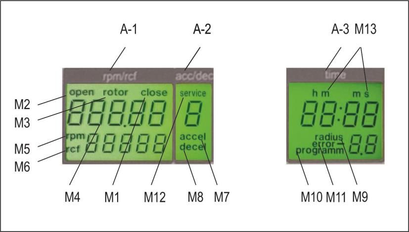
OPERATION

 2.4 Radius Correction

 If adapters or reducers are being used, it could change the centrifugal radius of the respective rotor.
 In that case, the radius can be corrected manually.
 Please proceed as follows:
 First close the centrifuge lid and press afterwards the key "time" (6) and the key "prog" (11) at the
 same time and hold down.
 In the display, "time" (A-3), appears the word "radius" (M9). With the adjustable knob (1), pre-select
 the respective radius correction, (see Table 6, APPENDIX P. X), in steps of 0.1cm m.
 As soon as the radius correction is set, the word "radius" (M9) appears. This text remains visible
 until the radius correction is set back to 0.

 For all number marked text, please refer to Figure 20.

 Figure 20

 2.5 Program

 2.5.1 Storage of Programs

 The program stores up to 99 runs, with all relevant parameters, including the used rotors. Any free
 program number is available and can be retrieved.
 Put the desired rotor into the centrifuge. By pressing the key, "prog" (11), in the display "time" (A-3)
 appears the word "program", (see Figure 21). With the adjustable knob (1), choose the desired
 program number.
 If a program number is already occupied, in the display "rpm/rcf" (A-1), the words "rotor" (M3) and
 "22x.xx" (M4) will appear, (see Figure 21). Free program numbers will appear as 0.

 Figure 21

© Hermle Labortechnik GmbH Z326_V2.19_eng 19
OPERATION

 Close the lid of the centrifuge, now proceed as described above, to set all important run parameters.
 If the lid isn´t closed, when storing the program in the display "rpm/rcf" (A-1), flashes alternately the
 word "FirSt" and "CLOSE Lid" (see Figure 25). When starting the run without storing the program, in
 the display "rpm/rcf" (A-1), flashes alternately the word ""First" and "PrESS StoreE", (see Figure 23).

 Figure 22 Figure 23

 For alteration of data, press the key "store" (12), for approx. 1 second. If the program is stored
 correctly, the word "StorE" appears in the display "rpm/rcf" (A-1). As a result, the word "program"
 (M10) disappears. As soon as the key "store" (12) is no longer displayed, the word "programm xx"
 (M10) reappears. ( the xx stands for the chosen program place).
 If all program numbers are occupied, take an old number that is not needed any longer and replace
 it with the new parameters.

 2.5.2 Recall of Stored Programs

 To recall stored programs, press the key "prog" (11), with the lid already closed. Inside the display
 "time" (A-3), appears "programm --"(M10). With the adjustable knob (1), pre-select the desired
 program number.
 In the respective displays, the stored values, for that program, will appear.
 If there is not the correct rotor inside the centrifuge, for the pre-selected program, in the display
 "rpm/rcf" (A-1) flashes the word "rotor" (M3). At the same time, the word "FALSE" and the stored
 rotor number "22x. xx“"(M4) flash in sequence of one another.
 For all number marked text, please refer to Figure 24.

 Figure 24

20 Z326_V2.19_eng © Hermle Labortechnik GmbH
OPERATION

 2.5.3 Leaving Program Mode

 To leave the program mode, press the key, "prog" (11). Then, inside the display "time", appears the
 word "programm".
 Set the display to "programm--" (M10) with the adjustable knob (1).
 For all number marked text, please refer to Figure 23.

 2.6 Starting and Stopping the Centrifuge

 2.6.1 Starting the Centrifuge
 Start the centrifuge with either the "start" key (9), or the "quick" key (8).
 With the "start" key (9), stored runs or runs with manually pre-selected parameters can be started.
 When the respective pre-selected running time has ended, the centrifuge will stop automatically.
 With the "quick" key (8), start runs, which will last a few seconds, can be initiated.
 By pressing the "quick" key (8), the centrifuge accelerates up to the pre-selected revolution.
 In the display "time" (A-3), the passed running time is indicated from the moment the "quick" key (8)
 is pressed.
 By releasing the "quick" key (8), the centrifuge stops and the running time is indicated, until the lid is
 opened.

 For all number marked text, please refer to Figure 25.

 Figure 25

 2.6.2 The "STOP" Key

 With the "stop" key (10), the run time can be interrupted, at any time, (see Figure 26). After pressing
 the key, the centrifuge decelerates with the respective pre-selected intensity, down to a standstill.

 Figure 26

© Hermle Labortechnik GmbH Z326_V2.19_eng 21
OPERATION

 2.7 Imbalance Detection

 In case the rotor is not equally loaded, the drive will turn off, during acceleration. The rotor decelerates
 to a standstill.
 When in the display "time" (A-3), the word "error" (M11) along with the number "01" appears, the
 weight difference of the samples are too large. Weigh out the samples exactly!
 Load the rotor as described in Chapters: 2.1.2 and 2.1.3.

 When inside the display "time" (A-3), the word "error" along with the number "02" appear, (see Figure
 27)
 Potential Reason for the Error Screen: The imbalance switch is defective.

 Figure 27

 2.8 Timerfunction

 This timer function enables to program a planned ending or start of centrifugation. After closing the
 centrifuge lid and setting all the needed values, the timer function can be activated.
 For this purpose press the bottom „time“ (6) for five seconds. This will take you to the time setting of
 the timer and the display "rpm/rcf" (A-1) shows the words "End in". The display „time“ (A-3) shows
 the remaining time until the end of the centrifugation. The remaining time can be set between 1 min
 and 99 h 59 min by pressing the bottom “time” (6) and turning the adjusting knob (1).
 Alternatively to the “End in” mode, you can choose the “Start in” mode by pressing the bottom
 „rpm/rcf“ (4). The display „time“ (A-3) shows the remaining time until the start of the centrifugation.
 The timer starts automatically after setting the needed value. The set time can be adjusted by
 pressing again the bottom “time” (6) and turning the adjusting knob (1).

22 Z326_V2.19_eng © Hermle Labortechnik GmbH
OPERATION

 You can interrupt this function by pressing the bottom “stop” (10) or the bottom “lid” (11). During the
 timer mode, all the other bottoms have no function.
 For all number marked text, please refer to Figure 28 and 29.

 Figure 28 Figure 29

© Hermle Labortechnik GmbH Z326_V2.19_eng 23
MAINTENANCE

 3. MAINTENANCE
 3.1 Maintenance and Cleaning

 3.1.1 General Care:

 Maintenance of the centrifuge is dependent on prolonging the life of the rotor, the rotor chamber and
 the rotor accessories. Please be sure to clean the accessories, especially the sealing of the aerosol-
 tight rotors and insert bolts, of swing out rotors. Following, lubricate the bolts or sealing, with the
 recommended HERMLE Rotorgrease - Order No.: 38-5656.
 Please pay special attention to anodized aluminum parts. Breakage of rotors can be caused by the
 slightest damages.

 In case of rotors, buckets or tube racks becoming in touch with corrosive substances, the affected
 area must be cleaned, thoroughly.

 Corrosive substances, such as, must be avoided: alkalis, alkaline soap solutions, alkaline amines,
 concentrated acids, solutions containing heavy metals, water-free chlorinated solvents, saline
 solutions, e.g. salt water, phenol, halogenated hydrocarbons.

 Cleaning – Units, Rotors, Accessories:
 - Turn the device off and disconnect from the power supply, before beginning any cleaning or
 disinfecting. Do not pour liquids into the housing interior.
 - Spray disinfectant on the device.
 - Thorough cleaning not only has its purpose in hygiene, but also in avoiding pollution based
 corrosion.
 - In order to avoid damaging anodized parts, such as rotors, reduction plates etc.; only pH-neutral
 Detergents, with a pH-value of 6-8, may be used for cleaning. Alkaline cleaning agents must
 not be used, (pH-value > 8).
 - After cleaning, please ensure all parts are dried thoroughly, either by hand or in a hot-air cabinet
 (Max. Temperature + 50°C/122°F).
 - It is necessary to coat anodized aluminium parts with anti-corrosion oil regularly, in order to
 increase their life-span and reduce corrosion predisposition.
 - Due to humidity or not hermetically sealed samples, condensation may form. The condensation
 has to be removed from the rotor chamber, with a soft cloth regularly.
 The maintenance procedure has to be repeated every 10 to 15 runs, but at least once a week!
 - Connect the unit to the power supply, after the equipment is completely dry.
 - Do not implement disinfection with UV-, beta- and gamma-rays or other high energy radiation.
 - Metal rotors can be autoclaved.
 - Rotor lid and adapters can also be autoclaved, (Max. 121°C/250°F, 20 min).
 - The tube racks are made of PP and cannot be autoclaved, at 134°C/273°F.

24 Z326_V2.19_eng © Hermle Labortechnik GmbH
MAINTENANCE

 For additional information on aerosol-tight rotors, lids and buckets, please see below
 The aerosol tightness of rotors, rotor lids, buckets and caps have been tested and certified by the
 "TÜV Nord CERT GmbH, Certification Body Consumer Products, Essen (Germany)", in accordance
 with Annex AA of IEC 61010-2-020. The certificates can be downloaded on our webpage,
 www.hermle-labortechnik.de. Aerosol-tight rotors and buckets are marked with the label, "aerosol-
 tight".
 ATTENTION: Autoclaving, mechanical stresses and contamination, by chemicals or other
 aggressive solvents, can impair the aerosol-tightness of the rotors and buckets.

 -Check the integrity of the seals of the aerosol-tight rotor lids or caps, before each use.
 -Use only aerosol-tight rotor lids or caps, if the seals are undamaged and clean.
 -Replace the seals of aerosol-tight lids and caps, after 5 autoclaving cycles.
 -Never store aerosol-tight rotors or buckets closed.

 3.1.2 Cleaning and Disinfecting of the Unit

 1. Open the lid, before turning off the unit. Disconnect from the power supply.
 2. Open the rotor nut, by turning the rotor key counter-clockwise.
 3. Remove the rotor.
 4. For cleaning and disinfection of the unit and the rotor chamber, use the above mentioned
 cleaner.
 5. Clean all accessible areas of the device and its accessories, including the power cord, with a
 damp cloth.
 6. Wash the rubber seals and rotor chamber thoroughly, with water.
 7. Rub the dry rubber seals with glycerol or talc, to prevent these from becoming brittle. Other
 components of the unit, e.g. the lid lock, motor shaft and rotor, should not be greased.
 8. Dry the motor shaft with a soft, dry and lint-free cloth.
 9. Examine the unit and accessories for damage.
 Remove adherent dust, at least every 6 months, from the ventilation slots in the centrifuge, by using
 a soft brush.
 *Before doing so, please switch off the unit and disconnect from the power supply.
 3.1.3 Cleaning and Disinfecting of the Rotor

 1. Clean and disinfect: the rotors, rotor lids and adapters, with the cleaner previously mentioned
 above.
 2. Use a bottle brush to clean and disinfect the rotor bores.
 3. Rinse the rotors, rotor lid and adapter, with clear water. Particularly, the drillings of the angle
 rotors.
 4. When drying the rotors and accessories, set on a towel. Place the angle rotors, with bores
 down, to dry.
 5. Dry the rotor cone with a soft, dry and lint-free cloth, check for damage. Do not grease the rotor
 cone.
 3.1.4 Disinfection of Aluminium Rotors

 In case of infectious material spilling into the centrifuge, the rotor and rotor chamber have to be
 disinfected, promptly after the run. Rotors may be autoclaved, at a maximum temperature of
 121°C/250°F.

© Hermle Labortechnik GmbH Z326_V2.19_eng 25
MAINTENANCE

 3.1.5 Disinfection of PP-Rotors

 Autoclaving
 The recommended time for autoclaving: 15 – 20 min at 121°C/250°F, (1 bar)
 ATTENTION: The sterilization time of 20 min. must not be exceeded. Continuous sterilization
 will cause reduction in the mechanical resistance, of the plastic material.
 Before autoclaving the PP-rotor and adapter, thoroughly clean to avoid the burning of dirty residue.
 Please disregard any consequences of chemical residues to plastic materials, at ambient
 temperatures. At high temperatures, autoclaving residue may corrode and destroy the plastic. The
 objects must be thoroughly washed with distilled water, after the cleaning, but before the
 autoclaving. Residues of any cleaning liquids, may cause fissures, whitening and stains.
 Gas Sterilization
 Adapters, bottles and rotors may be gas sterilized, with Ethylenoxyd. According to the duration of the
 application, allow items to properly air out, after the sterilization and before usage.

 ATTENTION: The temperature may rise during the sterilization; rotors, adapters and bottles
 should not be fully closed, keep completely unscrewed.

 Chemical Sterilization
 Bottles, adapters and rotors may be treated, with the usual liquid disinfectants.
 ATTENTION: Before applying any other, Cleaning Resp. Decontamination Method, other than
 what was recommended by the manufacturer, contact the manufacturer to ensure that it will
 not damage the unit or the rotor.

 3.1.6 Glass Breakage

 With high g-values, the rate of glass tube breakage increases. Glass splinters have to be removed
 immediately from rotor, buckets, adapters and the rotor chamber itself. Fine glass splinters will
 scratch and therefore damage the protective surface coating of a rotor. If glass splinters remain in
 the rotor chamber, fine metal dust will build up, due to air circulation. This very fine, black metal dust
 will severely pollute the rotor chamber, the rotor, the buckets, and the samples.
 If necessary, replace the adapters, tubes and accessories, to avoid further damage. Check the rotor
 bores regularly, for residue and damage.
 ATTENTION: Please check the relevant specifications of the tubes centrifuges with the
 manufacturer!

 3.2 Lifetime of Rotors, Round and Rectangular Buckets, Accessories

 Rotors and rotor lid made of aluminum or stainless steel, have a operating time of max. 7 years
 from first use.
 Transparent rotor lids and caps, made of PC or PP, as well as rotors, tube racks and adapters of
 PP, have a maximum operating time of up to 3 years, from first time use.
 Conditions for the Operating Time:
 Proper use, damage-free condition, recommended care.

26 Z326_V2.19_eng © Hermle Labortechnik GmbH
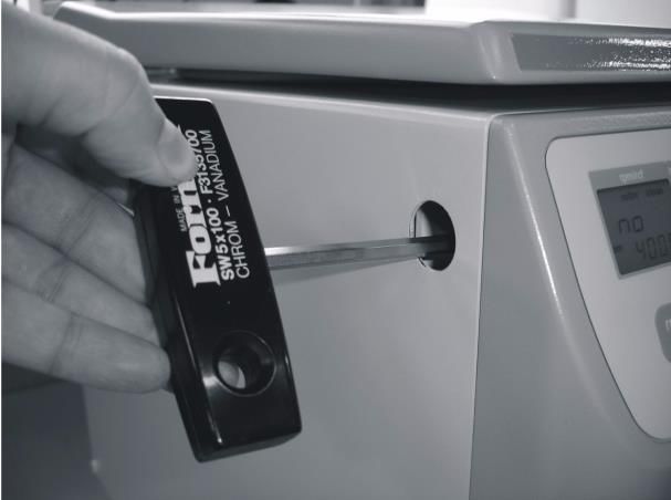
TROUBLE SHOOTING

 4. TROUBLE SHOOTING
 4.1 Error Message: Problem / Solution

 The error messages are listed to help localize possible errors faster.
 The possible error referred to in this chapter may not always be the case, as they are only theoretically
 occurring errors and solutions.
 Always keep us informed about any kind of error occurring, which is not listed in this chapter. With this
 information provided, we are able to improve and complete this operation manual.

 Many thanks in advance for your support.
 HERMLE Labortechnik GmbH

 4.2 Survey of Possible Error Messages and Solutions

 4.2.1 Lid Release during Power Failure (Emergency Lid Release)

 In case of power failure or malfunction, the lid of the centrifuge can be opened manually, in order to
 protect samples.

 Please proceed as follows (see Figure 30):
 • Switch off the centrifuge and unplug the power cord, wait until the rotor has come to a
 standstill (this may take several minutes)
 • On the left hand side of the centrifuge housing, there is a plastic stopper. Remove this
 stopper and behind is a hexagon nut.
 • Take the delivered box spanner, put it into the hole, and lock the box spanner, with the
 hexagon nut (see Figure 28).
 • Turn the box spanner to the right (clockwise), up to the limit.
 ATTENTION: Only turn to the limit, don´t tighten the nut.
 • Open the lid of the centrifuge.
 • Switch the centrifuge on again, to proceed with regular function.

 Figure 30

© Hermle Labortechnik GmbH Z326_V2.19_eng 27
TROUBLE SHOOTING

 4.2.2 Description of the Error Message System

 The error message, "error" (M11), is shown in the "time" (A-3) display, (see Figure 31). For more
 detailed information, refer to Table 5: "Error Messages", (see Appendix P.IX).

 Figure 31

 4.2.3 Procedure while error 14, from software version 1.76

 If Error 14 occurs, there is a problem with the speed sensor. The centrifuge lid is closed for
 undefined period of time and in the "rpm/rcf" (A-1) display shows the lettering "USEr GuidE" (see
 Figure 32).

 Figure 32

 To reopen the centrifuge lid, switch off the device and wait until the rotor has come to a standstill.
 Take from Table 4: Acceleration and Deceleration Times“ the maximum deceleration time of
 the respective rotor. Level 0 corresponds to unbreaked rundown, which occurs at error 14. If the
 centrifuge lid is opened before standstill of the rotor, a following error can occur.

28 Z326_V2.19_eng © Hermle Labortechnik GmbH
You can also read