Supplement to Austroads Guide to Road Design Part 4A: Unsignalised and Signalised Intersections - Road Planning and Design Manual Edition 2: ...
←
→
Page content transcription
If your browser does not render page correctly, please read the page content below
Road Planning and Design Manual
Edition 2: Volume 3

Supplement to Austroads Guide to Road Design
Part 4A: Unsignalised and Signalised Intersections
September 2020
Copyright
© The State of Queensland (Department of Transport and Main Roads) 2020.

Licence

This work is licensed by the State of Queensland (Department of Transport and Main Roads) under
a Creative Commons Attribution (CC BY) 4.0 International licence.

CC BY licence summary statement
In essence, you are free to copy, communicate and adapt this work, as long as you attribute the
work to the State of Queensland (Department of Transport and Main Roads). To view a copy of this
licence, visit: https://creativecommons.org/licenses/by/4.0/

Translating and interpreting assistance
                      The Queensland Government is committed to providing accessible services
                          to Queenslanders from all cultural and linguistic backgrounds. If you
                          have difficulty understanding this publication and need a translator,
                          please call the Translating and Interpreting Service (TIS National) on 13
                          14 50 and ask them to telephone the Queensland Department of
                          Transport and Main Roads on 13 74 68.

Disclaimer
While every care has been taken in preparing this publication, the State of Queensland accepts no
responsibility for decisions or actions taken as a result of any data, information, statement or
advice, expressed or implied, contained within. To the best of our knowledge, the content was
correct at the time of publishing.

Feedback
Please send your feedback regarding this document to: tmr.techdocs@tmr.qld.gov.au

Road Planning & Design Manual – Edition 2: Volume 3, Transport and Main Roads, September 2020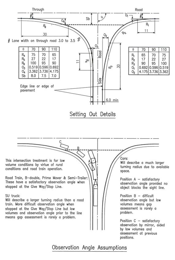
Relationship with Austroads Guide to Road Design – Part 4A (2017)

The Department of Transport and Main Roads has, in principle, agreed to adopt the standards
published in the Austroads Guide to Road Design (2017) Part 4A: Unsignalised and Signalised
Intersections.

When reference is made to other parts of the Austroads Guide to Road Design or the Austroads Guide
to Traffic Management, the reader should also refer to Transport and Main Roads related manuals:

    •   Road Planning and Design Manual (RPDM)

    •   Traffic and Road Use Management Manual (TRUM).

Where a section does not appear in the body of this supplement, the Austroads Guide to Road Design
– Part 4A criteria is accepted unamended.

This supplement:

    •   has precedence over the Austroads Guide to Road Design – Part 4A when applied in
        Queensland

    •   details additional requirements, including accepted with amendments (additions or
        differences), new or not accepted

    •   has the same structure (section numbering, headings and contents) as Austroads Guide to
        Road Design – Part 4A.

The following table summarises the relationship between the Austroads Guide to Road Design - Part
4A and this supplement using the following criteria:

                                Where a section does not appear in the body of this supplement, the
           Accepted
                                Austroads Guide to Road Design - Part 4A is accepted.

           Accepted with        Part or all of the section has been accepted with additions and or
           amendments           differences.

           New                  There is no equivalent section in the Austroads Guide.

           Not accepted         The section of the Austroads Guide is not accepted.

 Austroads Guide to Road Design – Part 4A                         RPDM relationship
  1 Introduction
  1.1   Purpose                                                    Accepted
  1.2   Scope of this Part                                         Accepted
  1.3   Design Criteria in Part 4A                                 Accepted with amendments
  1.4   Intersection Safety and the Safe System Approach           Accepted with amendments
  1.5   Grade Separation of Traffic Movements                      Accepted with amendments
  2 Layout Design Process
  2.1   Design Process                                             Accepted with amendments
  2.2   Alignment of Intersection Approaches                       Accepted with amendments
  2.3   Bicycles                                                   New

Road Planning & Design Manual – Edition 2: Volume 3, Transport and Main Roads, September 2020         i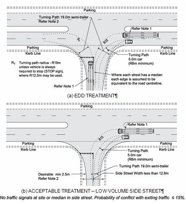
Austroads Guide to Road Design – Part 4A                           RPDM relationship
  3 Sight Distance
  3.1   General                                                     Accepted
  3.2   Sight Distance Requirements for Vehicles at Intersections   Accepted with amendments
  3.3   Pedestrian Sight Distance Requirements                      Accepted with amendments
  3.4   Sight Distance at Property Entrances                        Accepted with amendments
  4 Types of Intersection and their Selection
  4.1   General                                                     Accepted with amendments
  4.2   Intersection Types                                          Accepted
  4.3   Channelised Turn Treatments                                 New
  4.4   Warrants for BA, AU, and CH Turn Treatments                 New
  4.5   Median Turning Lanes or Two Way Right-Turn Lanes
                                                                    New
        (TWRTL) on an Urban Road
  5 Auxiliary Lanes
  5.1   General                                                     Accepted
  5.2   Deceleration Lanes                                          Accepted with amendments
  5.3   Acceleration Lane for Cars                                  Accepted with amendments
  5.4   Acceleration Lanes for Trucks                               Accepted
  5.5   Auxiliary Through-lane Design                               Accepted with amendments
  6 Traffic Islands and Medians
  6.1   Raised Traffic Islands and Medians                          Accepted with amendments
  6.2   Painted Traffic Islands and Medians                         Accepted
  6.3   Desirable Clearances to Traffic Islands and Medians         Accepted
  6.4   Road Width between Kerbs and between Kerb and Safety
                                                                    Accepted with amendments
        Barrier
  6.5   Kerb and Channel                                            Accepted with amendments
  7 Right-turn Treatments
  7.1   Design Procedure                                            Accepted
  7.2   Rural Right-left Staggered T-intersection                   Accepted
  7.3   Rural Right-turn Treatments – Divided Roads                 Accepted
  7.4   Rural Wide Median Treatment                                 Accepted with amendments
  7.5   Urban Right-turn Treatments – Undivided Roads               Accepted
  7.6   Urban Right-turn Treatments – Divided Roads                 Accepted with amendments
  8 Left-turn Treatments
  8.1   General                                                     Accepted with amendments
  8.2   Rural Left-turn Treatments                                  Accepted with amendments
  8.3   Urban Left-turn Treatments                                  Accepted with amendments
  9 Signalised Intersections
  9.1   Design Process                                              Accepted with amendments
  9.2   Sight Distance                                              Accepted with amendments
  References
  References                                                        Accepted with amendments

Road Planning & Design Manual – Edition 2: Volume 3, Transport and Main Roads, September 2020   ii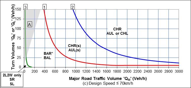
Austroads Guide to Road Design – Part 4A                        RPDM relationship
  Appendices
  Appendix A Extended Design Domain (EDD) for
                                                                 Accepted with amendments
             Intersections
  Appendix B Truck Stability at Intersections                    Accepted with amendments
  Appendix C Swept Paths for Road Trains at High Entry Angle
                                                                 Accepted
             Left-Turn Treatments
  Appendix D Basic Left-turn (BAL) Layouts at Rural              New
             Intersections
  Commentaries
  Commentary 1                                                   Accepted
  Commentary 2                                                   Accepted
  Commentary 3                                                   Accepted
  Commentary 4                                                   Accepted
  Commentary 5                                                   Accepted
  Commentary 6                                                   New

Road Planning & Design Manual – Edition 2: Volume 3, Transport and Main Roads, September 2020   iii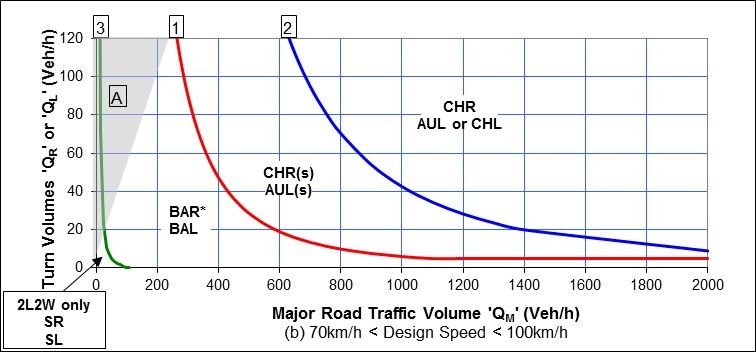
Contents

1     Introduction ....................................................................................................................................1
1.3   Design criteria in Part 4A ................................................................................................................ 1
1.4   Intersection safety and the safe system approach ......................................................................... 1
1.5   Grade separation of traffic movements .......................................................................................... 1
2     Layout design process ..................................................................................................................1
2.1   Design process ............................................................................................................................... 1
2.2   Alignment of intersection approaches ............................................................................................ 2
      2.2.1     Horizontal alignment .......................................................................................................2
      2.2.2     Vertical alignment ...........................................................................................................2
2.3   Bicycles ........................................................................................................................................... 3
3     Sight distance ................................................................................................................................4
3.2   Sight distance requirements for vehicles at intersections .............................................................. 4
      3.2.2      Safe Intersection Sight Distance (SISD) ........................................................................4
      3.2.3      Minimum Gap Sight Distance (MGSD)...........................................................................5
3.3   Pedestrian sight distance requirements ......................................................................................... 5
3.4   Sight distance at property entrances .............................................................................................. 5
4     Types of intersection and their selection ....................................................................................6
4.1   General ........................................................................................................................................... 6
4.3   Channelised turn treatments........................................................................................................... 6
4.4   Warrants for BA, AU and CH turn treatments ................................................................................. 6
4.5   Median turning lanes or Two-Way Right-Turn Lanes (TWRTL) on an urban road ........................ 6
5     Auxiliary lanes................................................................................................................................7
5.2   Deceleration lanes .......................................................................................................................... 7
      5.2.2      Determination of deceleration turning lane length..........................................................7
5.3   Acceleration lane for cars ............................................................................................................... 8
      5.3.1      General ...........................................................................................................................8
      5.3.2      Acceleration distance .....................................................................................................8
      5.3.4      Other considerations ................................................................................................... 11
5.5   Auxiliary through-lane design ....................................................................................................... 12
6     Traffic islands and medians ...................................................................................................... 12
6.1   Raised traffic islands and medians ............................................................................................... 12
      6.1.1      Raised islands ............................................................................................................. 12
      6.1.3      Raised high-entry angle and free-flow left-turn islands ............................................... 13
      6.1.4      Simple high entry angle design process ..................................................................... 13
6.4   Road width between kerbs and between kerb and safety barrier ................................................ 13
6.5   Kerb and channel .......................................................................................................................... 14
      6.5.1     General ........................................................................................................................ 15
7     Right-turn treatments ................................................................................................................. 15
7.4   Rural wide median treatment ........................................................................................................ 16

Road Planning & Design Manual – Edition 2: Volume 3, Transport and Main Roads, September 2020                                                          iv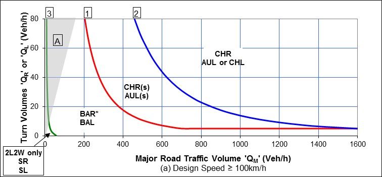
7.6 Urban right-turn treatments – Divided roads ................................................................................ 16
7.6.1 Channelised Right-turn (CHR) on divided urban roads ............................................... 16
7.6.3 Seagull treatments on divided urban roads ................................................................. 16
8 Left-turn treatments .................................................................................................................... 16
8.1 General ......................................................................................................................................... 16
8.1.3 Sight distance requirements ........................................................................................ 17
8.2 Rural left-turn treatments .............................................................................................................. 18
8.2.1 Rural Basic Left-turn treatment (BAL) ......................................................................... 18
8.2.5 Offset rural Channelised Left-turn lane treatment (CHL) ............................................ 19
8.3 Urban left-turn treatments ............................................................................................................. 20
8.3.1 Urban auxiliary left-turn treatment (AUL) on the major road ....................................... 20
8.3.2 Left-turn treatments for large vehicles ......................................................................... 20
9 Signalised intersections ............................................................................................................ 21
9.1 Design process ............................................................................................................................. 21
9.2 Sight distance ............................................................................................................................... 21
References ........................................................................................................................................... 22
Appendix A - Extended Design Domain (EDD) for intersections ................................................... 23
A.2 EDD for sight distance at intersections ......................................................................................... 23
A.2.2 Base and check cases ................................................................................................ 23
A.2.5 EDD Safe Intersection Sight Distance (SISD) ............................................................. 23
A.6 EDD treatment of a constrained left-turn radius ........................................................................... 23
A.10 EDD warrants for intersection turn treatments ............................................................................. 25
Appendix B - Truck stability at intersections ................................................................................... 31
B.2 Lateral friction force on vehicles ................................................................................................... 31
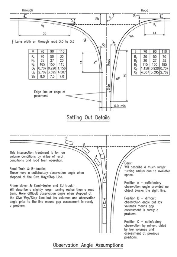
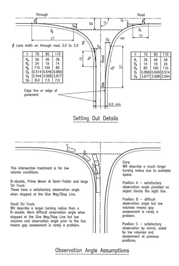
Appendix D - Basic Left-Turn (BAL) layouts at rural intersections ............................................... 32
Commentary 6 ...................................................................................................................................... 35
Tables
Table 4A-1 - Walking speeds for senior pedestrians .............................................................................. 5
Table 4A-2 - Length of acceleration lanes for cars on level grade .......................................................... 8
Table 4A-3 - Correction of acceleration distances as a result of grade ................................................ 10
Figures
Figure 4A-1 – Safe intersection sight distance ........................................................................................ 4
Figure 4A-2 – Two-way right turn lanes on an urban road ...................................................................... 7
Figure 4A-3 - Procedure for plotting a merge on a curved alignment using offsets from a straight road
............................................................................................................................................................... 12
Figure 4A-4 - Example of island treatments showing clearances at an intersection with single lane
carriageways and no specific bicycle facilities ...................................................................................... 14
Road Planning & Design Manual – Edition 2: Volume 3, Transport and Main Roads, September 2020 vFigure 4A-5 - Offset rural CHL treatment .............................................................................................. 20 Figure 4A-A 1 - Basic EDD Left Turn Treatment (BAL) on an urban road ............................................ 24 Figure 4A-A 2 - Basic Left Turn Treatment (BAL) on a rural road, side road < 50vpd AADT ............... 25 Figure 4A-A 3 - Warrants - major road turn treatments - Extended Design Domain ............................ 27 Figure 4A-A 4 - Calculation of the major road traffic volume parameter ‘QM’ ....................................... 29 Figure 4A-D 1 - Details of type 'BAL' layout for rural sites to suit B-double operation .......................... 32 Figure 4A-D 2 - Details of type 'BAL' layout for rural sites to suit type 1 (double) road train operation 33 Figure 4A-D 3 - Details of type 'BAL' layout for rural sites to suit type 2 (triple) road train operation ... 34 Road Planning & Design Manual – Edition 2: Volume 3, Transport and Main Roads, September 2020 vi
Supplement to Austroads Guide to Road Design Part 4A: Unsignalised and Signalised Intersections

1     Introduction
1.3    Design criteria in Part 4A

Differences

There is an editorial error in the 2nd sentence in the 2nd paragraph in Austroads Guide to Road
Design – Part 4A. The sentence should read 'Appendix A contains Extended Design Domain (EDD)
values …”

Additions

Guidance on the use of values outside of the design domain (Normal and Extended) should be
undertaken in accordance with this document and the Transport and Main Roads Guidelines for Road
Design on Brownfield Sites.

1.4    Intersection safety and the safe system approach

Additions

A Safe System approach to urban intersections is to design to optimise conditions for people walking
and cycling. The key conflict is where a turning motor vehicle driver fails to give way and could hit a
person continuing straight. Crash severity should be mitigated by designing for safer vehicle turning
speed and improving observation angles. To achieve this, high speed difference at conflict points
should be avoided such as at channelised left turns. Protected intersections with separated cycle
tracks provide a safe intersection for all road users. Refer to Transport and Main Roads Guideline
Selection and Design of Cycle Tracks for further information.

Transport and Main Roads Traffic Control (TC) Sign TC1775 is intended to warn other road users at
junctions where motorcyclists have a history of being hit by turning traffic.

Speed has been identified as a major contributing factor to the occurrence and severity of many
crashes at intersections. At rural intersections this factor is exacerbated due to the high-speed
differential between conflicting movements. Austroads Methods for Reducing Speeds on Rural Roads
– Compendium of Good Practice, AP-R449-14 describes methods for reducing speeds on rural roads
and includes a range of treatments for application at rural intersections.

1.5    Grade separation of traffic movements

Additions

A Safe System approach removes conflicts first, and then mitigates conflicts second. At urban
intersections a Safe System outcome would be to provide grade separation, where appropriate, for
vulnerable road users, for example, people walking and cycling, to eliminate conflicts with motorised
vehicles – see Transport and Main Roads Guideline Bicycle Rider and Pedestrian Underpasses.

2     Layout design process
2.1    Design process

Additions

In Table 2.1 of Austroads Guide to Road Design – Part 4A, the term 'cycle tracks', is to be added to
the second line in the Key considerations column corresponding to the third row relating to Traffic
lanes such that it reads – 'Road function may require bus lanes, transit lanes, tram lines, cycle tracks
or bicycle lanes'.

Road Planning & Design Manual – Edition 2: Volume 3, Transport and Main Roads, September 2020              1
Supplement to Austroads Guide to Road Design Part 4A: Unsignalised and Signalised Intersections

In Table 2.1, the line 'Urban roads with cycle tracks provide protected intersections - Refer Transport
and Main Roads Guideline Selection and Design of Cycle Tracks' is added to the 'Key considerations'
column corresponding to the sixth row relating to left and right turn treatments.

2.2       Alignment of intersection approaches

Additions

Treatments that reduce exposure, reduce the number of conflict points, encourage safe turning
speeds, and highlight conflict points and reduce impact speeds if the conflicts do occur, improve
intersection safety for all road users.

Where motorised vehicles cross the path of people walking or people cycling, high severity conflicts
can result, even if the relative speed is low. For example, for people walking or people cycling, the
fatality risk when hit by a vehicle travelling at 50 km/h is twice as high as the risk at 40 km/h and is
more than five times the risk compared to a vehicle travelling at 30 km/h at the conflict point. To
reduce the severity if a crash occurs involving a vulnerable road user, urban intersection design
should reduce the possible impact speed to as low as possible (
Supplement to Austroads Guide to Road Design Part 4A: Unsignalised and Signalised Intersections

      •    Where intersections are located on grades on the major road, the grade should preferably be
           less than 3% but can be accepted on grades of up to 6% with consideration given to the
           additional stopping / decelerating distance required in the downhill direction.

      •    Steeper grades can lead to problems with perception of the intersection in the uphill direction
           and stopping / deceleration issues in the downhill direction.

      •    If an intersection must be located within a large radius crest vertical curve, it can be located
           anywhere on the crest provided all sight distance parameters are met.

      •    Intersections located on short radii crest curves should be located at the apex of the crest (not
           either side) and, preferably, on straight horizontal alignment. These locations apply only to
           brownfields locations.

2.3       Bicycles

There is no equivalent Section 2.3 in Austroads Guide to Road Design – Part 4A.

New

Intersections are areas of high conflict and can be difficult for cyclists to traverse. The following
additional documents should be reviewed for additional specific design guidance for bicycles:

      •    Transport and Main Roads Technical Guidelines for Cyclists and Pedestrians (via the
           departmental website https://www.tmr.qld.gov.au/business-industry/Technical-standards-
           publications/Cycling-guidelines), and

      •    Transport and Main Roads Traffic and Road Use Management Manual (TRUM).

Transport and Main Roads requires the design for bicycles to be an integral part of the design of the
various components of the road, not an ‘add-on’ after the basis for the design has been established.

In accordance with the Transport and Main Roads Cycling Infrastructure Policy, road upgrades are to
incorporate ‘cycle-friendly’ designs. Along priority cycling routes, these cycle friendly designs are
marked cycle lanes, cycle paths, shared paths or other facilities for cyclists.

A ‘cycle-friendly’ design feature of urban intersections is the provision of 1.0 m minimum offsets from
the edge of lane to kerb faces where there is no other provision for cyclists (e.g. there is no separate
bicycle lane). This is to avoid cyclists having to negotiate ‘squeeze points’ at the intersection. On the
major road in rural areas, the minimum offset is the greater of the shoulder width and 1.0 m.

If bicycle lanes are present either side of an intersection, specific cycle facilities are to be provided to
guide cyclists through the intersection. Even a short-marked cycle lane through an intersection that
does not provide route continuity may provide safety advantages to cyclists provided that its
termination point does not lead cyclists into an unsafe situation.

Where there are a high number of cyclists or an intersection has a poor cycle safety record, a green
coloured pavement surface for the cycle lane may deliver added cycle safety. Refer to the Transport
and Main Roads TRUM Manual for guidance on the use of green coloured pavement surfaces.

Wide kerbside lanes enable greater separation of cyclists and motor vehicles, creating a higher level
of safety and increased operational efficiency. Wide kerbside lanes should be carried through
intersections to avoid ‘squeeze points’.

Where a road is identified as a principal cycling route, a bike lane treatment on the uphill leg(s) may be
appropriate to account for side-to-side movement of the bicycle and the large speed differential
between bicycles and motorised vehicles uphill. A bicycle lane is also desirable on the downhill leg(s).

Road Planning & Design Manual – Edition 2: Volume 3, Transport and Main Roads, September 2020                  3
Supplement to Austroads Guide to Road Design Part 4A: Unsignalised and Signalised Intersections
3 Sight distance
3.2 Sight distance requirements for vehicles at intersections
Additions
Safe Intersection Sight Distance (SISD) and Minimum Gap Sight Distance (MGSD) represent separate
and independent sight distance models. It cannot be assumed that meeting the requirements of one
will be sufficient to meet the requirements of the other. It is mandatory that each of these sight
distance models are checked and adequately provided for as part of the design process for all
intersections and property accesses.
3.2.2 Safe Intersection Sight Distance (SISD)
Difference
Figure 3.2 of Austroads Guide to Road Design – Part 4A incorrectly depicts the location of the driver
position based on distance from the lip of channel or edge line. In the current version of Austroads
Guide to Road Design – Part 4A (2017), this location is measured from the conflict point. The top
portion of Figure 3.2 is therefore replaced with the Figure 4A-1.
Figure 4A-1 – Safe intersection sight distance
Additions
The time gaps provided by applying the SISD model are generally sufficient for heavy vehicles to
undertake the following movements:
• left or right-turn from the minor road onto the major road
• through movement from the minor road at a cross intersection, and
• right-turn from the major road into the minor road.
However, the time gaps may not be sufficient for heavy vehicles to undertake these movements in
particular circumstances, for example:
• where the design heavy vehicle is greater than a 19 m semi-trailer
• the major road is on a steep grade, and
• the major road comprises more than one lane in each direction.
Under such circumstances, advice from Transport and Main Roads' specialists should be sought as to
whether the minimum values of SISD are sufficient to cover the particular heavy vehicle movements.
Road Planning & Design Manual – Edition 2: Volume 3, Transport and Main Roads, September 2020 4Supplement to Austroads Guide to Road Design Part 4A: Unsignalised and Signalised Intersections
3.2.3 Minimum Gap Sight Distance (MGSD)
Additions
An additional note is added to Table 3.5 of Austroads Guide to Road Design – Part 4A as follows:
Note: the critical acceptance gaps (ta) listed are based on simple road layouts with an assumed 3.5 m
wide lane and no median width to cross. Any geometric features that increase the crossing distance
therefore require an increase in the values of ta to be applied. These factors include, a skewed
crossing path, auxiliary turn lanes and bicycle lanes, wide centreline treatments and narrow medians.
3.3 Pedestrian sight distance requirements
Additions
Pedestrian walking speeds can vary significantly and are affected by age, sex, motivation, presence of
other pedestrians and other traffic impediments. The distribution of free flow walking speeds varies as
follows:
• minimum walking speed 0.74 m/s
• maximum walking speed 2.39 m/s
• maximum speed of wheelchairs 10 km/h = 2.78 m/s (wheelchairs are classified as pedestrians
in legislation), and
• average unimpeded free-flow 1.35 m/s walking speed.
Calculation of green time at traffic signals is based on an average design walking speed of 1.2 m/s,
but this is still faster than some pedestrians can manage. In particular, elderly pedestrians often adopt
significantly lower speeds than the younger part of the population. Table 4A-1 provides guidance on
the walking speed to adopt for various circumstances.
Table 4A-1 - Walking speeds for senior pedestrians
Walking Pace Mean Speed (m/s) 10th Percentile Speed (m/s)
Normal 1.13 0.8
Hurried 1.41 1.0
Rushing 1.71 1.0
3.4 Sight distance at property entrances
Additions
In existing, constrained situations, where it is deemed impractical to achieve the sight distance criteria
as described in Austroads Guide to Road Design – Part 4A, it should be sought, as a minimum, to
comply with the sight distance criteria as per Section 3.2.4 – Sight distance at access driveway exits,
in Australian Standard AS 2890.1:2004 Parking facilities – Off-street car parking.
At many properties (for example major shopping centres), the entrance may appear to a driver to be
an intersection as opposed to the more common form of a property entrance. Due to the variety of
different designs and pavement/kerb treatments that can be used at property entrances, no clear
distinction can be made as to what is an intersection and what is a property entrance.
In considering the sight distance requirements to be applied at a property entrance, a judgement is to
be made on the basis that if drivers are likely to consider that a property entrance looks like an
intersection, then it should be designed in accordance with the requirements for an intersection.
Road Planning & Design Manual – Edition 2: Volume 3, Transport and Main Roads, September 2020 5Supplement to Austroads Guide to Road Design Part 4A: Unsignalised and Signalised Intersections 4 Types of intersection and their selection 4.1 General Additions Where urban roundabouts or signalised intersections are located on a bicycle route, protected intersections and cycle tracks should be considered. Refer Transport and Main Roads Guideline Selection and Design of Cycle Tracks, Section 4. 4.3 Channelised turn treatments There is no equivalent Section 4.3 in Austroads Guide to Road Design – Part 4A. New Refer to Austroads Guide to Road Design – Part 4, Appendix A, Section A.7 and the corresponding section in the RPDM, Supplement to Austroads Guide to Road Design - Part 4. 4.4 Warrants for BA, AU and CH turn treatments There is no equivalent Section 4.4 in Austroads Guide to Road Design – Part 4A. Refer to Austroads Guide to Road Design – Part 4, Appendix A, Section A.8 and the corresponding section in the RPDM, Supplement to Austroads Guide to Road Design - Part 4. New An EDD version of these warrants for potential application at constrained and brownfields sites is provided at Appendix A.10 of this RPDM, Supplement to Austroads Guide to Road Design, Part 4A. Further commentary on the methodology behind these warrants is provided at Commentary 6 of this document. 4.5 Median turning lanes or Two-Way Right-Turn Lanes (TWRTL) on an urban road There is no equivalent Section 4.3 in Austroads Guide to Road Design – Part 4A. New Median Turning Lanes or Two-Way Right Turn Lanes (TWRTL) can be used to maintain capacity and level of service for the through lanes by removing the obstruction caused by a right-turning vehicle. It has the added advantage of providing shelter for vehicles both entering and exiting from an access. A diagram of such a treatment is shown in Figure 4A-2. This treatment is particularly applicable in commercial and residential areas with closely spaced access points. It has been used successfully where arterial roads bisect country town business and industrial areas and access is required for motels, service centres commercial establishments and adjoining low traffic volume side streets. TWRTLs should not be introduced without consideration of existing and future land use. They should not be allowed to provide unlimited and uncontrolled right-turn movements. However, when used on roads with traffic signal control, TWRTLs may provide sufficient gaps to adequately service low volume side properties with efficiency and safety. In non-access controlled areas, they can encourage ad-hoc land development with inappropriate accesses provided at developments. On new heavily travelled arterial roads and commercial and industrial areas with widely spaced access points, median control of right-turn movements is preferred. Road Planning & Design Manual – Edition 2: Volume 3, Transport and Main Roads, September 2020 6
Supplement to Austroads Guide to Road Design Part 4A: Unsignalised and Signalised Intersections

TWRTLs should be restricted to the urban environment with travel speeds of 70 km/h or less. They
should not be used in high density residential areas due to the potential conflict with uncontrolled
pedestrian movements.

A TWRTL must not be used in conjunction with an intersection. The ends of the TWRTL treatment
must not be closer than 10 m from the start of any right-turn lane at an intersection.

The through road should have no more than two lanes in each direction resulting in a total of five lanes
with the introduction of a TWRTL.

Geometric considerations

The TWRTL is to be paved flush with the adjacent lanes. To improve the definition of the lane a
different coloured pavement material other than red (Bus Only lanes) or green (Cycle lanes) can be
used. The desirable width is 3.0 m to 4.8 m. TWRTLs and right-turn auxiliary lanes within the same
length of median must be separated by a raised island and adequately sign posted.

Figure 4A-2 – Two-way right turn lanes on an urban road

Notes:
1. This diagram does not show any specific bicycle facilities. Where specific bicycle facilities are required (e.g.
   exclusive bicycle lanes), refer Austroads – Cycling Aspects of Austroads Guides AP-G88-17.
2. See Transport and Main Roads Manual of Uniform Traffic Control Devices (MUTCD) for linemarking, spacing
   of pavement arrows, advance warning and regulatory signs.
3. Minimum offset is as per Figure 6.3 of Austroads Guide to Road Design – Part 4A.
4. Diagram shows two lanes in each direction, but this treatment can be used for roads with a single lane in each
   direction.

5     Auxiliary lanes
5.2      Deceleration lanes

5.2.2     Determination of deceleration turning lane length

Additions

Low to moderate speed urban arterial road intersections

Where the entry to the auxiliary left lane crosses a bicycle lane on the approach to an urban
intersection, a high-speed conflict area can result in high severity rear-end and side-swipe crashes. In

Road Planning & Design Manual – Edition 2: Volume 3, Transport and Main Roads, September 2020                         7
Supplement to Austroads Guide to Road Design Part 4A: Unsignalised and Signalised Intersections

urban areas, this conflict can be avoided by designing a transition from bicycle lane to cycle track and
a protected intersection. Refer Transport and Main Roads Guideline Selection and Design of Cycle
Tracks, Section 4.

5.3      Acceleration lane for cars

5.3.1     General

Additions

Note to Figure 5.4 of Austroads Guide to Road Design – Part 4A. The emergency run-off area is to be
designed as per the requirements detailed in RPDM, Volume 3, Part 3, Geometric Design,
Section 9.4.

At intersections on urban roads where people are likely to be walking or cycling, free flow acceleration
lanes can result in conflicts, therefore it is recommended in such situations to consider alternative turn
treatments. Transport and Main Roads Guideline Selection and Design of Cycle Tracks presents
intersection forms which mitigate the risk associated with conflicts for cyclists.

5.3.2     Acceleration distance

Differences

All references to Tables 5.4 and 5.5 in this section of Austroads Guide to Road Design – Part 4A are
to be replaced respectively with references to Tables 4A-2 and 4A-3.

Replace 'Table 5.4: Length of acceleration lanes for cars on a level grade (and associated notes) with
Table 4A-2 (and associated notes).

Table 4A-2 - Length of acceleration lanes for cars on level grade

   Design                   Length of acceleration lane A (m)                   4 sec     Merge         Min
  speed of          (including length of merge taper) – for flat grade          travel    TM (M)     desirable
    road                                                                          (m)                 length 4
                           Design speed of entry curve (km/h)
  entered(1)                                                                                         sec + TM(3)
   (km/h)           0(2)
                           20     30      40      50      60     70      80
         50         70     60     50      30       -       -        -     -       55        50           105
         60         100    95     85      65      35       -        -     -       65        60           125
         70         140    135    125     105     75      45        -     -       80        70           150
         80         215    205    195     175    150     115        75    -       90        80           170
         90         300    295    280     265    235     200     160      90      100       90           190
         100        405    395    385     365    340     305     265     195      110       100          210
         110        600    590    580     560    535     500     460     385      120       105          225

Notes:
1. For the purpose of calculating the acceleration lane lengths at intersections, the speed reached is usually
   made equal to the mean free speed of the through road as defined in the RPDM Volume 3, Part 3 Geometric
   Design. In the absence of local data, it can be assumed that the mean free speed is approximately equal to
   the speed limit.
2. Length required where a vehicle accelerates from a zero speed.
3. Minimum desirable values have been rounded.

Road Planning & Design Manual – Edition 2: Volume 3, Transport and Main Roads, September 2020                    8
Supplement to Austroads Guide to Road Design Part 4A: Unsignalised and Signalised Intersections
General Notes:
• Values in the non-shaded areas are based on the distance required to accelerate from the turning speed to
the mean free speed of the road being entered.
• For values in the green-shaded areas adopt the minimum desirable length as in this area of the table these
values are greater than the distance to accelerate from the turning speed to the design speed of the road
being entered.
• Values shown in table are for level grade. Adjust for grade using Table 4A-3. Flat grade is any road with a
grade given by 1% downgrade ≤ grade ≤ 1% upgrade.
The values in Tables 4A-2 and 4A-3 have been generated from VEHSIM acceleration curves for a
typical car. The VEHSIM curves are reproduced in RPDM, Volume 3, Part 4C Interchanges,
Commentary 9.
In practice the vertical profile of an acceleration lane may consist of sections of varying grade due to
design issues such as the natural topography or other constraints. In these situations, the overall
length of the acceleration lane required can be established by determining the vehicle speed at the
start of the final section of grade, and determining the remaining length required for vehicles to meet
the required design speed. A worked example of determining lane lengths on compound grades is
included at RPDM, Volume 3, Part 4C Interchanges, Commentary 9.
Replace Table 5.6: Correction of acceleration distances as a result of grade and associated notes with
Table 4A-3 (and associated notes).
Road Planning & Design Manual – Edition 2: Volume 3, Transport and Main Roads, September 2020 9Supplement to Austroads Guide to Road Design Part 4A: Unsignalised and Signalised Intersections
Table 4A-3 - Correction of acceleration distances as a result of grade
Design Ratio of acceleration length on grade to acceleration length on level (Table 4A-2)
speed (1)
Design speed of turning roadway curve (km/h)
of road 1% < upgrade ≤ 3% 1% < downgrade ≤ 3%
entered
0 20 30 40 50 60 70 80 0 20 30 40 50 60 70 80
(km/h)
50 1.05 1.10 1.10 1.15
0.95 0.90 0.90 1.00
60 1.10 1.10 1.05 1.10 1.15
0.95 0.95 0.90 0.90 1.00
70 1.15 1.10 1.10 1.15 1.20 1.10
0.95 0.95 0.90 0.90 0.95 0.90
80 1.15 1.15 1.15 1.15 1.15 1.15 1.15
0.90 0.90 0.85 0.90 0.85 0.85 0.80
90 1.20 1.15 1.20 1.20 1.20 1.25 1.20 1.30
0.90 0.85 0.90 0.85 0.85 0.85 0.80 0.85
100 1.20 1.20 1.20 1.20 1.20 1.25 1.25 1.25
0.85 0.85 0.85 0.85 0.85 0.85 0.85 0.80
110 1.40 1.40 1.40 1.45 1.45 1.45 1.50 1.55
0.80 0.80 0.80 0.80 0.80 0.75 0.75 0.75
3% < upgrade ≤ 5% 3% < downgrade ≤ 5%
50 1.15 1.15 1.20 1.35 0.85 0.90 0.80 0.85
60 1.25 1.20 1.25 1.25 1.30 0.90 0.85 0.80 0.75 0.85
70 1.25 1.25 1.30 1.30 1.30 1.30 0.90 0.85 0.85 0.80 0.80 0.80
80 1.35 1.40 1.40 1.45 1.45 1.50 1.60 0.80 0.80 0.75 0.75 0.75 0.75 0.65
90 1.45 1.45 1.50 1.50 1.55 1.60 1.70 1.70 0.80 0.75 0.75 0.75 0.75 0.75 0.70 0.70
100 1.55 1.55 1.55 1.60 1.60 1.65 1.70 1.70 0.75 0.75 0.75 0.75 0.75 0.70 0.70 0.70
110 (2)
0.70 0.70 0.65 0.65 0.65 0.65 0.65 0.60
5% < upgrade ≤ 6% 5% < downgrade ≤ 6%
50 1.30 1.35 1.40 1.50 0.85 0.85 0.80 0.85
60 1.40 1.35 1.40 1.45 1.55 0.85 0.85 0.80 0.75 0.85
70 1.45 1.45 1.45 1.50 1.55 1.55 0.80 0.80 0.80 0.80 0.80 0.80
80 1.75 1.80 1.80 1.90 1.95 2.10 2.40 0.75 0.75 0.70 0.70 0.70 0.65 0.60
90 2.00 2.00 2.10 2.10 2.20 2.35 2.55 2.55 0.70 0.70 0.70 0.70 0.65 0.65 0.60 0.60
100 2.15 2.20 2.20 2.25 2.30 2.40 2.55 2.55 0.70 0.70 0.70 0.65 0.65 0.65 0.60 0.60
110 (2)
0.60 0.60 0.60 0.60 0.55 0.55 0.55 0.55
Notes:
1. For the purpose of calculating the acceleration lane lengths at intersections, the speed reached is usually
made equal to the mean free speed of the through road as defined in the RPDM Volume 3, Part 3 Geometric
Design. In the absence of local data, it can be assumed that the mean free speed is approximately equal to
the speed limit.
2. Empty cells at these speeds indicate that the modelled acceleration does not result in vehicles reaching
110 km/h. In these cases, the acceleration lanes should be converted to an added lane.
General Notes:
• Values in the non-shaded areas are based on the distance required to accelerate from the turning speed to
the design speed of the road being entered.
• For values in the green-shaded areas adopt the minimum desirable length from Table 4A-2, as in this area of
the table these values are greater than the grade corrected distance to accelerate from the turning speed to
the design speed of the road being entered.
Road Planning & Design Manual – Edition 2: Volume 3, Transport and Main Roads, September 2020 10Supplement to Austroads Guide to Road Design Part 4A: Unsignalised and Signalised Intersections
5.3.4 Other considerations
There is no equivalent Section 5.3.4 in Austroads Guide to Road Design – Part 4A. This section was
previously included within Austroads Guide to Road Design – Part 4A and has been removed from the
2017 version. The department considers that this information remains worthwhile and hence the
original information is now presented in this part of the RPDM.
New
For safety reasons merges should never be installed:
• Over a crest that has a sight distance less than Approach Sight Distance (ASD) or on the
inside of a horizontal curve where the radius of the right-side lane line is less than:
− 185 m for a 60 km/h design speed
− 330 m for a 80 km/h design speed
− 515 m for a 100 km/h design speed, and
− 620 m for a110 km/h design speed.
This is based on a 3.5 m lane width and a 2 s gap. For 3.0 m wide lanes a 20% larger radius applies.
It is also important that:
• ASD is available at all points along the merge length to allow drivers to observe the
linemarking with sufficient time to react.
• Merge transitions around horizontal curves should be developed as for a straight alignment
and transferred to the curved alignment by the distance and offset method. This is shown in
Figure 4A-3.
• A circular curve should not be used for the merge taper, as the rate of lateral movement and
reduction in width will not be uniform. In plane geometry, concentric circular arcs cannot be
joined tangentially by a third circular arc, unless they are joined over exactly 180°. The curve
within the merge length in the bottom half of Figure 4A-3 is obtained by linear interpolation
only; it is not a circular arc.
Where an intersection is located downstream of the end of the acceleration lane it is important to verify
that sufficient weaving distance is available for drivers using the acceleration lane who wish to turn
right at that intersection. The same applies to drivers in the through lane who may wish to turn left at
that intersection (Figure 5.4 (b) of Austroads Guide to Road Design – Part 4A). This will require traffic
analysis in accordance with the Guide to Traffic Management.
Road Planning & Design Manual – Edition 2: Volume 3, Transport and Main Roads, September 2020 11Supplement to Austroads Guide to Road Design Part 4A: Unsignalised and Signalised Intersections Figure 4A-3 - Procedure for plotting a merge on a curved alignment using offsets from a straight road Source: Austroads (2005). 5.5 Auxiliary through-lane design Additions The start and termination points of an auxiliary lane should be clearly visible to approaching drivers in accordance with the sight distance requirements outline in Table 9.7 in Austroads Guide to Road Design – Part 3 and the additional considerations for merge points discussed at Section 5.3.4. The department requires that a run-out area be provided for the merge area of all auxiliary lanes. 6 Traffic islands and medians Additions General design guidance on traffic islands and medians at intersections is provided in Appendix A.15 of Austroads Guide to Road Design – Part 4. 6.1 Raised traffic islands and medians 6.1.1 Raised islands Additions Semi-mountable kerbs are preferred for raised islands and medians. However, in some locations, a barrier kerb type may be appropriate. Guidance on the selection and application of the various kerb types is discussed in Table A 3 of Austroads Guide to Road Design – Part 4A. Further information on kerb types and their application in Queensland is detailed in RPDM Volume 3, Part 3 Geometric Design. Road Planning & Design Manual – Edition 2: Volume 3, Transport and Main Roads, September 2020 12
Supplement to Austroads Guide to Road Design Part 4A: Unsignalised and Signalised Intersections

Islands at intersections should be designed to suit turning paths of design vehicles and may need to
consider the use of mountable islands in some circumstances. The design of the islands should
ensure that the continuity of the major road through the intersection is maintained and is legible for
approaching drivers.

6.1.3    Raised high-entry angle and free-flow left-turn islands

Additions

At intersections on urban roads where people are likely to be walking or cycling, high-entry angle
treatments and free-flow acceleration lanes can result in conflict, therefore in such situations
consideration should be given to alternative turn treatments. Transport and Main Roads Guideline
Selection and Design of Cycle Tracks presents intersection forms which mitigate the risk associated
with conflicts for cyclists. If a left turn slip lane is deemed necessary, it should either be signalised or
have a wombat crossing (raised zebra) provided.

Channelised left turns are not appropriate where cycle tracks continue through at an urban protected
intersection – refer to Transport and Main Roads Guideline Selection and Design of Cycle Tracks.

6.1.4    Simple high entry angle design process

Additions

Alternative A2 – CHL turn treatment with acceleration lane

Suitable for use at rural sites but alternatives should be considered at urban sites, to minimise conflicts
with people walking and people cycling – refer to Section 6.1.3 above.

Alternative B2 – CHL turn treatment with acceleration lane – Urban

The department’s preference is that alternative treatments are considered to free flow acceleration
lanes at urban sites, to minimise conflicts with people walking and people cycling – refer to
Section 6.1.3 above.

6.4     Road width between kerbs and between kerb and safety barrier

Additions

Figure 4A-4 was previously included within Austroads Guide to Road Design – Part 4A and has been
removed from the 2017 version. The department considers that this information remains worthwhile
and hence the original information is now presented in this part of the RPDM.

Road Planning & Design Manual – Edition 2: Volume 3, Transport and Main Roads, September 2020                  13
Supplement to Austroads Guide to Road Design Part 4A: Unsignalised and Signalised Intersections

Figure 4A-4 - Example of island treatments showing clearances at an intersection with single
lane carriageways and no specific bicycle facilities

Notes:
1. Minimum desirable width between kerbs to allow for a broken-down vehicle is 5.0 m. This width is not
   mandatory if other provisions for passing broken-down vehicles are provided. Such provisions may include
   mountable or semi-mountable kerbing on islands / medians with sufficient offset to hardware (e.g. signs, light
   poles and traffic signal posts) to allow a very slow passing manoeuvre.
2. Offsets between raised islands and adjacent edge lines are given in Table 6.3 of Austroads Guide to Road
   Design – Part 4A. As no specific bicycle facilities exist in this example, a minimum 1 m offset should cater for
   bicycles in urban areas. The 1 m offset provides the capabilities listed in Note 3. On the major road in rural
   areas, the minimum offset must be the greater of the shoulder width and 1.0 m.
3. The 1 m offset provides:
      a.    clearance from the kerb to the design vehicle swept path
      b.    additional width for the check vehicle, and
      c.    provision for cyclists.
4. This diagram shows an intersection with no specific bicycle facilities. For intersections with specific bicycle
   facilities (e.g. exclusive bicycle lanes), refer to Section 8.

6.5        Kerb and channel

Additions

General design guidance on use and restrictions on use of kerb and channels at intersections is
provided in Appendix A.15 of Austroads Guide to Road Design – Part 4.

Road Planning & Design Manual – Edition 2: Volume 3, Transport and Main Roads, September 2020                        14
Supplement to Austroads Guide to Road Design Part 4A: Unsignalised and Signalised Intersections
6.5.1 General
Additions
Add the following bullet point to the third paragraph of Austroads Guide to Road Design – Part 4A:
• to separate cycle tracks from motor vehicle lanes
7 Right-turn treatments
Additions
A large amount of design information for right-turn treatments for unsignalised and signalised
intersections has been relocated to Appendix A.16 of Austroads Guide to Road Design – Part 4.
Austroads will be further reviewing this. The following cross-references are provided to assist
designers in the interim.
Introduction
Refer to Austroads Guide to Road Design – Part 4, Appendix A, Section A.16.1: Introduction and the
corresponding section in the RPDM, Supplement to Austroads Guide to Road Design – Part 4.
Opposed right-turns – General information
Refer to Austroads Guide to Road Design – Part 4, Appendix A, Section A.16.2.
Right-turn bans at signalised intersections
Refer to Austroads Guide to Road Design – Part 4, Appendix A, Section A.16.3.
Right-turn lanes for cyclists
Refer to Austroads Guide to Road Design – Part 4, Appendix A, Section A.16.4 and the corresponding
section in the RPDM, Supplement to Austroads Guide to Road Design – Part 4.
Rural right-turn treatments – Undivided roads
Design guidance for all of the following right turn facilities on undivided roads is described in
Austroads Guide to Road Design – Part 4, Appendix A, Section A.16.5:
• Rural Basic Right turn treatment (BAR)
• Rural Channelised T-junction – short lane type CHR(S)
• Rural Channelised T-junction – full length (CHR), and
• Rural Left-right staggered T-intersection.
Design guidance for the following is described in Austroads Guide to Road Design – Part 4A
Section 7.2:
• Rural right-left staggered T-Junction.
Rural right-turn treatments – Divided roads
Design guidance for the following right turn facility is described in Austroads Guide to Road Design –
Part 4, Appendix A, Section A.16.5:
• Rural seagull treatments.
Road Planning & Design Manual – Edition 2: Volume 3, Transport and Main Roads, September 2020 15Supplement to Austroads Guide to Road Design Part 4A: Unsignalised and Signalised Intersections
Design guidance for the following right turn facilities are described in Austroads Guide to Road Design
– Part 4A, Section 7.3:
• Two stage crossing on a rural road
• Left-right staggered T-divided road, and
• Back to back right turns on a divided road.
7.4 Rural wide median treatment
Additions
Wide Median Treatments are discussed in Section 3.2.9 of the Austroads Guide to Traffic
Management – Part 6. These treatments, even in isolated locations, can be confusing with drivers
mistaking the intersection for a roundabout. This can potentially lead to hazardous situations where
traffic travelling across the median (right turning traffic from the major road and through / right traffic
from the minor road) may fail to give way to through traffic on the opposing major road. In these cases,
designers should consider additional measures to further alert drivers that the wide median treatment
is not a roundabout. These measures may include additional and larger signage, particularly at the
give way lines within the median treatment.
7.6 Urban right-turn treatments – Divided roads
7.6.1 Channelised Right-turn (CHR) on divided urban roads
Additions
Consideration should be given to the suitability of unsignalised channelised right-turn treatments on
divided urban roads if nearby signalised alternatives exist. The unsignalised treatment can require
complex gap selection in multiple streams of fast and slow moving road users and may be best
avoided in these circumstances.
7.6.3 Seagull treatments on divided urban roads
Additions
In addition, refer to Austroads Guide to Road Design – Part 4, Appendix A.11.2.
8 Left-turn treatments
8.1 General
Additions
A large amount of design information for left turn treatments for unsignalised and signalised
intersections has been relocated to the Appendix A.17 of Austroads Guide to Road Design – Part 4.
Austroads will be further reviewing this. The following cross-references are provided to assist
designers in the interim.
Types of treatments and selection
Refer to Austroads Guide to Road Design – Part 4, Appendix A, Section A.17.1 and the corresponding
section in the RPDM, Supplement to Austroads Guide to Road Design - Part 4.
The form of the left turn treatment may also need to consider the sight distance requirements for
vehicles turning out of the side road. In these cases, an offset CHL or CHL(s) treatment may be
required as described in Section 8.2.6 of this RPDM.
Road Planning & Design Manual – Edition 2: Volume 3, Transport and Main Roads, September 2020 16Supplement to Austroads Guide to Road Design Part 4A: Unsignalised and Signalised Intersections
Rural left-turn treatments
Design guidance for the following left-turn facilities are described in Austroads Guide to Road Design
– Part 4A Section 8.2:
• Rural Basic Left-turn Treatment (BAL). Refer also to Section 8.2.1 below.
• Rural Auxiliary Left-turn Treatment – Short turn lane [AUL(S)] on the major road.
Section 8.2.2.
• Rural Auxiliary Left-turn Lane Treatment (AUL). Section 8.2.3, and
• Rural Channelised Left-turn Treatment (CHL) with high entry angle. Section 8.2.4.
Design guidance for the following left-turn facilities are described in Austroads Guide to Road Design
– Part 4, Appendix A, Section A.17.1 and the corresponding section in the RPDM, Supplement to
Austroads Guide to Road Design - Part 4:
• Rural Channelised Left-turn treatment (CHL) with an acceleration lane, and
• Provision for cyclists at rural free flow left-turn lanes on bicycle routes. Refer also to
Section 8.2.5 below.
Design guidance for the following left-turn facilities are described in this RPDM:
• Offset rural Channelised Left-turn lane treatment (CHL). Refer to Section 8.2.6 below.
Urban left-turn treatments
Design guidance for the following left-turn facilities are described in Austroads Guide to Road Design
– Part 4, Appendix A, Section A.17.2 and the corresponding section in the RPDM Manual, Supplement
to Austroads Guide to Road Design - Part 4:
• Urban Basic Left-turn Treatment (BAL). Refer also to Section 8.3.3 below.
• Urban Auxiliary Left-turn Treatment – short turn lane [AUL(S)] major road.
• Urban Channelised Left-turn Treatment (CHL) with high entry angle.
• Urban Channelised Left-turn Treatment (CHL) with acceleration lane, and
• Provision for cyclists at urban channelised treatments. Refer also to Section 8.3.4 below.
Design guidance for the following left-turn facilities are described in Austroads Guide to Road Design
– Part 4A, Section 8.3:
• Urban Auxiliary Left-turn Treatment (AUL) on the major road. Section 8.3.1, and
• Left-turn Treatments for larger vehicles. Section 8.3.2.
8.1.3 Sight distance requirements
There is no equivalent Section 8.1.3 in Austroads Guide to Road Design – Part 4A.
New
General sight distance requirements are set out in Section 3.2.
When the minor road angle of approach to an intersection exceeds 120° (that is 60° or less between
the left turning vehicle and vehicles approaching from the right) it can result in a driver losing stereo
vision. Drivers only able to sight approaching traffic with the right eye lose depth of field vision and can
have difficulty in accurately detecting the position and speed of approaching traffic.
Road Planning & Design Manual – Edition 2: Volume 3, Transport and Main Roads, September 2020 17You can also read