Indirect Force Control of a Cable-Driven Parallel Robot: Tension Estimation using Artificial Neural Network trained by Force Sensor Measurements ...
←
→
Page content transcription
If your browser does not render page correctly, please read the page content below
Article
Indirect Force Control of a Cable-Driven Parallel
Robot: Tension Estimation using Artificial Neural
Network trained by Force Sensor Measurements
Jinlong Piao 1,2, Eui-Sun Kim 2, Hongseok Choi 1,2, Chang-Bae Moon 1, Eunpyo Choi 1,2, Jong-Oh
Park 1,2,* and Chang-Sei Kim 1,2,*
 1 School of Mechanical Engineering, Chonnam National University, Gwangju 61186, Korea;
   piaojinlong622@gmail.com (J.P.); hs.choi@jnu.ac.kr (H.C.); cbmoon@jnu.ac.kr (C.-B.M.);
   eunpyochoi@jnu.ac.kr (E.C.)
 2 Medical Microrobot Center, Robot Research Initiative, Chonnam National University, Cheomdangwagi-ro,

   Buk-gu, Gwangju 61011, Korea; eskim9357@jnu.ac.kr
 * Correspondence: jop@jnu.ac.kr (J.-O.P.); ckim@jnu.ac.kr (C.-S.K.); Tel.: +82-62-530-5260 (C.-S.K.)

 Received: 25 April 2019; Accepted: 30 May 2019; Published: 1 June 2019

 Abstract: In a cable-driven parallel robot (CDPR), force sensors are utilized at each winch motor to
 measure the cable tension in order to obtain the force distribution at the robot end-effector.
 However, because of the effects of friction in the pulleys and the unmodeled cable properties of the
 robot, the measured cable tensions are often inaccurate, which causes force-control difficulties. To
 overcome this issue, this paper presents an artificial neural network (ANN)-based indirect end-
 effector force-estimation method, and its application to CDPR force control. The pulley friction and
 other unmodeled effects are considered as black-box uncertainties, and the tension at the end-
 effector is estimated by compensating for these uncertainties using an ANN that is developed using
 the training datasets from CDPR experiments. The estimated cable tensions at the end-effector are
 used to design a P-controller to track the desired force. The performance of the proposed ANN
 model is verified through comparisons with the forces measured directly at the end-effector.
 Furthermore, cable force control is implemented based on the compensated tensions to evaluate the
 performance of the CDPR in wrench space. The experimental results show that the proposed
 friction-compensation method is suitable for application in CDPRs to control the cable force.

 Keywords: cable-driven parallel robot; pulley friction; artificial neural network; force control; cable
 tension estimation; cable force sensor

1. Introduction
     A cable-driven parallel robot (CDPR) is a special type of parallel robot, which is actuated by
elastic cables instead of rigid links. A CDPR consists of a fixed frame, robot end-effector, winch-
motors, and cable pulleys. The robot end-effector motion is controlled by the length and tension of
each cable, and each cable is driven by each respective winch system. The tension generated by the
winch motor is transmitted to the end-effector through connected elastic cables guided by pulleys.
Generally, the length and tension of each cable are measured using an encoder and load cell at the
winch side. This type of measurement does not cause cable and/or sensor interferences to the end-
effector’s movement. The lightweight elastic cable actuator provides the CDPR with the advantages
of high payload capability, large workspace, and fast dynamics. As a result, the CDPR has many
possible applications such as in large telescopes [1], 3D printing [2], and high-speed manipulation
[3].
     However, the CDPR has practical control problems induced by kinematic redundancy,
nonlinear elastic-cable behavior, and pulley friction. As the cables can only pull and not push the
Sensors 2019, 19, 2520; doi:10.3390/s19112520                               www.mdpi.com/journal/sensors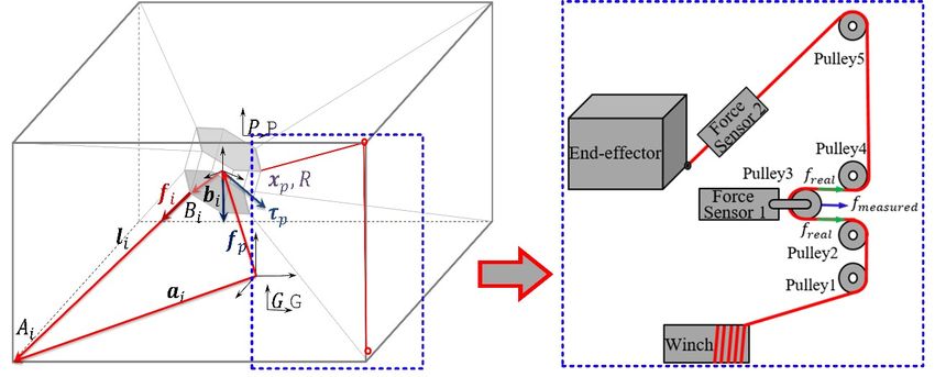
Sensors 2019, 19, 2520                                                                            2 of 16

end-effector, the number of cables must be higher than the necessary number of end-effector’s
degrees-of-freedom (DOF). Based on the number of cables (m) and number of DOFs (n), CDPRs can
be classified into: Under-constrained type (m < n) and fully-constrained type (m ≥ n + 1) [4]. Amongst
these, the fully-constrained CDPR is essential for implementing full 6-DOF robotic motion. However,
the fully-constrained CDPR has infinite tension distribution for any given spatial posture of the end-
effector, and its kinematic structure matrix depends strongly on the pose of the end-effector in the
parallel robotic mechanism. This brings forth another important issue as to how all the actuating
cables can be maintained at the proper tension levels by considering the redundant kinematic
constraints, to avoid sagging of cables or overloading; that is, eventually, for the CDPR force control.
      Several force-distribution algorithms [5–7] were previously utilized for CDPR motion control
and cable-tension control [8–10]. However, even with these force-distribution algorithms, the CDPR
force control was challenging, in practice. One main reason was the difficulty of measuring the direct
force distributions at the end-effectors, because of the friction between the cables and pulleys [11].
Friction modeling and compensation methods have been widely studied for robot systems, and some
methods were proposed for cable–pulley friction models in the CDPR. With the assumption of no-
slip at the cable and pulley interface, Choi et al. modeled the pulley bearing friction based on the
Dahl friction, to estimate cable tensions during slow motion [12]. Kraus et al. implemented pulley
friction compensation using the Coulomb and Dahl friction model. They also analyzed the influence
of friction on the wrench measurement and pointed out that pulley friction influenced the wrench
hysteresis significantly [11]. Peng et al. used a multibody dynamic approach to model the friction of
the cable–pulley system. The model considered the friction of the sliding joint, using the arbitrary
Lagrangian–Eulerian formulation [13]. In addition, for a diverse range of mechanical systems
requiring accurate positioning and force control, many research has addressed the pulley friction
effect on the cable–pulley structured mechanisms [14–17].
      The CDPR friction between the cable and pulley is influenced by the pulley bearing friction,
sliding friction, and friction among other mechanical parts. In this context, it can be stated that most
of the traditional-model-based friction estimations, used in the previous research, represented only
part of the friction phenomena. Moreover, the previous methods experienced difficulties in
identifying the model parameters, especially for dynamic models because of the nonlinearity and
long-term variations of properties due to abrasion [18]. Moreover, in addition to pulley friction, the
cable elongation and its nonlinear properties also caused tension discrepancies for the cable
connection from each winch to the end-effector. Therefore, a more complicated model for accurate
tension estimation is necessary.
      In this paper, we propose an artificial neural network (ANN)-based indirect end-effector force-
estimation method, and design a proportional CDPR force-control algorithm that can compensate for
the inaccurate measurements of the CDPR end-effector force and achieve indirect force control for
CDPR. We consider the pulley friction and unmodeled cable effects as a black-box uncertainty. The
estimated cable tension of the end-effector compensates for this uncertainty by using an ANN model
that is derived from the training datasets of the CDPR experiments. In order to implement an efficient
ANN model, we obtain the parameters affecting the friction in a CDPR based on the traditional
friction model. Then, the ANN model is trained by spatial motion experiments conducted for the
given trajectories that cover the desired motion ranges of the end-effector. The MATLAB ANN
toolbox is used to design an ANN estimator, which is implemented in real-time using PLC
structured-text programming. The effectiveness of the proposed ANN model is evaluated based on
the cable force control achieved in the CDPR system.
      It is well known that ANNs have the capability to approximate nonlinear functions through
learning processes [19–22], and they were previously applied for friction compensation, as follows.
Huang et al. used two neural network (NN) approximators to design an intelligent controller for
compensating the effect of nonlinear friction in a 1-DOF mechanical system [23]. Guo et al. proposed
an NN structure with additional jump approximation activation functions to model the complex and
discontinuous friction dynamics for a six-axis articulated robot tracking control [24]. Liu et al. used
an NN-based friction compensation method for approximating the residual values during free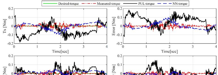
Sensors 2019, 19, 2520 3 of 16
motion [25]. Several other friction compensation techniques using ANNs could be found in the
previous research [26–28]. Nevertheless, to the best of the authors’ knowledge, our study is the first
ANN application to use the cable force control of a CDPR by using an ANN-based CDPR end-
effector’s cable tension estimator for estimating the cable–pulley friction and compensating for cable
uncertainties.
The outline of this paper is as follows. Section 2 introduces the laboratory-scale CDPR, which is
employed in this study, and explains the robot kinematics and dynamics. Section 3 describes the
friction effects in the cable–pulley compartments and provides an ANN-model-based friction-
compensation method. In Section 4, the force and position control algorithms based on ANN are
explained. Section 5 shows the experimental results of the ANN-based cable force control in a Mini
CDPR. Finally, we conclude this paper in Section 6.
2. CDPR system
2.1. MINI CDPR
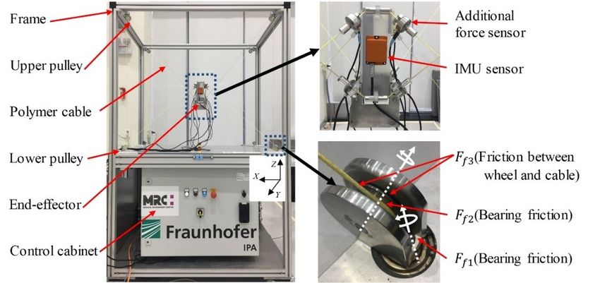
The lab-scale Mini CDPR employed in this work is shown in Figure 1. It is a type of fully-
constrained 6-DOF CDPR, which is actuated by eight polyethylene Dyneema® cables (LIROS D-Pro
01505-0200, 2 mm). The robot uses industrial servo drives and controllers as hardware, and
TwinCAT3 is used as the real-time control software [29]. The size of the fixed frame is 1.10 m × 0.80
m × 0.95 m, and the mass of the end-effector is 1.42 kg. Force sensors (Micro Load Cell - CZL635 up
to 50 N) for cable force measurements are integrated with each guiding pulley at the winch motors
at the bottom of the CDPR frame. This mechanism can prevent the interferences from additional
sensors, to the end-effector movement. However, the cable force measurements are always affected
by the friction between the winch and the end-effector.
Figure 1. Photograph of the MINI cable robot and its cable connection components.
In this study, in order to obtain the gold-standard force distribution of the end-effector, eight
additional force sensors (UMM-K10 up to 100 N) are connected directly to the end-effector for
reference measurements. It should be pointed out that the additional force sensors are installed only
for the friction and uncertainty identification and ANN training.
2.2. Force Sensor Calibration
Each force sensor must be calibrated, to avoid unnecessary issues arising from the
manufacturing variations and/or influence of the operating environment. In order to achieve the best
possible accuracy, we perform two types of calibration approaches: Calibration without pulley and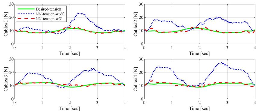
Sensors 2019, 19, 2520                                                                                           4 of 16

calibration with pulley. In the former approach, the force sensor is calibrated directly by attaching
known weights; in the latter, the force sensor is combined with a cable pulley system and is calibrated
by attaching known weights. The performances of the calibrations are compared with the
experimental results, as shown in Figure 2. According to the wiring mechanism of the pulley in Figure
3b, the measured value from force sensor 1 is half of the real cable tension. In the case of calibration
with a pulley, hysteresis is observed between the loading and unloading processes. Furthermore, the
maximum error is approximately 1.5 N, which is 6% of the actual cable tension capacity. On the other
hand, for the calibration without pulley, very good accuracy is observed, as the system is not
influenced by pulley friction. Hence, all the force sensors are calibrated without using pulleys to
obtain pure tension values.

                                                        (a)

                                                        (b)
      Figure 2. Force sensor calibration results: (a) Calibration without pulley; (b) calibration with pulley.

2.3. Kinematics and Dynamics
     Figure 3a shows a schematic of the fully-constrained CDPR, where the index denotes the cable
number. The geometric parameter        is a cable-attaching point on the base frame and    is a cable-
attaching point on the end-effector.     and     are two constant vectors of the base coordinate { }
and end-effector coordinate { }, respectively. The inverse kinematics are used to describe the joint
variables from the given end-effector posture [30]. Hence, based on the closure vector loop, the cable
length vector    can be described as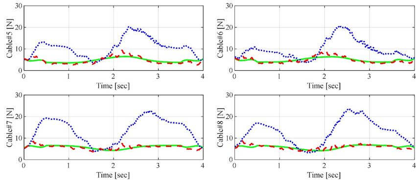
Sensors 2019, 19, 2520                                                                              5 of 16

                          (a)                                                    (b)
      Figure 3. Description of the robot geometry: (a) Kinematic and dynamic notation of cable-driven
      parallel robot (CDPR); (b) cable pulley system.

                                            =       −       −                                           (1)
where      and     describe the end-effector position and orientation, respectively.
     In Figure 3a,    denotes the cable force vector along the -th cable, while the external force
and torque     act on the end-effector. The force and torque equilibrium at the end-effector yields

                                                    +       =                                           (2)

                                                (       × )+            =                               (3)

where =        with the obtained unit vector being       = ⁄‖ ‖. From Equations (2) and (3), the
equilibrium equation can be written in the matrix form as follows.

                                        ⋯
                                                                    ⋮   +    =                          (4)
                                 ×      ⋯           ×

which can be expressed in a more compact form as below:
                                                ,       +       =                                       (5)
where      is an external wrench force applied at the end-effector. Here, the transpose of the Jacobian
matrix      is called the structure matrix. The standard dynamic equation of the CDPR, assuming that
all the cables are tensioned, can be obtained from Equation (5), in the global coordinate of the robot
system, as follows [31].
                                ( ) ̈ + ( , ̇) ̇ +      +       ( , ̇) = −                              (6)
where ( ) is the inertia matrix of the robot, ( , ̇ ) is the vector of Coriolis and centripetal terms,
 is the vector of gravity terms, and   ( , ̇ ) is the friction term in the system.

3. ANN-Based Cable Tension Estimation
     An ANN is a generalized model of the biological nervous system, which is based on the brain
function, to obtain the knowledge. It has the ability to learn effectively from data, and compute
nonlinear problems. The main advantage of the ANN model is that it can be implemented easily
without complicated mathematical modeling and parameter identification. As the traditional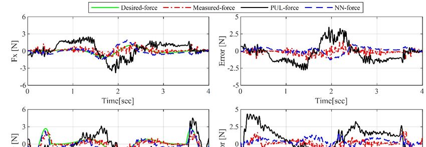
Sensors 2019, 19, 2520                                                                             6 of 16

methods often experience difficulty in modeling complicated nonlinear behavior, intelligent ANN-
based friction compensation is designed in this study.

3.1. Friction Model Revisited
     In CDPR, accurate measurement of the force distribution of the end-effector is essential to
achieve CDPR force control. However, the measured tensions are influenced by the friction between
the force sensor and end-effector and cable effects along the wiring. In the Mini CDPR, five pulleys
are used to guide cables to the end-effector and the force sensor is equipped at pulley3, as illustrated
in Figure 3b. The friction between the force sensor 1 and end-effector can be divided into two parts,
pulley bearing friction and sliding friction. In Figure 1,     is the sliding friction between the cable
and wheel.       and       describe two different pulley bearing frictions.     is caused by the rotation
of the pulley and       is due to the rotation of the wheel.
     The basic model to describe the above friction is a combination of the Coulomb friction and
linear viscous friction models. It is mathematically given by:
                                       ( )=            ( )+                                           (7)
where      is the normal force.       and    are the Coulomb friction coefficient and viscous friction
coefficient, respectively. This model exhibits easy implementation, but leads to poor performance,
especially in the case of friction at low velocities.
     The Dahl model is a simple model to simulate ball-bearing friction. This model is a function of
the displacement , which makes it possible to estimate the hysteresis behavior of the friction [11]:

                            ( )
                                  =   1−        ( ̇)          1−        ( ̇)                          (8)

where σ is the stiffness parameter at an equilibrium point,       is the Coulomb friction, and is a
material-dependent parameter. The Dahl model can produce a smooth transition around zero
velocity, but fails to describe the stiction and Stribeck effect.
     Despite these traditional models, many complex models have been proposed to describe the
nonlinear behavior of friction, such as the Karnopp model, Leuven model, and seven parameters
model [32]. However, these models present complexities during mathematical modeling and
identification of parameters. Instead, we utilized the traditional models, which is revisited in this
section, to obtain the key parameters while designing the ANN models used in this study.

3.2. Designing and Training the ANN
      By considering a characteristic of the CDPR that has the capability in large translational motion
but limited rotational motion, we only consider the translational motion in this paper. In order to
design and train the proposed neural network, a number of inputs and known outputs are necessary.
The input values should be eight measured tensions near the pulleys (PUL-tension) and the output
values are eight measured reference tensions near the end-effector (EE-tension). However, one type
of input value is not sufficient to output the desired tension because of the hysteresis and nonlinear
behavior of friction during dynamic motion. From Equation (7) and (8) of the traditional pulley
friction models, we can see that      ,    , and     are related to the cable length, cable velocity, and
pulley wrapping angle, respectively. Therefore, these variables are included in the ANN model. The
bearing friction     is dependent on the position and velocity of the end-effector. The cable length,
cable velocity, and pulley wrapping angle are also dependent on the position and velocity of the end-
effector. Hence, we add the position and velocity of the end-effector as additional inputs. The design
of the ANN structure is described in Figure 4. In total, 14 inputs and 8 outputs are incorporated in
the ANN to compensate for the cable tension discrepancy between the measurements at the winch
side and end-effector; the inputs are [ , ⋯ , ] =          ,   ,   , ̇ , ̇ , ̇ ,      ,⋯,        and the
outputs are [ , ⋯ , ] = [       ,⋯,      ]. The output of the designed ANN is computed as follows: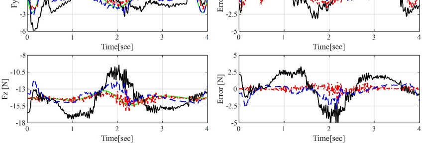
Sensors 2019, 19, 2520                                                                                              7 of 16

                                               =                     +                                                  (9)

where the sigmoid activation functions are                       = 1/ 1 +                 and         =                  +
   .

                            Figure 4. Proposed structure of the artificial neural network.

    To obtain an acceptable range of training data, we operate the robot with a predefined trajectory.
The training trajectory is a translation motion in space, which includes four straight paths along a
diagonal line of cubic space and three circular paths (xy plane, xz plane, and yz plane), as shown in
Figure 5.

                             (a)                                                          (b)
       Figure 5. Training trajectories (blue line) and test trajectories (red dot line) for artificial neural network
       (ANN) model evaluation: (a) Test trajectory 1: A three-dimensional circular path and one straight line
       in the y-direction; (b) test trajectory 2: Line paths that connect 20 arbitrary points where the test
       trajectories are identical.

    We use the MATLAB Toolbox (MathWorks, USA) to create an ANN. In the present study, the
Bayesian regularization method is used for friction compensation because this algorithm can produce
good generalization for difficult, small, or noisy datasets. It is a two-layer feed-forward network,
which consists of sigmoid hidden neurons and linear output neurons to fit the input and output.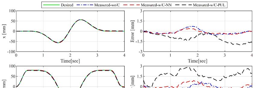
Sensors 2019, 19, 2520                                                                               8 of 16

3.3. Performance Evaluation of ANN
     Once the ANN has been trained for satisfactory performance, it is tested for performance
validation in compensating for the friction in real-time. For the validation, we connect additional
force sensors to each cable at the end-effector side, which measure the actual end-effector cable
tension (EE-tension), as shown in Figure 1. To evaluate the proposed ANN model, the tension
measured by the pulley-integrated force sensor (PUL-tension) at the winch side and the end-effector
tension estimated via the ANN (NN-tension) are compared with the tension measured at the end-
effector (EE-tension) while operating the robot along two kinds of test trajectories, which are different
from the training trajectory. The first trajectory is composed of a three-dimensional circular path and
one straight line in the y-direction, as shown in Figure 5a. This trajectory is used to evaluate the whole
performance of ANN in this paper. The second trajectory is line paths, which connect 20 arbitrary
points in the training workspace, as shown in Figure 5b, which for the evaluation of the general case.
The root mean square errors (RMSE) between the measured PUL-tension and measured EE-tension
and between the compensated NN-tension and measured EE-tension, for the eight cable tensions,
are listed in Tables 1 and 2. In Figure 6, the PUL-tension, NN-tension, and EE-tension for a single
cable (cable #2, test trajectory 1), and their errors, are plotted. It is observed that the PUL-tension and
EE-tension are mismatched because of the uncertainty and pulley friction. In cable #2, the maximum
error between the measured tension, PUL-tension, and realistic distributed tension, EE-tension, is
approximately ±4 N. Furthermore, in the eight cables, the RMSE in test trajectory 1 is approximately
2 N and the RMSE in test trajectory 2 is approximately 1.5 N. On the other hand, the tension values,
which are compensated by the neural network (NN-tension), are very close to the actual end-effector
cable tension, EE-tension. The mean value of the RMSE between NN-tension and EE-tension is
approximately 0.5 N. Hence, we can confirm that the trained ANN force-discrepancy-compensation
model can estimate the cable force distribution of the end-effector successfully.

      Table 1. Root mean square error (RMSE) between measured EE-tension (end-effector tension
      measurements), measured PUL- tension (winch-motor-side tension measurements), and estimated
      NN-tension (end-effector tension estimated by ANN) in test trajectory 1.

                      [ ]                                                                 mean
                 EE-tension vs.
                                  1.81   2.11   2.02   2.77   1.89   1.69   1.81   1.82
                  PUL-tension                                                             1.99
                   EE-tension
                       vs.        0.82   0.46   0.42   0.65   0.34   0.44   0.64   0.30
                                                                                          0.51
                  NN-tension

      Table 2. Root mean square error (RMSE) between measured EE-tension (end-effector tension
      measurements), measured PUL- tension (winch-motor-side tension measurements), and estimated
      NN-tension (end-effector tension estimated by ANN) in test trajectory 2.

                      [ ]                                                                 mean
                 EE-tension vs.
                                  1.34   1.54   1.30   1.41   1.63   1.57   1.31   1.50
                  PUL-tension                                                             1.45
                   EE-tension
                       vs.        0.52   0.51   0.65   0.48   0.38   0.67   0.36   0.73
                                                                                          0.54
                  NN-tension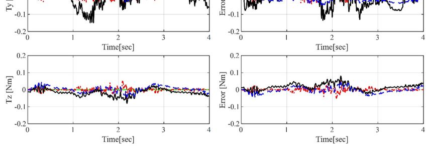
Sensors 2019, 19, 2520                                                                                   9 of 16

                          (a)                                                   (b)

      Figure 6. Comparison results of cable tension during movement along test trajectory 1: (a) Tension
      comparison among the measured EE-tension, PUL-tension, and compensated NN-tension; (b)
      tension error comparison: PUL-tension versus EE-tension and NN-tension versus EE-tension.

4. End-Effector Force Control
      The CDPR force controller based on the ANN end-effector cable-tension estimation is designed
for end-effector force tracking, with respect to the predefined cable tensions, as the end-effector
moves along the planned trajectory. A block diagram of the proposed force-control algorithm
utilizing the ANN cable tension estimation is shown in Figure 7. The position of the CDPR is
determined by an open-loop position control mechanism and the force of the end-effector is
determined by a closed-loop cable tension control mechanism. The open-loop position control is
derived by using the inverse kinematics of the CDPR to obtain the desired cable length      for the
given desired position    , as expressed in Equation (1).

        Figure 7. Block diagram of the proposed force control algorithm using the ANN force estimator.

     In the fully-constrained CDPR, infinite force-distribution solutions exist because of the non-
square structure matrix. Hence, it is necessary to find a suitable range of force distributions, to
improve the performance of the CDPR, e.g., to prevent sagging or minimize tension efforts. In this
work, we utilized a closed-form solution to calculate the required cable forces [8], to find continuous
force distributions quickly, in real time. This algorithm uses the Moore–Penrose matrix inverse
to obtain the least-square optimal solution. For the given wrench,     , the desired cable force can be
generated as
                                           =       −          +                                            (10)
where        is the reference cable force. It helps the cable force distribution to be bound in the
specified range. However, this formula has a limitation on finding whole feasible solutions. It might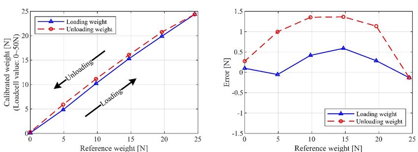
Sensors 2019, 19, 2520                                                                                       10 of 16

fail to provide feasible solutions when close to the border of the wrench-feasible workspace. In this
case, an improved force distribution algorithm can be applied to find feasible solutions [33]. In this
study, the operating workspace is initially designed by a calculation from the feasible closed form
solution, then the feasible solutions are guaranteed at any posture inside the workspace.
      While moving, the cable tensions are measured by the force sensors equipped at each winch
pulley. However, as the measured PUL-tension,            , is different from the actual end-effector force
because of uncertainty and cable–pulley friction, we utilize the estimated NN-tension,           , from the
designed ANN as a force-feedback signal. A simple P-controller is implemented to control the tension
error between the desired tension and NN-tension. In Figure 7,             is each cable’s tension control
input, which is defined as      = ( −          ). As stated earlier,        is obtained to compensate for
the tension discrepancy between the measured tension (PUL-tension) and actual distributed tension
(EE-tension) at the end-effector. If we assume that         can estimate the actual end-effector tension,
then the wrench input can be expressed as follows

                         −   ≅−           +       (       −        ) + ( , ̇) ̇ +     ( , ̇)                    (11)

where      is a position-control input to the CDPR. By utilizing Equation (11), the CDPR force-
control model can be simplified as follows

                               ( ) ̈ =−                   +   (      −       ) −                                (12)

where       is a servo portion of the controller in CDPR, and we consider it in the Cartesian space as
−        =       ̇+      . Then, the servo portion is obtained by      =       ̇ +         , so we can
derive the relationship between Cartesian space and Joint space as           ̇+      =−           ̇ +
        , where         and        are proportional and derivative (PD) parameters in joint space,
respectively. Thus, we can obtain the following error dynamics for the CDPR system:
                                               ( ) ̈+              ̇+

                                         =                    −              +         −       +   ( ) ̈ +      (13)

                                         =
where          = and     = ( ) ̈ + .
     Let us define a Lyapunov candidate as V = 1/2( + ̇ ), which is positive definite. The
derivative of the Lyapunov function can be negative definite, according to the LaSalle’s invariance
principle as follows.
                                              V̇ =        ̇+ ̇ ̈

                                                  =       ̇+ ̇           −       ̇−                             (14)

                                                  =− ̇                  ̇ ≤0
Hence, the asymptotic stability of the designed controller can be verified.
    Finally, the input tension to the CDPR is conveyed to the cable length input through the winch
motor. We use the linear stiffness model to transfer the cable force to the cable length, as follows

                                              ∆       =                                                        (15)

where    is the elastic modulus,    is the actual cross-sectional area, and                    is the cable length
between each winch and the attaching point of the end-effector.

5. Experimental Results
     The CDPR force control is performed using the proposed control scheme, as shown in Figure 7,
in the test trajectory 1. We use original factory setting values of the control gain =      [0.015]
and       =        [0.125] (drive model: EL7201-BECKHOFF). In the case of cable force control, the P
Sensors 2019, 19, 2520 11 of 16
gain ( = [0.70]) is tuned manually and selected by the sensitivity analysis as listed in Table 3.
In order to evaluate the performance of cable tension control in the wrench space, in addition to the
additional force sensors along the cable at the end-effector side, an inertia measuring unit (IMU)
sensor (MTI-300, Netherlands) is assembled at the end-effector, which can measure the actual end-
effector force during the experiments. In Figure 8, the force and torque applied to the end-effector are
expressed in four ways, where the desired force and torque are calculated with the given
accelerations, based on Equation (6). Simultaneously, the measured-force and torque are obtained
from the IMU sensor measurements. In the results, PUL-force and PUL-torque are the calculated
force and torque from the measured PUL-tension, and NN-force and NN-torque are obtained from
the estimated NN-tension via ANN. Furthermore, the RMSEs between Desired-wrench and
Measured-wrench, Desired-wrench and NN- wrench, and Desired-wrench and PUL-wrench are listed
in Table 4.
Table 3. Force error sensitivity analysis (all cables have the same gain) with respect to the gain
variation.
kp 0.55 0.60 0.65 0.70 0.75 0.85 0.90
RMSE [N] 0.489 0.466 0.465 0.437 0.451 0.479 0.527
Table 4. Root mean square error (RMSE) between Desired-wrench, Measured- wrench, NN- wrench, and
PUL- wrench.
[ ] [ ] [ ] [ ] [ ] [ ]
Desired-wrench vs. Measured-wrench 0.42 0.61 0.37 0.01 0.01 0.01
Desired-wrench vs. NN-wrench 0.44 0.56 0.80 0.03 0.02 0.02
Desired -wrench vs. PUL-wrench 1.36 1.90 1.87 0.09 0.05 0.03
The experimental results show that the actual end-effector force obtained by both the IMU sensor
and ANN algorithm follow the desired force references within acceptable ranges. However, the PUL-
force shows poor performance in the wrench space, compared to both the IMU sensor measurements
and desired force. This is because of the tension discrepancy between the realistic distributed tension
(EE-tension) and measured PUL-tension from the winch side. This result emphasizes the fact that
the use of uncompensated tension measurements to control the robot can lead to undesirable
performances. If the test trajectory involves only translation motion, the desired orientation motion
and torque value will be zero. In the case of applications such as pick and place, which only require
translation motion and force, unwanted orientation motion and torque may influence the
performance of the robot. Hence, the orientation and torque accuracy are analyzed as well, from these
experiment results. We also verify the performance of the proposed ANN algorithm; the torque
measurements from the IMU sensor and the NN-torque from the estimated NN-tension are very
close, with RMSE less than 0.03 Nm, which can be considered as sensor noise.
To evaluate the position trajectory tracking performance, a precise 6-DOF displacement
measurement sensor, OTS (optical track sensor, Model: Polaris Spectra from NDI® with RMS of 0.3
mm at 60 Hz) is utilized. In Figure 9, the position and orientation accuracy are compared for the cases
of without cable force control, with NN-tension-based force control, and with PUL-tension-based
force control. In the case of without force control and with NN-tension-based force control, the
position errors are less than 1 mm and orientation errors are less than 0.6°. However, the position and
orientation errors of PUL-tension-based force control are quite large. These results show that
inaccurate cable tension distribution can be affecting the balance of the end-effector, which lead to
the inaccurate performance of the robot.Sensors 2019, 19, 2520 12 of 16
(a)
(b)
Figure 8. Results of cable force control in terms of (a) force and force errors; and (b) torque and torque
errors.Sensors 2019, 19, 2520 13 of 16
(a)
(b)
Figure 9. Comparison of position and orientation accuracy, with and without cable force control: (a)
Positions and position errors; (b) orientations and orientation errors. Measured-wo/c: Measured
position and orientation without force control, measured-w/C-NN: Measured position and
orientation with force control based on the estimated NN-tension, measured-w/C-PUL: Measured
position and orientation with force control based on the measured PUL-tension.Sensors 2019, 19, 2520 14 of 16
Figure 10 shows the CDPR cable tension comparison during force-control experiments: NN-
tension without force control and NN-tension with force control. When cable force control is not
applied, the cable tension changes over a wide range. The cable tension in cable #4 is greater than 25
N, which is out of the accurate range of the force sensor measurement. However, when we apply the
proposed cable tension control, the actual cable tension follows the desired tension. This is a strong
proof that the proposed ANN-based end-effector cable-tension estimation and force-control scheme
can control the individual cable tensions within certain bounds of desired tension ranges, which can
prevent sagging or overloading during movement.
Figure 10. Comparison of cable tension in cable-driven parallel robot (CDPR) with and without cable
force control. NN-tension-wo/C: Compensated neural network tension without force control during
motion; NN-tension-w/C: Compensated neural network tension with force control during the motion.
6. Conclusions
In this paper, we presented an ANN-based end-effector force estimation method to compensate
for the uncertainties including cable–pulley friction and nonlinear cable behavior that created tension
discrepancies between the tensions measured at the winch side and end-effector. The proposed ANN
model designed by position and velocity measurements could estimate the force distribution of the
end-effector, accurately, from the available tension measurements at the winch pulley side. The
performance of the designed ANN model was verified by the experimental results for ANN model
validation and CDPR end-effector force control. The results showed that the estimated end-effector
force from the designed ANN model could overcome the cable tension discrepancies caused by
uncertainties in the force transmission to the end-effector from the winch motor. Moreover, the
measured force distributions in the time domain were very close to the actual values and could be
applied to the CDPR force controller as cable tension feedback. Finally, the proposed method couldSensors 2019, 19, 2520 15 of 16
control the cable tensions within the desired range, which could prevent sagging and minimize the
required tension energy. In the future, the developed method can be implemented in grand CDPR
systems designed for handling heavy loads. An advanced control algorithm for a force and position
hybrid controller will be developed to enhance the application of CDPR in the industry.
Author Contributions: All authors contributed to this study presented in the manuscript. Methodology: J.P. and
E.-S.K.; investigation: E.-S.K., E.C., and C.M.; writing—original draft preparation: J.P. and C.-S.K.; writing—
review and editing: J.-O.P., H.C., and C.-S.K.; supervision: J.-O.P. and C.-S.K.
Funding: This research was supported by the Leading Foreign Research Institute Recruitment Program through
the National Research Foundation of Korea (NRF) funded by the Ministry of Science, ICT & Future Planning
(MSIF) (2012K1A4A3026740).
Conflicts of Interest: The authors declare no conflicts of interest.
References
1. Li, H.; Yao, R. Optimal Orientation Planning and Control Deviation Estimation on FAST Cable-Driven
Parallel Robot. Adv. Mech. Eng. 2014, 6, 716097.
2. Qian, S.; Bao, K.; Zi, B.; Wang, N. Kinematic Calibration of a Cable-Driven Parallel Robot for 3D Printing.
Sensors 2018, 18, 2898.
3. Su, Y.; Qiu, Y.; Liu, P. Optimal Cable Tension Distribution of the High-Speed Redundant Driven Camera
Robots Considering Cable Sag and Inertia Effects. Adv. Mech. Eng. 2014, 6, 729020.
4. Abbasnejad, G.; Eden, J.; Lau, D. Generalized Ray-Based Lattice Generation and Graph Representation of
Wrench-Closure Workspace for Arbitrary Cable-Driven Robots. IEEE Trans. Robot. 2019, 35, 147–161.
5. Song, D.; Zhang, L.; Xue, F. Configuration Optimization and a Tension Distribution Algorithm for Cable-
Driven Parallel Robots. IEEE Access 2018, 6, 33928–33940.
6. Gouttefarde, M.; Lamaury, J.; Reichert, C.; Bruckmann, T. A Versatile Tension Distribution Algorithm for
n-DOF Parallel Robots Driven by n+2 Cables. IEEE Trans. Robot. 2015, 31, 1444–1457.
7. Pott, A.; Bruckmann, T.; Mikelsons, L. Closed-form Force Distribution for Parallel Wire Robots. In
Computational Kinematics; Springer: Berlin, Germany, 2009; pp. 25–34.
8. Kraus, W.; Schmidt, V.; Rajendra, P.; Pott, A. System identification and cable force control for a cable-driven
parallel robot with industrial servo drives. In Proceedings of the 2014 IEEE International Conference on
Robotics and Automation (ICRA), Hong Kong, China, 31 May–7 June 2014; pp. 5921–5926.
9. Jun, J.; Jin, X.; Pott, A.; Park, S.; Park, J.-O.; Ko, S.Y. Hybrid position/force control using an admittance
control scheme in Cartesian space for a 3-DOF planar cable-driven parallel robot. Int. J. Control Autom. Syst.
2016, 14, 1106–1113.
10. Xiong, H.; Diao, X. Cable tension control of cable-driven parallel manipulators with position-controlling
actuators. In Proceedings of the 2017 IEEE International Conference on Robotics and Biomimetics (ROBIO),
Macau, China, 5–8 December 2017; pp. 1763–1768.
11. Kraus, W.; Kessler, M.; Pott, A. Pulley friction compensation for winch-integrated cable force measurement
and verification on a cable-driven parallel robot. In Proceedings of the 2015 IEEE International Conference
on Robotics and Automation (ICRA), Seattle, WA, USA, 26–30 May 2015; pp. 1627–1632.
12. Choi, S.-H.; Park, J.-O.; Park, K.-S. Tension analysis of a 6-degree-of-freedom cable-driven parallel robot
considering dynamic pulley bearing friction. Adv. Mech. Eng. 2017, 9, doi:10.1177/1687814017714981.
13. Peng, Y.; Wei, Y.; Zhou, M. Efficient modeling of cable-pulley system with friction based on arbitrary-
Lagrangian-Eulerian approach. Appl. Math. Mech. 2017, 38, 1785–1802.
14. Miyasaka, M.; Matheson, J.; Lewis, A.; Hannaford, B. Measurement of the cable-pulley Coulomb and
viscous friction for a cable-driven surgical robotic system. In Proceedings of the 2015 IEEE/RSJ International
Conference on Intelligent Robots and Systems (IROS), Hamburg, Germany, 28 September–2 October 2015;
pp. 804–810.
15. Yu, L.; Wang, Z.; Wang, W.; Li, H.; Wang, L. Research on micromanipulator’s clamping force sensing based
on static wirerope tension of a surgical robot. Adv. Mech. Eng. 2015, 7, doi:10.1177/1687814015581246.
16. Lee, T.-K.; Kim, C.-Y.; Lee, M.C. Friction analysis according to pretension of laparoscopy surgical robot
instrument. Int. J. Precis. Eng. Manuf. 2011, 12, 259–266.
17. Xue, R.; Du, Z.; Yan, Z.; Ren, B. An estimation method of grasping force for laparoscope surgical robot
based on the model of a cable-pulley system. Mech. Mach. Theory 2019, 134, 440–454.Sensors 2019, 19, 2520 16 of 16
18. Ismaila, T.; Akmeliawati, R.; Salami, M.J.E. Artificial Intelligent Based Friction Modelling and
Compensation in Motion Control System. Adv. Mech. 2011, 43–68.
19. De Araújo, J.M.; de Menezes, J.M.P.; Moura de Albuquerque, A.A.; da Mota Almeida, O.; Ugulino de
Araújo, F.M. Assessment and certification of neonatal incubator sensors through an inferential neural
network. Sensors 2013, 13, 15613–15632.
20. Jung, S. Stability analysis of reference compensation technique for controlling robot manipulators by neural
network. Int. J. Control Autom. Syst. 2017, 15, 952–958.
21. Shin, J.; Kim, S.; Tsourdos, A. Neural-networks-based Adaptive Control for an Uncertain Nonlinear System
with Asymptotic Stability. Int. J. Control Autom. Syst. 2018, 16, 1989–2001.
22. Chen, H.-G.; Wang, Y.-H.; Zhang, L.-L. Adaptive Control based on Extended Neural Network for SISO
Uncertain Nonlinear Systems. Int. J. Control Autom. Syst. 2018, 16, 27–38.
23. Huang, S.; Tan, K.K. Intelligent Friction Modeling and Compensation Using Neural Network
Approximations. IEEE Trans. Ind. Electron. 2012, 59, 3342–3349.
24. Guo, K.; Pan, Y.; Yu, H. Composite Learning Robot Control with Friction Compensation: A Neural
Network-Based Approach. IEEE Trans. Ind. Electron. 2018, doi: 10.1109/TIE.2018.2886763.
25. Liu, X.; Zhao, F.; Ge, S.S.; Wu, Y.; Mei, X. End-Effector Force Estimation for Flexible-Joint Robots With
Global Friction Approximation Using Neural Networks. IEEE Trans. Ind. Inf. 2019, 15, 1730–1741.
26. Lin, C.-H. Precision Motion Control of a Linear Permanent Magnet Synchronous Machine Based on Linear
Optical-Ruler Sensor and Hall Sensor. Sensors 2018, 18, 3345.
27. Echávarri Otero, J.; de la Guerra Ochoa, E.; Chacón Tanarro, E.; Lafont Morgado, P.; Díaz Lantada, A.;
Munoz-Guijosa, J.M.; Muñoz Sanz, J.L. Artificial neural network approach to predict the lubricated friction
coefficient. Lubr. Sci. 2014, 26, 141–162.
28. Hu, J.; Wang, Y.; Liu, L.; Xie, Z. High-accuracy robust adaptive motion control of a torque-controlled motor
servo system with friction compensation based on neural network. Proc. Inst. Mech. Eng. Part C J. Mech. Eng.
Sci. 2019, 233, 2318–2328.
29. Jin, X.; Jung, J.; Ko, S.; Choi, E.; Park, J.-O.; Kim, C.-S. Geometric Parameter Calibration for a Cable-Driven
Parallel Robot Based on a Single One-Dimensional Laser Distance Sensor Measurement and Experimental
Modeling. Sensors 2018, 18, 2392.
30. Jin, X.; Jung, J.; Piao, J.; Choi, E.; Park, J.-O.; Kim, C.-S. Solving the pulley inclusion problem for a cable-
driven parallel robotic system: Extended kinematics and twin-pulley mechanism. J. Mech. Sci. Technol. 2018,
32, 2829–2838.
31. Khosravi, M.A.; Taghirad, H. Dynamic analysis and control of cable driven robots with elastic cables. Trans.
Can. Soc. Mech. Eng. 2011, 35, 543–557.
32. Marques, F.; Flores, P.; Pimenta Claro, J.C.; Lankarani, H.M. A survey and comparison of several friction
force models for dynamic analysis of multibody mechanical systems. Nonlinear Dyn. 2016, 86, 1407–1443.
33. Pott, A. An Improved Force Distribution Algorithm for Over-Constrained Cable-Driven Parallel Robots. In
Computational Kinematics; Springer: Dordrecht, The Netherlands, 2014; pp. 139–146.
© 2019 by the authors. Licensee MDPI, Basel, Switzerland. This article is an open access
article distributed under the terms and conditions of the Creative Commons Attribution
(CC BY) license (http://creativecommons.org/licenses/by/4.0/).You can also read