Installation regulations - Flair 325 English - Brink Climate Systems
←
→
Page content transcription
If your browser does not render page correctly, please read the page content below
Installation regulations
Flair 325
English
Installation regulations
                          Heat recovery appliance

                                 Flair 325 Plus

                          Store near the appliance

This appliance may be used by children as of 8 years of age, persons with reduced
physical or mental capacities, and persons with limited knowledge and experience if
they are supervised or have received instructions on how to use the appliance safely
and are aware of the possible dangers.
Children younger than 3 years of age must be kept away from the appliance, unless
they are under constant supervision.
Children between the ages of 3 and 8 may only switch the appliance on or off, but only if
supervised or if they have received clear instructions on the safe use of the appliance
and understand the possible dangers, on the condition that the appliance has been
placed and installed in the normal position for use. Children between the ages of 3 and
8 may not insert the plug into the socket, nor clean or make changes to the settings of
the appliance, nor carry out any maintenance on the appliance that would normally be
carried out by the user. Children may not play with the appliance.
If you need a new power cable, always order the replacement from Brink Climate
Systems B.V. To prevent dangerous situations, a damaged mains connection must only
be replaced by a qualified expert!

                                  Country: GB
Contents
1 Delivery. . . . . . . . . . . . . . . . . . . . . . . . . . . . . . . . . . . . . . . . 5 11.1.4 Connecting extra multiple switch with filter
1.1 Delivery size. . . . . . . . . . . . . . . . . . . . . . . . . . . . . . . . . 5 indication. . . . . . . . . . . . . . . . . . . . . . . . . . . . . . . . . . 41
2 General. . . . . . . . . . . . . . . . . . . . . . . . . . . . . . . . . . . . . . . . . 6 11.2 Connecting Brink Air Control. . . . . . . . . . . . . . . . . 42
3 Version. . . . . . . . . . . . . . . . . . . . . . . . . . . . . . . . . . . . . . . . . 7 11.3 Connecting humidity sensor. . . . . . . . . . . . . . . . . 43
3.1 Technical information. . . . . . . . . . . . . . . . . . . . . . . . . 7 11.4 Connecting CO₂ sensor(s). . . . . . . . . . . . . . . . . . . . 44
3.2 Connections and dimensions. . . . . . . . . . . . . . . . . . . 8 11.5 Demand-driven ventilation 2.0. . . . . . . . . . . . . . . 45
3.3 Exploded view of appliance. . . . . . . . . . . . . . . . . . . 10 11.6 Connecting postheater. . . . . . . . . . . . . . . . . . . . . . 46
4 Operation. . . . . . . . . . . . . . . . . . . . . . . . . . . . . . . . . . . . . . 11 11.7 Connecting preheater. . . . . . . . . . . . . . . . . . . . . . 47
4.1 Description. . . . . . . . . . . . . . . . . . . . . . . . . . . . . . . . 11 11.8 Connecting Geo-heat exchanger. . . . . . . . . . . . . . 48
4.2 Bypass. . . . . . . . . . . . . . . . . . . . . . . . . . . . . . . . . . . . 11 12 Service. . . . . . . . . . . . . . . . . . . . . . . . . . . . . . . . . . . . . . . 49
4.3 Frost protection. . . . . . . . . . . . . . . . . . . . . . . . . . . . 12 12.1 Exploded view. . . . . . . . . . . . . . . . . . . . . . . . . . . . . 49
4.4 Plus version. . . . . . . . . . . . . . . . . . . . . . . . . . . . . . . . 12 12.2 Service articles. . . . . . . . . . . . . . . . . . . . . . . . . . . . 50
5 Installation. . . . . . . . . . . . . . . . . . . . . . . . . . . . . . . . . . . . . 13 13 Setting values. . . . . . . . . . . . . . . . . . . . . . . . . . . . . . . . . 52
5.1 Installation general. . . . . . . . . . . . . . . . . . . . . . . . . . 13 13.1 Setting values standard appliance. . . . . . . . . . . . . 52
5.2 Placing the appliance. . . . . . . . . . . . . . . . . . . . . . . . 13 13.2 Setting values appliance with Plus pcb. . . . . . . . . 55
5.3 Connecting the condensate discharge. . . . . . . . . . 14 14 Conformity declaration. . . . . . . . . . . . . . . . . . . . . . . . . . 57
5.4 Connecting air ducts. . . . . . . . . . . . . . . . . . . . . . . . . 15 15 ERP values. . . . . . . . . . . . . . . . . . . . . . . . . . . . . . . . . . . . 58
5.5 Electrical connections. . . . . . . . . . . . . . . . . . . . . . . . 16 16 Recycling. . . . . . . . . . . . . . . . . . . . . . . . . . . . . . . . . . . . . 60
5.5.1 Connecting the power plug. . . . . . . . . . . . . . . 16
5.5.2 Connecting the multiple switch. . . . . . . . . . . 16
5.5.3 Connecting the eBus connector. . . . . . . . . . . 17
5.5.4 24 volt connection. . . . . . . . . . . . . . . . . . . . . . 17
5.5.5 Connecting humidity sensor. . . . . . . . . . . . . . 17
5.5.6 BrinkBus Connection. . . . . . . . . . . . . . . . . . . . 17
5.5.7 Connecting "signal output” connector. . . . . . 17
5.5.8 ModBus Connection. . . . . . . . . . . . . . . . . . . . . 17
5.5.9 Coupling appliances using BrinkBus. . . . . . . . 18
6 Display. . . . . . . . . . . . . . . . . . . . . . . . . . . . . . . . . . . . . . . . 19
6.1 General explanation of control panel. . . . . . . . . . . 19
6.2 Display layout. . . . . . . . . . . . . . . . . . . . . . . . . . . . . . 20
6.3 Display information. . . . . . . . . . . . . . . . . . . . . . . . . 23
7 Starting appliance. . . . . . . . . . . . . . . . . . . . . . . . . . . . . . . 24
7.1 Switching appliance on and off. . . . . . . . . . . . . . . . 24
7.2 Setting the air flow. . . . . . . . . . . . . . . . . . . . . . . . . . 24
7.3 Other settings for installer. . . . . . . . . . . . . . . . . . . . 25
7.4 Factory settings. . . . . . . . . . . . . . . . . . . . . . . . . . . . . 25
8 Fault. . . . . . . . . . . . . . . . . . . . . . . . . . . . . . . . . . . . . . . . . . 26
8.1 Fault analysis. . . . . . . . . . . . . . . . . . . . . . . . . . . . . . . 26
8.2 Display Codes. . . . . . . . . . . . . . . . . . . . . . . . . . . . . . 26
9 Maintenance. . . . . . . . . . . . . . . . . . . . . . . . . . . . . . . . . . . 29
9.1 Cleaning filter. . . . . . . . . . . . . . . . . . . . . . . . . . . . . . 29
9.2 Maintenance siphon. . . . . . . . . . . . . . . . . . . . . . . . . 30
9.3 Maintenance installer. . . . . . . . . . . . . . . . . . . . . . . . 31
10 Electrical diagram. . . . . . . . . . . . . . . . . . . . . . . . . . . . . . 35
11 Electrical connections accessories. . . . . . . . . . . . . . . . . 37
11.1 Connecting position switch. . . . . . . . . . . . . . . . . . 37
11.1.1 Connecting position switch with filter
indication. . . . . . . . . . . . . . . . . . . . . . . . . . . . . . . . . . 38
11.1.2 Connecting wireless remote control (without
filter indication). . . . . . . . . . . . . . . . . . . . . . . . . . . . . 39
11.1.3 Connecting extra multiple switch with filter
indication. . . . . . . . . . . . . . . . . . . . . . . . . . . . . . . . . . 401 Delivery
1.1 Delivery size
Before installation of the heat recovery appliance is started, check that it has been supplied in complete and
undamaged condition.
The delivery size of the heat recovery appliance type Flair consists of the following components:
1. Heat recovery appliance
2. Wall mounting bracket consisting of:
▪ 1x mounting bracket
▪ 2x protective caps
▪ 2x rubber strip
▪ 2x rubber rings
3. Siphon
4. Documentation set consisting of:
▪ 1x installation instructions
▪ 1x occupant's instructions
Flair 325 615674-F Brink / 52 General
The Flair 325 and the Flair 325 Plus is a ventilation unit for the balanced ventilation of dwellings with heat
recovery.
Features:
▪ Maximum capacity 325 m³/h
▪ High return plastic heat exchanger
▪ Filters ISO Coarse 60%
▪ Modular electric preheater
▪ Automatic bypass valve
▪ Touchscreen
▪ Adjustable air quantity
▪ Filter indication on the appliance and the possibility of a filter indication on the multiple switch
▪ An intelligent frost protection including modular preheater
▪ Low sound level
▪ Constant flow control
The Flair 325 is available in two types:
▪ the "Flair 325"
▪ The “Flair 325 Plus”
The Flair 325 Plus has, compared with standard Flair 325, an extra pcb giving this more functions/ connection
possibilities (> Plus version page 12).
These installation instructions describe both the standard Flair 325 and the Flair 325 Plus.
The Flair 325 and the Flair 325 Plus are available in Left-hand and Right-hand versions; it is not possible to
convert the left and right-hand models into one another.
For the correct connection ducts and dimensions (> Connections and dimensions page 8).
It is possible, however, to later equip the appliance with a Plus pcb.
The appliance comes ready to plug in with a 230 V mains plug.
Flair 325 615674-F3 Version
3.1 Technical information
Flair 325 (Plus)
Supply voltage [V/Hz] 230V/50Hz
Dimensions (w x h x d) [mm] 750 x 650 x 560
Duct diameter [mm] ø160
Ext. diameter condensate discharge [mm] ø32
Weight [kg] 37
Filter class ISO Coarse 60% (ISO ePM1.0 50% for the air supply optional)
Fan setting (factory setting) 0 1 2 3 max
Factory setting [m³/h] 50 100 150 250 325
Permissible resistance of duct system [Pa] 2 6 9 24 21 53 59 148 100 250
Rated power (excl. preheater) [W] 6.1 6.6 7.9 10.3 15.1 21.0 46.6 69.1 87.5 133.4
Rated current (excl. preheater) [A] 0.08 0.08 0.09 0.11 0.15 0.21 0.41 0.59 0.73 1.07
Max. rated current (incl. preheater switched
on) [A] 6
Cos j 0.341 0.343 0.389 0.394 0.430 0.439 0.492 0.507 0.521 0.542
Sound power
Ventilation capacity [m3/h] 100 150 150 200 200 250 325
Static pressure [Pa] 25 25 50 50 100 150 150
Casing radiation [dB(A)] 27 34 35 40 41 46 51
Sound power level Lw(A)
Duct “From dwelling’ [db(A)] 32 40 38 46 44 49 55
Duct ‘To dwelling’ [db(A)] 44 49 51 55 57 62 69
*) Duct noise including end correction
In practice the value may differ by 1dB(A) through measurement tolerances.
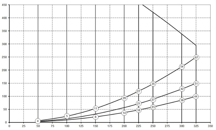
Resistance
of duct Note:
system The stated
[Pa] value in the
circle is the
capacity (in
Watt) per
fan.
Flow rate [m3/h]
Flair 325 615674-F Brink / 73.2 Connections and dimensions
The Flair appliance is available in a left-hand and right-hand version. With a left-hand version the “warm”
connections (from dwelling 3 and to dwelling 1) are on the left-hand side of the appliance; the condensate
discharge is then mounted at the right-hand opening below the appliance. With a right-hand version the “warm”
connections (1 & 3) are on the right-hand side of the appliance.
Left-hand version
All dimensions in millimeters. Diameter of all collars is 160 mm
1 To dwelling
2 To outside
3 From dwelling
4 From outside
5 Electrical connections
6 Siphon connection
7 Exhaust air filter
8 Supply air filter
9 Mounting
Flair 325 615674-FRight-hand version
All dimensions in millimeters. Diameter of all collars is 160 mm
1 To dwelling
2 To outside
3 From dwelling
4 From outside
5 Electrical connections
6 Siphon connection
7 Exhaust air filter
8 Supply air filter
9 Mounting
Flair 325 615674-F Brink / 93.3 Exploded view of appliance
The appliance shown above is a left-hand version: in the case of a right-hand version, the connector of the preheater, bypass valve
and the siphon connector are installed in mirror image!
1 Touchscreen 12 Heat exchanger
2 USB connector (X13) 13 Motor bypass valve
3 Service connector 14 Exhaust air filter
4 LED indicator 15 Bypass valve
5 Maximum protection preheater 16 Power cable 230 volt
6 Preheater 17 Relay output (X19) )
7 Temperature sensor 18 24 volt connector (X18)
8 Supply filter 19 eBus connector (X17)
9 Exhaust fan 20 24 volt connector (X16)
10 Siphon connector 21 Modbus/ Brinkbus connector (X15)
11 Supply ventilator 22 Multiple switch connector (X14)
Flair 325 615674-F4 Operation
4.1 Description
The appliance is supplied ready for plugging in and works automatically according to the standard settings. The
discharged dirty indoor air warms up the fresh clean outdoor air. That saves energy while fresh air is supplied to
the desired rooms.
The control system has four ventilation modes. The air flow rate can be adjusted for each ventilation mode. The
constant volume control system ensures that the ventilation balance between the supply and exhaust fan is
realized independent of the duct pressure.
If no external control is connected on to the appliance, then the appropriate ventilation model can be chosen on
the touchscreen display.
For external control a 4-way switch (® Connecting extra multiple switch with filter indication page 40) can, for
example, be chosen, but control is also possible with the Brink Air Control (® Connecting Brink Air Control page
42), CO2 sensor(s) (® Connecting CO₂ sensor(s) page 44), a humidity sensor (® Connecting humidity sensor
page 43), 2-zone demand control (® Demand-driven ventilation 2.0 page 45) of the Brink App.
4.2 Bypass
The 100% bypass makes it possible to supply outside air, which is not heated up by the heat exchanger.
Particularly during summer nights it is desirable to supply cooler outside air. The warm air in the dwelling is then
replaced as much as possible by cooler outside air.
The bypass valve opens and closes automatically when a number of conditions are met (see table below for
bypass conditions).
Follow step numbers 2.1 to 2.6 in the settings menu in the user interface, (® Setting values standard appliance
page 52) in order to adjust the operation of the bypass valve.
Bypass valve preconditions
▪ The outdoor temperature is higher than 10°C (adjustable between 7°C and 15°C at step no. 2.3) and
Bypass ▪ the outdoor temperature is lower than the indoor temperature of the dwelling and
valve open ▪ the outdoor temperature is higher than 24°C (adjustable between 15°C and 35°C at step no. 2.2)
▪ The outdoor temperature is lower than 10°C (adjustable between 7°C and 15°C at step no. 2.3) C or
Bypass ▪ the outdoor temperature is higher than the indoor temperature of the dwelling or
valve closed ▪ the temperature from the dwelling is lower than the set temperature at step no. 2.2 in the settings
menu minus the set temperature at the hysteresis (step no. 2.4).
The appliance features a ‘Bypass boost’ function. This means that when this function is switched on (can be
switched at step 2.5) the ventilation mode with an opened bypass valve goes to maximum air flow rate (adjustable
at step no. 2.6).
Flair 325 615674-F Brink / 114.3 Frost protection
To prevent freezing of the heat exchanger at low outdoor temperatures, the appliance features a frost control.
Temperature sensors measure the temperatures in the appliance, when required a preheater is switched on. If in
the event of very low temperatures the preheater has insufficient capacity, stepless unbalance is created in the
appliance.
The software ‘recognizes’ the appliance.
4.4 Plus version
The ‘Plus’ version is equipped with an extra control board with more connections for various applications.
This extra control board is located in a plastic housing behind the existing control board on top of the appliance.
It is also possible to remove the entire Plus pcb including casing from the appliance and mount it on, for
example, a wall separate from the heat recovery appliance; this can be handy in certain circumstances such as a
poor WiFi signal from the Plus pcb.
A standard heat recovery appliance can also later be modified into a Plus version using the Plus pcb upgrade set.
1 = Flair 325 appliance with mounted Basic pcb
2 = Plus pcb mounting plate
3 = Plus pcb
4 = Plus pcb protective cap
Flair 325 615674-F5 Installation
5.1 Installation general
Installing the appliance:
1. Placing the appliance (® Placing the appliance page 13 )
2. Connecting the siphon and condensate discharge (® Connecting the condensate discharge page 14)
3. Connecting the air ducts (® Connecting air ducts page 15)
4. Electrical connections (® Electrical connections page 16)
The installation and installing should meet the following requirements:
▪ Quality requirements of ventilation systems in homes, ISSO 61.
▪ Quality requirements of balanced ventilation dwellings, ISSO 62
▪ Regulations regarding the ventilation of homes and residential.
▪ Safety provisions for low-voltage installations
▪ The regulations for connecting indoor plumbing in homes and residential buildings.
▪ Any additional regulations of the local power companies
▪ The installation regulations of the Flair 325 appliance.
▪ In addition to the above design and installation requirements and recommendations, the national building and
ventilation regulations must be respected.
5.2 Placing the appliance
The Flair 325 (Plus) appliance can be mounted onto the wall with the supplied mounting bracket. For a vibration-
free installation, the appliance must be mounted to a solid wall with a minimum mass of 170 kg/m2. A gypsum
block or metal stud wall does not suffice! Additional measures such as double panelling or extra studs are
required in that case. On request, a mounting support for floor mounting (with the same minimal mass) is
available.
In addition, the following aspects must be taken into account:
▪ The appliance must be installed in an insulated frost-free room, in order to, for example, prevent freezing of
the condensate discharge
▪ The appliance must be placed level.
▪ The appliance must not be placed in a room with a high level of condensation (such as a bathroom).
▪ In order to prevent condensation on the outside of the appliance, the installation room must be ventilated.
▪ The installation room must be able to provide a condensate discharge with a sufficient water seal and drop for
the condensed water.
▪ Newly built houses with a lot of moisture from the construction work need to be ventilated in a natural manner
before being put to use.
▪ Make sure there is a free space of at least 70 cm at the front of the appliance and a free headroom of 1.8 m.
▪ Make sure there is a free space of at least 25 cm above the appliance, for connecting the appliance and any
necessary servicing of the circuit board.
Flair 325 615674-F Brink / 135.3 Connecting the condensate discharge
The condensate discharge line for the Flair 325 appliance is located in the lower panel. The condensate is
discharged through the drainpipe. The siphon (with built-in aerator) is supplied separately with the appliance and
must be fitted by the installer below the appliance (bayonet connection). The siphon has an external connection
diameter of 32 mm. The siphon is connected to the inner sewer system. It is recommended to fit an odor trap
between the sewer system and siphon in order to avoid unpleasant odors.
Important
Never switch the two condensate discharge connections below the appliance!
It is recommended to use a 32 mm connection with gasket (HT DN32) (not supplied with the appliance) so that
the siphon can be cleaned easily in the future.
Important: During assembly always apply a lubricant, such as acid-free vaseline, to the rubber sealing ring in the
gasket. This gasket connection has to be disconnected when servicing the appliance! The siphon must
not be glued to the condensate discharge line.
The condensate discharge can be connected, for example, with a straight or angled connection with gasket. Slide
the condensate discharge connection with gasket with sufficient length across the connection of the siphon.
A = Flair 325 right-hand version
B = Fitting siphon below in Flair
appliance
C = Examples with condensate
discharge connections with
gasket HT DN32
D = Detachable connection
E = Example of odor trap
Flair 325 615674-F5.4 Connecting air ducts
All air ducts must be installed airtight. The collars on the Flair appliance are provided as standard with sealing
rings.
In order to prevent condensation on the outside of the outdoor air supply duct and the air exhaust duct from the
Flair appliance, these ducts have to be provided with an external vapor barrier as far as the appliance. If
thermally insulated piping is used here, additional insulation is not necessary.
For compliance with the maximum installation noise level of 30 dB(A), it will have to be assessed for every
installation what measures will be required to limit the noise. In order to optimally dampen the noise of the fans
from and to the dwelling through the duct, at least mufflers of no less than 1 m are required, but additional
measures may be necessary.
Prevent crosstalk through the air supply and discharge ducts by using separate branches to the diffusers. If
necessary, the supply ducts must be insulated, for instance when they are installed outside the insulated
envelope.
The outside air supply should be arranged from the shadowed side of the dwelling, preferably from the wall or an
overhang.
The discharge duct must be fed through the roof boarding in such a way that no condensation forms in the roof
boarding.
The discharge duct between the Flair appliance and the roof sleeve should be such that surface condensation is
prevented.
Always use an insulated ventilation roof sleeve.
In order to keep the noise levels down, it is recommended to restrict the external duct pressure to 100 Pa. If the
resistance of the duct system is higher than the maximum curve of the ventilator, the maximum ventilation
capacity will be lower.
The air speeds must be limited to a max. of 5 m/s in the main ducts and 3.5 m/s in the branches.
The location of the discharge of the mechanical ventilation air and the sewer stack vent must be chosen to
prevent noise nuisance.
The location of the input valves must be chosen in such a way to prevent fouling and drafts. We recommend using
Brink input valves.
When using flexible mufflers, account must be taken during the installation that these may need to be replaced
after a period of time.
Install sufficient overflow openings, door gap 2 cm.
Flair 325 615674-F Brink / 151 = Flair 325 right-hand version (place level)
2 = Preferred ventilation air supply
3 = Sewer release
4 = Preferred location of ventilation air discharge; Use Brink insulated ventilation roof sleeve
5 = Thermally insulated piping
6 = Condensate discharge
7 = Sound absorber(s)
8 = Duct to and from house
6 = Condensater discharge
7 = Sound absorber(s)
8 = Duct to and from house
5.5 Electrical connections
5.5.1 Connecting the power plug
The appliance can be connected to an easily accessible, earthed wall socket
with the plug that is mounted to the appliance. The electric installation must
comply with the requirements of your power company.
5.5.2 Connecting the multiple switch
The multiple switch (not supplied with the appliance) is connected to the modular connector type RJ12
(connector X14) that is placed on the rear of the display cap of the appliance (® Exploded view of appliance page
10). For connection examples of multiple switch (® Connecting position switch page 37). A wireless remote
control (® Connecting wireless remote control (without filter indication) page 39) and a combination of multiple
switches is also possible (® Connecting extra multiple switch with filter indication page 40).
The 4-way switch can also be used to activate a 30-minutes boost mode by putting the switch to setting 3 for less
than 2 seconds and directly turning it back to setting 1 or 2. The boost mode can be reset by putting the switch to
setting 3 for longerthan 2 seconds or by switching it to absence mode ( ).
Flair 325 615674-F5.5.3 Connecting the eBus connector
For connecting an eBus connector, the 2-pole detachable (green) connector X17 is located at the rear of the
display cap (® Exploded view of appliance page 10). The eBus protocol may for instance be used to connect the
Brink Air Control (® Connecting Brink Air Control page 42). Because of polarity sensitivity, always connect
contacts correctly; the appliance will not work if these contacts have been interchanged! The optional CO2
sensor(s) or an extra eBus preheater or postheater (® Electrical diagram page 35) can also be connected onto
the eBus connector.
5.5.4 24 volt connection
On the X16 & X18 connector of the basic pcb, 24 volt is available.
Connector X-16 is for 24 volt connection of the optional Plus pcb.
For position connection (black) connector X16 & X18 (® Electrical diagram page 35). Maximum current
reduction at plug X16 and X18 is 5 VA per connection.
5.5.5 Connecting humidity sensor
The optional humidity sensor has to be connected onto the the X07 connection of the basic pcb. For this, use the
cable supplied with the humidity sensor. In order to connect the humidity sensor, the plastic cover above the
control has to be taken off, after which the X07 connection is accessible.
For connecting the humidity sensor, see ® Connecting humidity sensor page 43.
5.5.6 BrinkBus Connection
The Modbus/ Brinkbus (red) connector X15 can for example be used for coupling appliances (® Coupling
appliances using BrinkBus page 18).
The function of this connector can be adjusted using step number 14.1 to 14.4 in the settings menu.
If the appliance is fitted with a Plus pcb, then this red connector X15 is also in use for connecting the Plus pcb;
several cables then have to be connected onto this connector X15.
5.5.7 Connecting "signal output” connector
The blue 2-pole screw connector X19. This connection is used to give a filter message or fault message.
If a filter or fault message is given in the appliance a contact is closed at connection X19. The operation of this is
set by following step number 16.1.
5.5.8 ModBus Connection
The appliance can be connected with a ModBus system such as a building management system.Using the (red)
3-pole connector X15 (or with the Plus version the red connector X06 on the UWA2-E pcb) a connection can be
made between the appliance and the ModBus system; (® Electrical diagram page 35) for the right connection.
For the correct setting of the jumpers X12, X121 & X122 see the explanation given with electrical diagram (®
Electrical diagram page 35); for more information and the correct modBus settings see the separate Modbus
manual on the Brink website!
Note: When ModBus is active, the ventilation mode cannot be changed using the display or, if applicable, the connected
multiple switch! Also any connected humidity sensor will not function.
Flair 325 615674-F Brink / 175.5.9 Coupling appliances using BrinkBus
Important
Because of polarity sensitivity, always connect the Brink Bus contacts X15-1 with one another,
and the contacts X15-2 and the contacts X15-3 with one another. Never connect X15-1, X15-2 or
X15-3 with one another!
Comment: If a Plus pcb has been installed; several cables would have to be connected onto the
X-15 connector.
Note: When the total length of the Brink Bus cables is longer than 10 m, then use a twisted-pair
cable for connection X15-2 & X15-3 (a twisted pair cable is also preferred with shorter lengths)!
For M (master): For S1 (Slave 1): For S2 (Slave 2):
Step no. 8.1 - Master Step no. 8.1 - Slave Step no. 8.1 - Slave
Step no. 14.1 - Brink Bus Step no. 14.1 - Brink Bus Step no. 14.1 - Brink Bus
A = Multiple switch
B = 3-pole connector red
C = Modular cable
D = 3-core low voltage cable
M = Master appliance (For example a Flair appliance type 4-0)
S1 / S2 = Slave appliances (For example a Flair appliance type 4-0); connect maximum of 10 appliances via Brink Bus
All Flair 325 appliances have the same air flow rate as the appliance that is set as "Master".
The fault messages of all appliances are shown on the display of the master appliance.
When using a Brink Air Control or the Brink Home, always connect this to the Master.
Flair 325 615674-F6 Display
6.1 General explanation of control panel
A display with touchscreen is located at the front of the appliance. This display is used to operate the appliance
and to provide the user with information about the status of the appliance. When the mains power is switched on,
the software version is first shown; the main screen is then displayed.
Main screen
1 = Current time
2 = Info connections (only displayed if applicable)
3 = Current date
4 = Set ventilation flow rate; the red bars indicate the selected ventilation flow rate.
In this example the active ventilation flow rate is 100 m3/h
5 = Active control
6 = Filter message (only displayed if applicable)*
7 = Fault (only displayed if applicable)*
8 = Access to settings menu
9 = Access to information menu
* Filter message and fault message are located in the same place on the display; fault display has a higher priority,
and so will always be shown first even when there is an active filter message!
The factory setting of the menu is English.
The desired language/ date & time can be modified in the settings menu ;for this, please refer to the settings value
table (® Setting values page 52) step number 15.1 to step number 15.10.
Flair 325 615674-F Brink / 196.2 Display layout
The screen is divided up into 6 zones where various symbols/displays can be shown per zone.
Layout of main screen
1 = Navigation screen
2 = Notification screen
3 = Screen with main function
4 = Connectivity information
5 = Time
6 = Date
The various symbols can be shown on the display. This depends on the screen that is shown, the version of the
appliance and any connected accessories.
Zone
Symbol on display Description
no.
1 By pressing here you get access to the information menu; here one can only read out values. It is
not possible to change these values.
By pressing here you get access to the settings menu. In this menu you can change the various
values. For all setting values of standard appliance (® Setting values standard appliance page 52).
The Plus version of the appliance has various setting values (® Setting values appliance with Plus
pcb page 55).
Caution: Incorrect settings can disrupt the operation of the appliance!
Use these arrows to go up or down the various menus or to increase or decrease the values of the
relevant settings.
This arrow takes you back one step in the menu.
This takes you back to the main screen.
2
Filter message symbol; this is only shown if the filter has to be cleaned or replaced. See chapter
"Filter cleaning" (® Cleaning filter page 29) for more information.
This symbol is only shown if a fault has occurred in the appliance; see chapter Faults (® Fault
analysis page 26) for more information.
Flair 325 615674-FZone
Symbol on display Description
no.
3
Control using multiple switch.
Control by means of Brink Home.
Control using touchscreen on appliance; this setting is active for half an hour.
Control using touchscreen on appliance; touchscreen is permanently set as multiple switch by
setting step number 15.8 to "yes".
Control using humidity sensor.
Control using CO2 sensor.
Control using demand-driven ventilation.
Break contact active or make contact active.
This appliance is set as Master appliance if a number of appliances are connected (cascade)
Appliance is set as Slave appliance; maximum of 9 appliances can be connected to a Master.
Control via eBus for example Brink Air Control .
Control via ModBus or BrinkBus.
Bypass boost is active.
Flair 325 615674-F Brink / 21Zone
Symbol on display Description
no.
4
Internet connection
Signal strength
USB connection active.
5 11:07 Current set time of the device.
6 02.01.2020 Current date.
Flair 325 615674-F6.3 Display information
When no keys are operated or when no deviating situation has developed (such as fault message or filter
message) then the light will go out two minutes after the last key has been operated.
When there is a filter message or a fault in the appliance, then the light of the display will be on permanently
until the fault has been solved or the filter message has been reset.
Pressing the Home button brings you back to the main screen from any particular menu; pressing the return
button takes you back 1 step in the menu.
Briefly press the display (shorter than 5 seconds) to switch on the display backlight without changing anything in
the menu; the display lights up for 2 minutes.
By pressing one of the quarter circles on the main screen, the ventilation mode can be quickly adjusted.
The ventilation mode that has be set in this way remains active for half an hour; this is visible on the display by a
hand with a clock.
The touchscreen can also be permanently set as multiple switch; to do this step number 15.6 in the settings menu
has to be set to “yes”.
Warning:
Incorrect settings can seriously disrupt the proper functioning of the appliance!
Flair 325 615674-F Brink / 237 Starting appliance
7.1 Switching appliance on and off
Switching on:
▪ Switching on the mains power:
1. Connect the 230 V power plug to the electric system.
2. During the startup of the appliance, the version of the software is displayed.
If the appliance has been without power for a long time (more than approx. 1
week), you will have to reset the correct language, time and date in setting
menu .
3. The appliance will then operate immediately after this according to the mode
of the multiple switch. If no multiple switch is connected then the appliance
operates always in mode 1.
Switching off:
▪ Switching off mains power:
1. Pull the 230 V power plug from the electric system; the appliance is now free
of voltage.
2. Nothing is now shown on the display.
Warning!
When working on the appliance, always first take the voltage from the appliance by
pulling the power plug.
7.2 Setting the air flow
Good ventilation contributes to healthy air in the home, optimal comfort and the proper functioning of the
installation.
The air flows of the appliance have been set in the factory as follows 50, 100, 150 and 250 m3/h. The performance
and the energy consumption of the appliance depend on the pressure drop in the duct system, as well as on the
filter resistance. If these conditions are not complied with, the air flow rate of the higher mode will automatically
be adjusted.
Changes can be carried out in the settings menu .
Go in the settings menu to steps 1.2 to 1.4 to adjust the air flow.
Please note!
The highest demanded ventilation mode has priority. If the external multiple switch is set to mode 3, then the
ventilation mode cannot be adjusted to a lower mode on the main screen.
An exception to this is ventilator mode 0. If mode 0 is chosen on the display: control from other switches,
sensors, etc. is not possible.
Flair 325 615674-FFor connected CO2 sensors the air flow will be steplessly controlled between mode 1 and 3 depending on the
measured PPM values: for a connected humidity sensor the air flow will be switched to mode 3 when this is
switched on.
7.3 Other settings for installer
In addition to the air flow, it is also possible to change other settings of the appliance; for an overview of these
settings of a standard appliance (® Setting values standard appliance page 52 ) and appliance with Plus pcb ( ®
Setting values appliance with Plus pcb page 55).
Changes can be carried out in the settings menu .
Warning:
As changes in the settings menu can disrupt the proper functioning of the appliance,
changes of settings not described here require consultation with Brink Climate Systems B.V.
Incorrect settings may seriously affect the proper performance of the appliance!
7.4 Factory settings
It is possible to simultaneously revert all the changed settings back to the factory settings.
All changed settings are then back to the values they had when they left the factory; all message and fault codes
are also deleted from the service menu.
The filter message, however, is not reset!
For returning to factory settings, open the settings menu .
Under appliance settings, the appliance can be returned to factory settings through step number 15.9.
Caution!:
With a Flair 325 Plus, after resetting to the factory setting, step number 14.1 must be reset to
BrinkBus in the settings menu!
Flair 325 615674-F Brink / 258 Fault
8.1 Fault analysis
When the appliance's control system detects a fault, this is indicated on the display by a spanner symbol, possibly
also with a fault number.
The appliance makes a distinction between a fault at which the appliance keeps running (limitedly) and a serious
(locking) fault for which both fans are switched off.
8.2 Display Codes
Non-locking fault
When the appliance detects a non-locking fault, it will keep running (limitedly). The (permanently lighted) display
shows the fault symbol. Press the fault symbol for an explanation/ solution to the fault.
The screen can be left by pressing the "Home" button.
If a fault cannot be solved, please contact the installer.
1. Requested supply flow rate is not reached
Locking fault
When the appliance detects a locking fault, it will no longer work. With a locking fault the settings and
information menu are also switched off.
The (permanently lighted) display shows the fault symbol (spanner) together with a fault code. The red LED on
the multiple switch (if applicable) will be blinking. The appliance remains in this fault mode until the problem in
question has been solved. Then the appliance will reset itself (Auto reset) and the display returns to the display of
the operating situation. Contact the installer to remedy this fault.
1. Supply fan defective
A locking fault cannot be remedied by taking the voltage from the appliance; first the fault has to be solved.
Flair 325 615674-FWarning!
When working on the appliance, always first take the voltage from the appliance by pulling the
power plug.
In the table below the locking faults are marked with an * after the fault number.
The display shows a brief explanation of this fault code.
If there is reference to the "Standby" mode of the appliance, then both fans are shut down but there is still
something shown on the display of the appliance.
Fault Sub Appliance
Cause User action
code code action
E190 E1000 Self-test not good No action
E152 * E1001 * Flash memory faulty Stop appliance if Replace basic pcb UWA2-B
possible
E153 E1002 EEPROM memory Appliance goes Replace basic pcb UWA2-B
defective to factory setting;
fan setting 2
E105 E1011 Requested supply flow None Clean or replace filters
rate is not achieved Check that ducts are not blocked
E104 E1012 Requested exhaust flow None Clean or replace filters
rate is not achieved Check that ducts are not blocked
E000 * E1013 * Temperature of outside Appliance goes Depending on the situation:
air too high to standby In the event of warm weather and a supply directly below the
tiles, wait until the air has cooled or install a roof sleeve instead
of duct under the tiles
In the event of cold weather or when there is no air from below
the tiles, take the voltage from the appliance and replace air
temperature sensor (NTC)
E105 * E1100 * Supply fan defective; Appliance goes Replace supply fan
general message to standby Fault is reset automatically when voltage is put back on
appliance.
E104 * E1120 * Exhaust fan defective; Appliance goes Replace exhaust fan
general fault message to standby Fault is reset automatically when voltage is put back on
appliance.
E103 E1200 Bypass defective; general None Check wiring
fault message Replace bypass or wiring harness
E106 * E1300 * Sensor NTC1 defective; Appliance goes Check wiring
general fault to standby Replace NTC sensor or replace wiring
E111 E1400 RHT sensor 1 defective; No humidity Check wiring
general message control Replace RHT sensor or replace wiring
E113 E1600 Internal preheater Frost protection Check fuses
defective; general fault goes to Check wiring; replace if damaged and replace otherwise the
message imbalance mode internal preheater
Fault is automatically reset when the voltage is put back on the
appliance.
E114 E1500 Multiple switch Appliance goes Replace multiple switch
defective; general fault to mode 1
E130 E1800 Relay output 1 defective; Signal output not Take voltage from appliance
general fault available Replace UWA2-B pcb
Fault is automatically reset when voltage is again put back on
appliance.
Flair 325 615674-F Brink / 27Fault Sub Appliance
Cause User action
code code action
E155 E2000 Touchscreen fault; Fault codes only Check wiring to touchscreen; replace wiring
general fault message visible when if damaged; replace touchscreen if fault still occurs replace
using service UWA2-B
tool Fault is automatically reset when voltage is again put back on
appliance
E120 E2100 EBus fault; general fault Brink Air Control Check wiring to accessories/ Brink Air Control
message and other Check accessories/Brink Air Control and replace if defective
accessories If there is still a fault after this: Take voltage from appliance and
connected to replace basic pcb UWA2-B
eBus do not
work. Appliance
is working
E121 E2200 BrinkBus general fault Brink Air Control Check wiring to accessories/ Brink Air Control
message and other Check accessories/ Brink Air Control and replace if defective
accessories do If there is still a fault after this: Take voltage from appliance and
not work. replace basic pcb UWA2-B
Appliance is
working
E122 E2300 Internal ModBus fault; Appliance goes Check wiring and connections to UWA2-B and the fans
general fault message to standby Replace cable harness if damaged; Then exchange UWA2B,
exhaust fan and supply fan
E123 E2400 External ModBus fault; Operation via Check cabling of accessories; replace if damaged
general fault message Modbus does not Check accessories; replace if defective
work If fault still occurs: Take voltage from appliance and replace
UWA2-B basic pcb
E124 E2500 USB port general fault USB interface not Replace USB accessory
message usable If the fault is not remedied after this: take the voltage from the
appliance and replace UWA2-B basic pcb
E170 E2600 One or more CO2 Appliance is Check cabling and CO2 sensor(s); replace if damaged
sensor(en) defective; working; no CO2 Check CO2 sensor(s); replace if defective
general fault message regulation
E171 E2700 External preheater or No preheater / Uncouple preheater and check preheater fuse; replace fuse if
fuse defective; general comfort control defective
fault message responds Has the fault not yet been remedied:
differently Replace external preheater
Put voltage back on appliance
Fault has automatically been reset
E172 E2800 External postheater or No postheater / Uncouple postheater and check postheater fuse; replace fuse if
fuse defective; general comfort control defective
fault message responds Has the fault not yet been remedied:
differently Replace external postheater
Put voltage back on appliance
Fault has automatically been reset
Flair 325 615674-F9 Maintenance
9.1 Cleaning filter
The maintenance for the user is limited to the periodic cleaning or replacement of the filters.
The filter only has to be cleaned if this is indicated on the display (the filter symbol is shown here) or, if a
multiple switch with filter indication has been installed and the red LED of the switch is on.
The filters should be replaced each year.
After the filter has been cleaned 3 times, it must be replaced by the 4th time.
The appliance must never be used without filters.
Cleaning and replacing the filters:
Press the filter symbol for longer than 3 seconds to open the filter wizard.
Now follow the instructions that appear on the display to clean and/or replace the filter.
This filter wizard cannot be interrupted.
When all the instructions on the menu have been followed and confirmed, then the filter wizard is closed by
pressing the “Home” button and the display then returns to the main screen; the filter message is reset and
the filter message now disappears.
Comment:
If the filter wizard is opened in order to replace the filter whilst there is no filter message on the display screen,
go in the settings menu to step number 4.2 to open the filter wizard. Now follow the instructions on the
display, and once finished the timer of the filter message is reset.
It is also possible to go in the settings menu using step number 4.3 to reset the filter directly without opening the
filter wizard; if “Yes” is chosen then in the settings menu this step number has to be left again by pressing
“Home” button or the " return" button .
The timer of the filter message is then reset!
Pressing the Home button brings you back to the main screen from any particular menu; pressing the return
button takes you back 1 step in the menu.
Flair 325 615674-F Brink / 299.2 Maintenance siphon
Cleaning the siphon
Every year the siphon must be disconnected and cleaned.
Flair 325 615674-F9.3 Maintenance installer
Installer maintenance includes cleaning the heat exchanger, internal preheater and fans. Dependent on the
conditions, this must done about once every three years.
1 Remove the power supply by pulling out the plug.
Open the filter door.
2 Remove the two filters.
3 Remove the front cover.
Flair 325 615674-F Brink / 314 Remove the heat exchanger. Be careful not to damage the foam parts in the appliance.
5 Wash the heat exchanger with hot water (max. 45°C) and a regular detergent. Then rinse the exchanger with
hot water.
6 Take EPS assembly, with which the fan is inserted into the appliance, out of the appliance.
Flair 325 615674-F7 Turn the fan a quarter of a revolution in the appliance.
8 Tilt the fan in such a way that this can be taken out of the EPS assembly; disconnect both fan cables from the
fan.
9 Now take the fan out of the appliance.
10 Repeat steps 6 to 9 for the other fan in the appliance.
Flair 325 615674-F Brink / 3311 Carefully clean both fans with a soft brush; do not use any water or cleaning agent.
12 Clean the internal preheater.
13 Place both fans back in the appliance and connect the disconnected fan cables once more; when doing so,
take care that the fan cables are “behind” the fans and that the fans are returned to their original position.
The left fan is indicated by "Left"; the right fans is indicted by "Right".
Comment: Do not change the position of the fans!!
14 Slide the cleaned heat exchanger carefully back into the appliance; when doing so, take care that the EPS parts
and rails in the appliance are not damaged, which could otherwise leads to internal leaks in the appliance.
Take care when returning the heat exchanger that the text on the type plate is not upside down!
Place the heat exchanger back such that this type plate is visible.
15 Put the front cover back on and screw it secure.
16 Install two new filters and close the front cover.
17 Reconnect the 230V power supply to the appliance.
18 Reset the timer of the filter message by setting the timer back to zero in the settings menu at step number
4.3.
19 After resetting the timer of the filter message the appliance returns to the main menu and the appliance is
once again ready for use.
Flair 325 615674-F10 Electrical diagram
Flair 325 615674-F Brink / 351 = Basic pcb Basic pcb
2 = Multiple switch (option) X15 = BrinkBus/ModBus
3 = Humidity sensor (option) X16 = 24V
4 = USB connector x17 = eBus
5 = USB stick for updating software (not supplied with appliance) X18 = 24V (max 5VA)
6 = Service connector X19 = Signal output
7 = Laptop with installed Brink service tool (not supplied)
8 = Touchscreen on appliance Plus pcb
9 = Valve motor bypass valve X03 = 24V
10 = Air temperature sensor X04 = BrinkBus
11 = Exhaust fan* X06 = ModBus
12 = Internal preheater incl. maximum security X08 = Contact input 1
13 = Supply fan* X09 = Contact input 2
14 = Power supply 230V 50Hz X10 = Relais output 1
15 = Brink Air Control (option) X11 = Relais output 2
16 = CO2 sensor eBus (option) X12 = Analoog input (0 to 10 V)
17 = Heater eBus (option) X13 = Analoog input (0 to 10 V)
18 = Zone valve demand-driven ventilation 2.0 (option) X14 = Analoog output (0 or 10 V)
19 = Plus pcb (option) X15 = Analoog output 2 (0 or 10 V)
20 = Connection on ModBus system (option) X16 = NTC 10K
21 = X12 is Jumper terminating resistance (120 W) ModBus (remove if X17 = LAN
terminating resistance has already been placed in ModBus system).
With Modbus application remove the jumpers X121 & X122; when
using BrinkBus place the jumpers X12, X121 & X122; remove
Jumper X07 from Plus pcb when a Plus pcb is applied.
Wire colours
* The control cables of the fans can be switched with no problem; C1 = brown
when the power is switched on the appliance determines itself C2 = blue
which is the supply and exhaust fan! C3 = green/yellow
When the appliance detects another fan (for example when a fan is C5 = white
replaced during service activities), then a “wizard” starts up C8 = grey
automatically; follow the instructions on the display for the correct C10 = yellow
connection of the fan cables. C11 = green
C17 = purple
Flair 325 615674-F11 Electrical connections
accessories
11.1 Connecting position switch
A multiple switch must be connected to the modular connector type X14. This modular connector X14 is
accessible from the rear of the control. With an appliance with Plus pcb the cover first has to be removed in order
to gain access to this modular connector (® Plus version page 12). Depending on the type of multiple switch that
is connected, one can use either an RJ11 or RJ12 plug.
It is best to use a 4-way switch with filter indication; always install an RJ12 connector in combination with a 6-
core modular cable.
When using a 3-way switch without filter indication always install an RJ11 connector in combination with a 4-
core modular cable.
Flair 325 615674-F Brink / 3711.1.1 Connecting position switch with filter indication
A = Flair appliance (For example a Flair appliance type 4-0)
B = 4-way switch with filter indication
C = Modular cable: Note: For the modular cable that is used, the “tab” of both modular connectors must be mounted facing
the mark on the modular cable. Wire colors C1 - C6 may vary dependent on the type of modular cable used.
Flair 325 615674-F11.1.2 Connecting wireless remote control (without filter indication)
A = Flair appliance (For example a Flair appliance type 4-0)
B = Receiver for wireless remote control
C = Transmitter with 4 settings (for example kitchen)
D = Transmitter with 2 settings (for example bathroom)
E = Any additional 2- or 4-settings transmitters (maximum of 6 transmitters can be signed on to 1 receiver)
F = Modular cable: Note: For the modular cable that is used, the “tab” of both modular connectors must be mounted facing
the mark on the modular cable. Wire colors C1 - C6 may vary dependent on the type of modular cable used.
Flair 325 615674-F Brink / 3911.1.3 Connecting extra multiple switch with filter indication
A = Flair appliance(For example a Flair appliance type 4-0)
B1 = Multiple switch with filter indication
B2 = Extra multi switch with filter indication
C = Splitter
D = Modular cable: Note: For the modular cable that is used, the “tab” of both modular connectors must be mounted facing
the mark on the modular cable. Wire colors C1 - C6 may vary dependent on the type of modular cable used.
Flair 325 615674-F11.1.4 Connecting extra multiple switch with filter indication
A = Flair appliance (For example a Flair appliance type 4-0)
B = Multiple switch with filter indication
C = Receiver for wireless remote control
D = Transmitter with 2 settings or 4 settings
E = Splitter
F = Modular cable: Note: For the modular cable that is used, the “tab” of both modular connectors must be mounted facing
the mark on the modular cable. Wire colors C1 - C6 may vary dependent on the type of modular cable used.
Flair 325 615674-F Brink / 4111.2 Connecting Brink Air Control
A = Flair appliance (For example a Flair appliance type 4-0)
B = Brink Air Control (option)
C = Two-core control cables
D = Green two-pole screw connector
E = Position green eBus connector to rear of control
Flair 325 615674-F11.3 Connecting humidity sensor
1 = Flair appliance (For example a Flair appliance type 4-0)
2 = Basis pcb
3 = Cover
4 = The cable that comes with RH cable
5 = RH (humidity) sensor
6 = Duct from dwelling
To switch on and set the sensitivity of the humidity sensor, go to step number 7.1 and 7.2 in the settings menu .
Flair 325 615674-F Brink / 4311.4 Connecting CO₂ sensor(s)
A = Flair appliance (For example a Flair appliance type 4-0)
B = 2-pole control cable for 24V power supply (black connectors)
C = 2-core control cable for eBus connection (green connectors)
D = CO2 sensor(s); connect a maximum of 4
E = Connection X17 (eBus) and X18 (24V) on Flair appliance
For switching the CO2 sensor(s) on and off, select the right setting at step number 6.1 in the settings menu ; in
order to set the minimum and maximum PPM value of the CO2 sensor(s) set, if necessary, the right values
following step numbers 6.2 to 6.9.
Flair 325 615674-F11.5 Demand-driven ventilation 2.0
Demand-driven ventilation allows the ventilation need to be matched to the air quality. Matching the ventilation
need with demand-driven ventilation can be done in two different ways, namely based on CO2 measurements or
based on a time program. Two different sets are available for this. Manual operation with the aid of an extra
connected multiple switch of course remains a possibility as well.
For further information regarding setting, operating and connecting demand-driven ventilation 2.0, refer to the
installation instructions supplied with the demand-driven device.
1 = Zone valve demand-driven ventilation
2 = Power 24 VDC
C1 =brown
3 = Brink Air Control
C2 = blue
4 = Valve motor zone valve C3 = green/yellow
5 = EBus connection X17 on Flair appliance( For example a Flair appliance type 4-0) C5 = white
6 = CO2-sensors (only applicable when demand-driven based on CO2) C10 = yellow
C11 = green
7 = Pcb demand-driven
8 = Dipswitch setting on pcb zone valve
Flair 325 615674-F Brink / 4511.6 Connecting postheater
1 = Heating coil
2 = Maximum savety with manual reset
C1 = brown
3 = 2-pole eBus connection X17 on Flair aplliance C2 = blue
4 = Temperatur sensor C3 = green/yellow
5 = PCB type UVP1 C4 = black
C5 = white
6 = Airflow direction
7 = Dipswitch setting Flair postheater
(For example a Flair appliance type 4-0)
Flair 325 615674-F11.7 Connecting preheater
1 = Heating coil
2 = Maximum savety with manual reset
C1 = brown
3 = 2-pole eBus connection X17 on Flair appliance C2 = blue
4 = Temperatur sensor C3 = green/yellow
5 = PCB type UVP1 C4 = black
6 = Airflow direction C5 = white
7 = Dipswitch setting Flair preheater
(For example a Flair appliance type 4-0)
Flair 325 615674-F Brink / 4711.8 Connecting Geo-heat exchanger
A geo heat exchanger can be connected to the
Flair appliance with Plus PCB.
Depending on the type of valve the geo heat
exchanger can be connected to different
connection of the Plus PCB:
X10 no. 1 & 2 - Relay output 1 (Factory setting)
X11 no. 1 & 2 - Relay output 2
X14 no. 1 & 2 - Analogue output 1 (0 - 10 V)
X15 no. 1 & 2 - Analogue output 2 (0 - 10 V)
Connect the outdoor temperature sensor to no. 1
and no. 2 of the 2-pole connectorX-16.
A = Min. temperature
B = Max. temperature
I = To dwelling
II = To outside
III = From dwelling
IV = From outside
When using a geo heat exchanger, parameter 11.1 must be changed from “OFF” to “ON”.
Step No. Description Factory setting Range
11.1 Switching on and off Off On/ off
11.2 Switch temperature 1 5°C 0.0 °C / 10.0 °C
11.3 Switch temperature 2 25°C 15.0°C / 40.0 °C
11.4 Mode valve 10 volt control Closed Open / Closed
Relay output 1/Relay output 2/
11.5 Valve control Relay output 1
Analogue output 1/Analogue output 2
Flair 325 615674-F12 Service
12.1 Exploded view
When ordering parts, in addition to the article code number (see exploded view), please state the heat recovery
appliance type, the serial number, the year of production and the name of the part:
N.B.: Appliance type, serial number and year of production are stated on the identification plate behind the plastic front
panel on the appliance.
Example
Appliance type Flair 325 Plus
Serial number 43000020021201
Year of production 2020
Part Filter
Article code 532759
Quantity 1
Flair 325 615674-F Brink / 4912.2 Service articles
Flair 325 615674-FNo. Article description Article code
1 Front panel complete 532763
2 Filters (2 items) ISO Coarse 60% 532716
3 Heat exchanger 532754
4 Fan (1 item) 532759
5 Bypass valve with motor complete 532760
6 Display pcb UBP-2 532752
7 Basic pcb UWA2-B 532750
8 Plus pcb UWA2-E (only applicable with Plus version) 532751
9 Mains plug and cable 230 V * 532756
10 Internal preheater incl. maximum security 532761
11 Temperature sensor NTC 10K 531775
12 Condensation discharge 532762
13 Cable set 532767
* The power cable is fitted with a circuit board connector. When replacing it, always order a replacement mains
cable from Brink.
To prevent dangerous situations, a damaged mains connection can only be replaced by a qualified
expert.
Flair 325 615674-F Brink / 5113 Setting values
13.1 Setting values standard appliance
The below setting values are for a Flair 325-appliance without Plus pcb.
Step
Description Factory settings Setting range Comment
No
1 Flow rate
1.1 Air flow rate setting 0 50 m³/h 0 or adjustable between 50 m³/h and 325
m³/h (never higher than step no. 1.2)
1.2 Air flow rate setting 1 100 m³/h Adjustable between 50 m³/h and 325
m³/h (not higher than step no. 1.3 or
lower than step no. 1.1)
1.3 Air flow rate setting 2 150 m³/h Adjustable between 50 m³/h and 325
m³/h (not higher than step no. 1.4 or
lower than step no. 1.2)
1.4 Air flow rate setting 3 250 m³/h Adjustable between 50 m³/h and 325
m³/h (not lower than step no. 1.3)
1.5 Imbalance permissible Yes Yes / No
1.6 Imbalance (Open fireplace) 0% 0% / +20%
1.7 Offset supply 0% -15% / +15% fan setting Value calculated
back to set flow
1.8 Offset exhaust 0% -15% / +15% fan setting rate, see screen
1:19 Default fan setting 1 0 or 1
2 Bypass
2.1 Mode Bypass Automatic - Automatic
- Bypass closed
- Bypass open
2.2 Bypass temperature "from
24 °C 15 °C / 35 °C
dwelling"
2.3 Bypass temperature “from
10°C 7 °C / 15 °C
outside”
2.4 Bypass hysteresis
2 °C 0 °C / 5 °C
2.5 Mode Bypass boost
Off On / Off
2.6 Fan setting selection Bypass
boost 3 0/3
3 Frost protection
3.1 Frost temperature 0 °C -1,5 °C /1,5 °C
3.2 Minimum intake temperature 10 °C 7 °C /22 °C
4 Filter message
Flair 325 615674-FStep
Description Factory settings Setting range Comment
No
4.1 Number of days until filter
message 90 1 / 365 days
4.2 Start of filter wizard No Yes / No
4.3 Filter reset No Yes / No
5 External heater
5.1 Preheater on and off Off On / Off
5.2 Postheater on and off Off On / Off
5.3 Temperature postheater 21 °C 15 °C / 30 °C
6 CO2 sensor
6.1 Switching eBus CO2 sensor off
Off On / Off
and on
6.2 Min. PPM eBus CO2 sensor 1 400 PPM 400 - 2000 PPM
6.3 Max. PPM eBus CO2 sensor 1 1200 PPM
6.4 Min. PPM eBus CO2 sensor 2 400 PPM
6.5 Max. PPM eBus CO2 sensor 2 1200 PPM
6.6 Min. PPM eBus CO2 sensor 3 400 PPM
6.7 Max. PPM eBus CO2 sensor 3 1200 PPM
6.8 Min. PPM eBus CO2 sensor 4 400 PPM
6.9 Max. PPM eBus CO2 sensor 4 1200 PPM
7 Humidity sensor
7.1 Switching humidity sensor on Off On / Off
and off
7.2 Sensitivity of humidity sensor 0 +2 = most sensitive
0 = basic setting
-2 = least sensitive
8 Cascade
8.1 Appliance setting 0 (Master) 0/9
(0=Master; 1 t/m 9 = Slave 1 t/m Slave 9)
12 Central heating + heat recovery
12.1 Status Off On / Off
14 Communication
14.1 Type of Bus connection ModBus Off / ModBus/ BrinkBus
14.2 Slave address 20 1 - 247 For Modbus
Flair 325 615674-F Brink / 53You can also read