Compact Low-Cost Filter for 5G Interference Reduction in UHF Broadcasting Band - MDPI
←
→
Page content transcription
If your browser does not render page correctly, please read the page content below
electronics
Article
Compact Low-Cost Filter for 5G Interference Reduction in UHF
Broadcasting Band
Oscar Fernández, Tomás Fernández                     and Álvaro Gómez *

                                          Engineering of Communications Department, University of Cantabria, 39005 Santander, Spain;
                                          fernanos@unican.es (O.F.); fernandt@unican.es (T.F.)
                                          * Correspondence: gomezal@unican.es

                                          Abstract: The allocation of part of the UHF band to 4G and 5G services has generated the appearance
                                          of channel interferences over the digital terrestrial television frequency band. In order to reduce these
                                          interferences, this work presents a novel and efficient band-stop filter implemented using microstrip
                                          technology. The filter, designed with rectangular split-ring resonators etched in the ground plane,
                                          provides a cutoff frequency above channel 48 (694 MHz), a high roll-off rate of 44 dB in 56 MHz and
                                          a rejection bandwidth of 250 MHz that covers the upper UHF band occupied by 4G and 5G with
                                          rejection levels close to 35 dB. The filter is manufactured entirely over a printed circuit board without
                                          lumped elements to reduce production costs, fine tuning after the assembly stage and maintenance.
                                          Moreover, it presents a compact subwavelength size of only 0.07 λ × 0.17 λ to facilitate installation,
                                          whether at the input of the TV terminal or integrated with the balun at the rooftop antenna.

                                          Keywords: 5G filter; digital dividend; digital terrestrial television; split-ring resonator


Citation: Fernández, O.; Fernández,
T.; Gómez, Á. Compact Low-Cost            1. Introduction
Filter for 5G Interference Reduction in        The analog television switch-off and its replacement by the digital terrestrial television
UHF Broadcasting Band. Electronics        (DTT) started a spectrum reassigning of the UHF band (470–862 MHz). The use of this
2021, 10, 974. https://doi.org/
                                          band by a more spectrum-efficient broadcasting technology, joined with good propagation
10.3390/electronics10080974
                                          conditions, motivated the release of the upper part of the UHF V band [1,2] and its allocation
                                          to 4G long-term evolution (LTE) and 5G cellular mobile systems.
Academic Editors: Christos J. Bouras
                                               From the point of view of DTT, the handicap of the coexistence of LTE and DTT
and Gyu Myoung Lee
                                          technologies in such close frequency bands is the apparition of interferences on the DTT
                                          signal and the overloading of DTT receivers [3–5].
Received: 15 March 2021
Accepted: 16 April 2021
                                               Different studies [6–14] analyzed the compatibility of DTT and LTE and the impact
Published: 19 April 2021
                                          of LTE interferences on DTT’s signal quality. They presented values of the ratio required
                                          between the DTT signal and the LTE interference to guarantee a certain quality level at
Publisher’s Note: MDPI stays neutral
                                          the DTT receptor (i.e., protection ratios). Three different DTT reception scenarios were
with regard to jurisdictional claims in
                                          considered: fixed outdoor, portable indoor and mobile. In these scenarios, the interference
published maps and institutional affil-   level depends on the distance between the LTE emitter and the DTT receiver, as well as
iations.                                  other factors such as the DTT technology [8,15–19], the DTT tuner technology [20,21], DTT
                                          receiver desensitization [22], the LTE traffic load [7,8,23] or even LTE channelization [7,8].
                                               Several works [11–14,24] proposed several approaches to minimize this problem. A
                                          straightforward solution is increasing the frequency distance between the LTE interfering
Copyright: © 2021 by the authors.
                                          signal and the desired DTT channel. Different analysis [20,21,25] showed that lower
Licensee MDPI, Basel, Switzerland.
                                          protection ratios were needed when interference and DTT signals were further away in
This article is an open access article
                                          frequency. However, UHF channel 48 and the lower part of the LTE uplink are only
distributed under the terms and           separated by a 9 MHz guard band (GB). Increasing this GB can be a solution, but with
conditions of the Creative Commons        important policy limitations and the counterpart of scarifying some part of the spectrum,
Attribution (CC BY) license (https://     which does not represent a spectrally efficient solution [8].
creativecommons.org/licenses/by/               We have to consider that the farther the interference emitter, the higher the signal-to-
4.0/).                                    interference ratio. Thus, guaranteeing a certain minimum physical distance between the

Electronics 2021, 10, 974. https://doi.org/10.3390/electronics10080974                                  https://www.mdpi.com/journal/electronics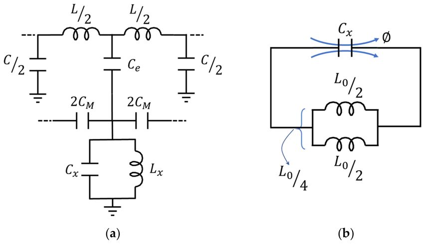
Electronics 2021, 10, 974                                                                                            2 of 14

                            LTE emitter and the DTT receiver should be a solution that would minimize interferences.
                            For example, the authors of [7,8] proposed, for indoor portable scenarios, separation
                            distances between 6 and 8 m to reach the required protection ratio (i.e., assure the received
                            signal quality). The handicap of this solution is that LTE user equipment (UE) is mainly
                            employed by moving users not aware of how near or far they are from the DTT receiver.
                                  A third option to solve this problem is filtering the LTE interferences. This filtering
                            can be done at the antenna, properly designed with a bandwidth limited to the DTT band-
                            width [24,26]. This is a good solution for new installations. However, for already deployed
                            installations, it can be expensive since it requires the antenna’s replacement. A better
                            option is LTE filtering at the DTT antenna output or even at the receiver input. This in-line
                            insertion of anti-LTE filters is the most simple and practical solution [6–8,11–14,24,27], since
                            it enables the reuse of existing infrastructure (e.g., the antenna and receiver). The authors
                            of [24] presented an overview of different existing filter technologies for individual or
                            communal antenna systems. In [3,4,7,28], different commercial anti-LTE filters manufac-
                            tured through traditional techniques were analyzed: discrete inductances and capacitances,
                            ceramic resonators and cavity filters.
                                  In this paper, we opted for a different design and manufacture method, taking into
                            account not only the technical aspects of its filtering response, but also other economic
                            and technical benefits related with the manufacturing, installation and maintenance. The
                            proposed filter is based on microstrip technology, a mature technology that facilitates the
                            design and manufacture of economic filters in a reliable way. The traditional techniques
                            for microstrip filter design (e.g., coupled lines, gaps, high-low impedance contrast) are not
                            valid in these frequency bands because of their large physical dimensions. Moreover, the
                            quality factor of the commercial substrates in these frequency bands is not high enough to
                            obtain the desired rejection levels with these topologies. Alternative filter design techniques
                            have gradually appeared, modifying the strip shape, nonuniform transmission lines [29,30]
                            or the ground plane, etching continuous [31] or periodic patterns [32] (electronic band
                            gaps (EBG)). In both cases, the resultant effect is the modification of the characteristic
                            impedance. However, one common handicap of these techniques is that they provide
                            electrically large structures.
                                  Metamaterials represent a good alternative to overcome this handicap. Although
                            they are usually periodic structures too, their compact design (tenths of wavelengths – λ)
                            provides smaller unit cells than EBG. The split-ring resonator (SRRs) and its complementary
                            version, the CSRR, are two of the most representative metamaterial structures [33]. The SRR
                            and CSRR, properly excited, provide negative permeability and permittivity, respectively.
                            This behavior, joined with its compact size (λ/20), makes SRR or CSRR suitable for the
                            design of filters when placed near the microstrip line [34,35].
                                  In this work, the authors present the design, characterization and experimental verifi-
                            cation of an anti-LTE filter based on microstrip technology combined with CSRRs. One of
                            the contributions of this paper is the analysis of some issues of the coupled CSRR microstrip
                            filters not previously analyzed, such as the use of multi-ring CSRR or the influence of
                            the CSRR shape on the filtering response. CSRRs are generally presented with circular or
                            square shapes, but to the authors’ best knowledge, the ratio between the ring side lengths
                            and the relative orientation of rectangular CSRRs with respect to the microstrip line are not
                            analyzed elsewhere.
                                  Another important contribution of this paper is its immediate applicability in 5G
                            interference filtering for commercial purposes. Thanks to the use of metamaterial particles,
                            this band-stop filter reduces the channel interferences coming from the upper UHF band
                            allocated to 4G and 5G (694–862 MHz) with a high roll-off rate and large rejection levels.
                                  Compared with existing anti-LTE filters [3,4,7,28], the proposed filter presents several
                            benefits. First, compared with LC filters, it avoids the microphony effect thanks to its
                            integrated design without lumped elements. In this way, it avoids variations of the electric
                            response of the filter due to mechanic vibrations requiring less maintenance. This lack
                            of lumped elements also avoids any additional adjustment to compensate deviations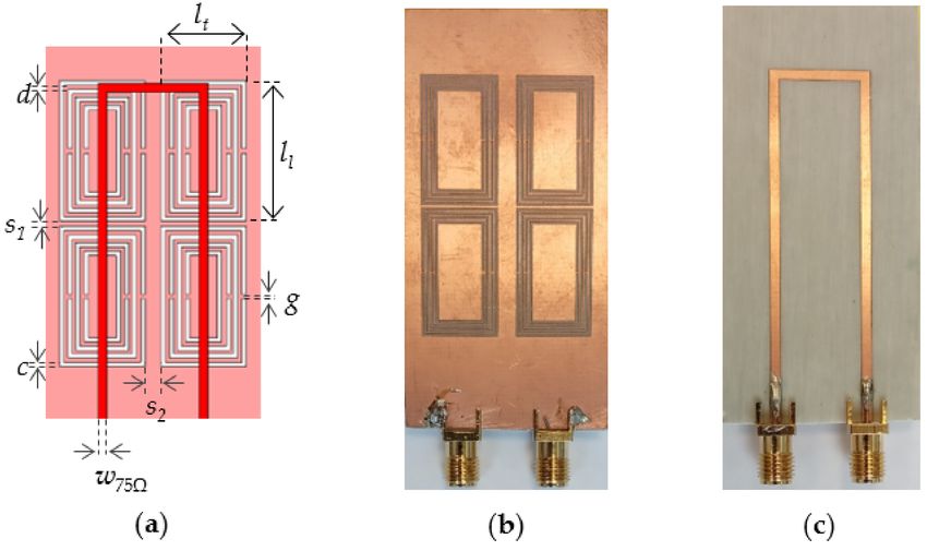
Electronics 2021, 10, 974                                                                                                   3 of 14

                            in the cutoff frequency or in the insertion losses, due to the tolerances of the lumped
                            components (i.e., the filter manufacturing is cheaper). Second, compared with cavity filters,
                            the compact filter size (due to the small dimensions of the CSRR) facilitates its installation
                            as an independent device connected to the input of the TV receptor or integrated in the
                            PCB joined to the antenna balun. In both cases, due to its design, it allows DC current
                            bypass to feed, if necessary, an active UHF antenna.

                            2. Microstrip Filter with CSRRs
                                  The proposed filter merges a microstrip transmission line with modified CSRRs to
                            develop compact band-stop filters in a simple and economical way. The operation principle
                            of the filter is based on the negative permittivity response of the CSRR [33]. When excited
                            with an axial electric field provided by the microstrip line, the CSRR behaves as an electric
                            dipole with a negative effective permittivity εr [36]. Near the resonance frequency, with
                            εr < 0, the propagation is inhibited, providing the required band-stop filter behavior. Here,
                            we propose the use of rectangular resonant split rings (Figure 1a), as this geometry allows
                            us to group in a smaller surface a higher number of CSRRs than the circular one and in a
                            more suitable position than the square one. In each CSRR, the rings are defined by the side
                            lengths ll and lt of the outer ring, the gap g, the ring width c and the separation between
                            rings d. In the filter (Figure 1b), the microstrip line width is w75Ω and the separation
                            between consecutive CSRRs is s1 . Rogers RO4003C has been chosen as the substrate, with
                            its main electrical parameters being εr = 3.55 and tan δ = 0.0027 with a 1.524 mm high and
                            35 µm thick copper cladding. Table 1 presents the values of the geometrical parameters of
                            the filter shown in Figure 1a, used to perform the different simulations and to construct
                            the final prototype. The simulations were carried out with the commercial electromagnetic
                            software Dassault Systèmes CST Studio Suite [37] using the frequency domain solver (finite
                            element method).

                            Figure 1. Schematic of the (a) two-ring CSRR and its geometrical parameters and (b) the preliminary
                            version of the filter with two CSRR elements etched on the ground plane (the substrate is removed
                            for better visualization).
                            Table 1. Numerical values of the geometrical parameters of the filter displayed in Figure 1a.

                                   Parameter               Value (mm)                Parameter               Value (mm)
                                       ll                      21.30                      c                      0.40
                                       lt                      11.30                     s1                      0.50
                                       g                       0.30                      s2                      3.00
                                       d                       0.30                     w75Ω                     1.63

                                In this section, we analyze the preliminary version of the filter presented in Figure 1b.
                            The equivalent circuit model of a CSRR-coupled microstrip filter was presented and vali-
                            dated in [38,39]. Each section of the filter can be modeled as a lumped-element circuit (see
                            Figure 2a), where the microstrip line is modeled through L, C and the CSRR by means of Lx
                            and Cx . Moreover, the electric field coming from the microstrip line that excites the CSRR is
                            modeled through the capacitance Ce (i.e., coupling between the line and resonator). Mean-
                            while, the coupling between the adjacent CSRRs is modeled through CM . In this paper, the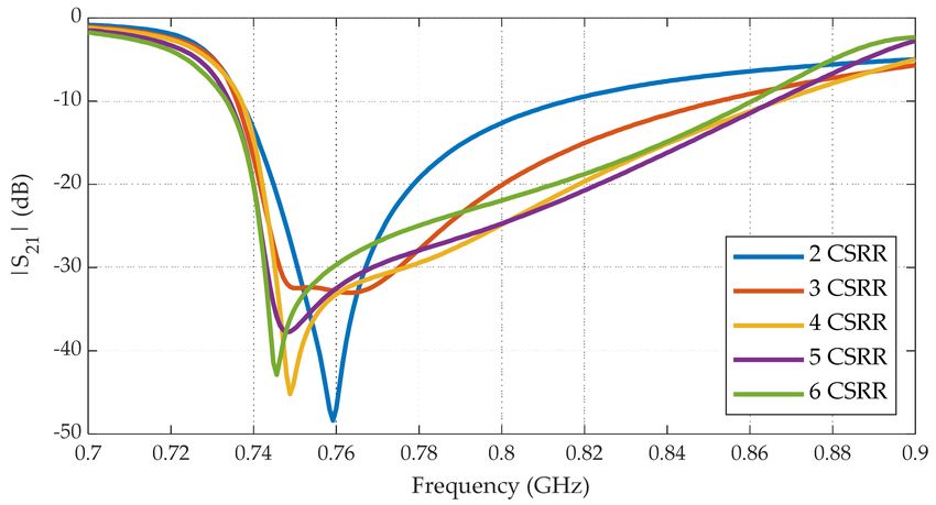
Electronics 2021, 10, 974                                                                                             4 of 14

                            circuit model is used as a qualitative tool to identify and understand key aspects of the
                            circuit model. In fact, the model does not take into account the dielectric or ohmic losses.
                            We have identified three key issues that will be analyzed in the following subsections: the
                            CSRR design, the coupling between the line and CSRR and the coupling between CSRRs.

                            Figure 2. (a) Equivalent circuit model of one section of the CSRR-coupled microstrip filter [38].
                            (b) Equivalent circuit model of a two-ring CSRR [33].

                            2.1. CSRR Design
                                 The authors of [33] presented the equivalent circuit model of a two-ring CSRR as the
                            combination of an inductor Lx with a capacitance Cx (Figure 2b). The resonant frequency
                            of the CSRR f 0 is obtained through Equation (1). The current distribution in the ground
                            plane in the quasi-static limit at f 0 is presented in Figure 3. At this frequency, in each half
                            of the CSRR—divided following the symmetry axis drawn in Figure 3—the current flows
                            through the metallic strip, as indicated by the red arrows, from one gap to the other:

                                                                              1
                                                                    f0 =     √                                           (1)
                                                                           2π L x Cx

                            Figure 3. Surface current distribution on the ground plane around a two-ring CSRR.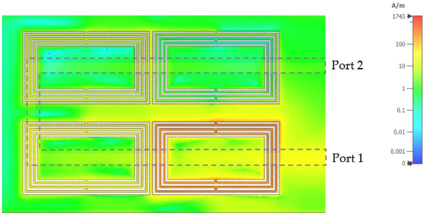
Electronics 2021, 10, 974                                                                                                       5 of 14

                                         The values of these L and C elements depend on the CSRR dimensions. The slot
                                   width c governs the distributed capacity, while the separation between slots d controls the
                                   distributed inductance. In both cases, the total capacitance and inductance depend on the
                                   ring size (i.e., ll and lt ). Thus, the reduction of the resonance frequency can be achieved
                                   by means of its geometrical parameters, mainly by placing rings closer within the limits
                                   of the etching machine or making them larger. The handicap of this last method is clear;
                                   a lower resonance frequency requires a larger CSRR. In this paper, we follow a different
                                   and novel method to reduce the resonance frequency without increasing the CSRR size
                                   by means of increasing the total inductance Lx . Bilotti et al. [40] showed that inserting
                                   more rings in an SRR increased the total capacity. In our CSRR case, we propose etching a
                                   larger number of rings (Figure 4a) to increase Lx . Following the Babinet principle [41], the
                                   total inductance and capacitance can be obtained from those presented in [40]. For a better
                                   understanding of the influence of the inductances in this multi-ring CSRR, we present in
                                   detail the modeling of the individual inductances and its equivalent circuit model.

                                   Figure 4. (a) Multiple CSRR with N = 4 rings. The blue arrows reflect the current directions at the
                                   transmission zero frequency. (b) Equivalent circuit model of the multi-ring CSRR.

                                         In Figure 2b, the inductances L0 /2 model the two metallic strips formed between
                                   the ring slots that join both “gaps”. These inductances are in parallel, and thus the total
                                   inductance Lx = L0 /4. In a similar way, in the multi-ring CSRR (Figure 4a), the inductance
                                   of a pair of consecutive rings, such as rings 1 and 2, is modeled by two inductances in
                                   parallel L12 /2. In turn, this pair of inductances is in series with the one formed by the next
                                   pair of rings (2 and 3), named L23 /2 and so on successively. Thus, the total inductance in
                                   the equivalent circuit model of a multi-ring CSRR, presented in Figure 4b, is formed by the
                                   series combination of the inductances of each pair of consecutive rings. Equations (2) and
                                   (3) represent the inductances of the first pair of rings (1 and 2) and between the rings n–1
                                   and n, wherein Lpul represents the inductance per unit length a coplanar strip line [33].

                                                                    L12 /2 = (ll − d + lt − d) L pul                               (2)

                                                           L(n−1)n /2 = L12 − 2[(n − 1)d + (n − 1)c] L pul                         (3)
                                      The total inductance (Equation (4)) shows that a CSRR with a higher number of rings
                                 presents stronger inductive coupling. However, although the total inductance depends on
                                 the number of rings N, as the rings get smaller (i.e., larger N), their inductances are lower
                                 and contribute in a smaller proportion to the total inductance Lx :
                           N                                                  N
                     L x = ∑ L12 − 2[(n − 1)d + (n − 1)c] L pul = N × L12 − 2 ∑ [(n − 1)d + (n − 1)c] L pul                 (4)
                            n =1                                                    n =1

                                        Figure 5 shows the 3 dB cutoff frequency fc of the filter, with CSRRs composed by a
                                   number of rings ranging from 2 to 8 and two geometries, square rings and rectangular
                                   rings. From these results, we could observe a downward frequency shift of about 180 MHz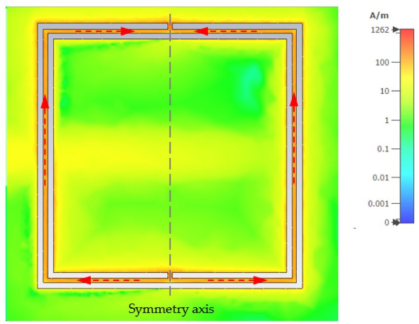
Electronics 2021, 10, 974                                                                                                  6 of 14

                            in the filter response when increasing the number of rings from 2 to 6. This effect was
                            equivalent to a 45% reduction of the area required by a two-rectangular ring CSRR with
                            a ratio between ring sides r = ll /lt = 1.9. It is worth mentioning that with more than six
                            rings, the response did not present significant changes. In these situations, the inner rings
                            were much smaller than the outer ones and presented a low inductance that contributed
                            very little to the total inductance Lx . Thus, for a given cutoff frequency, a number of rings
                            between 4 and 6 is recommended to obtain smaller CSRRs. With this consideration, we
                            selected CSRRs with four rings because the size reduction obtained with the six-ring CSRR
                            of less than 10% was not significant enough in comparison with the possible additional
                            tolerance errors that could be introduced when etching two additional rings.

                            Figure 5. Cutoff frequency as a function of the number of rings in the CSRR. The blue line represents
                            the square rings (r = 1), and the red line represents the rectangular rings (r = 1.9).

                                 Due to this miniaturization of the CSRR, we could combine a higher number of
                            elements or decrease the area required to implement the circuit. In fact, the number of
                            CSRR elements that the filter includes has a great influence over its frequency response
                            and its filtering capabilities. We can observe in Figure 6 that the increase of the element
                            number did not modify the filter frequency cutoff frequency fc but enlarged the band-stop
                            bandwidth (i.e., increasing the number of stages provided higher rejection levels). The use
                            of four elements was a good trade-off between a convenient filter response and its size.

                            Figure 6. Filter response with a different number of elements (CSRR) with ratio r = 0.5. Low coupling
                            between CSRRs is considered with separation s1 = 10 mm.

                            2.2. Coupling between the Microstrip Line and CSRR
                                 When the reactance of the branch formed by Ce in series with the Lx Cx circuit
                            (Figure 2a) is zero, the transmission of the signal is derived to the ground so there is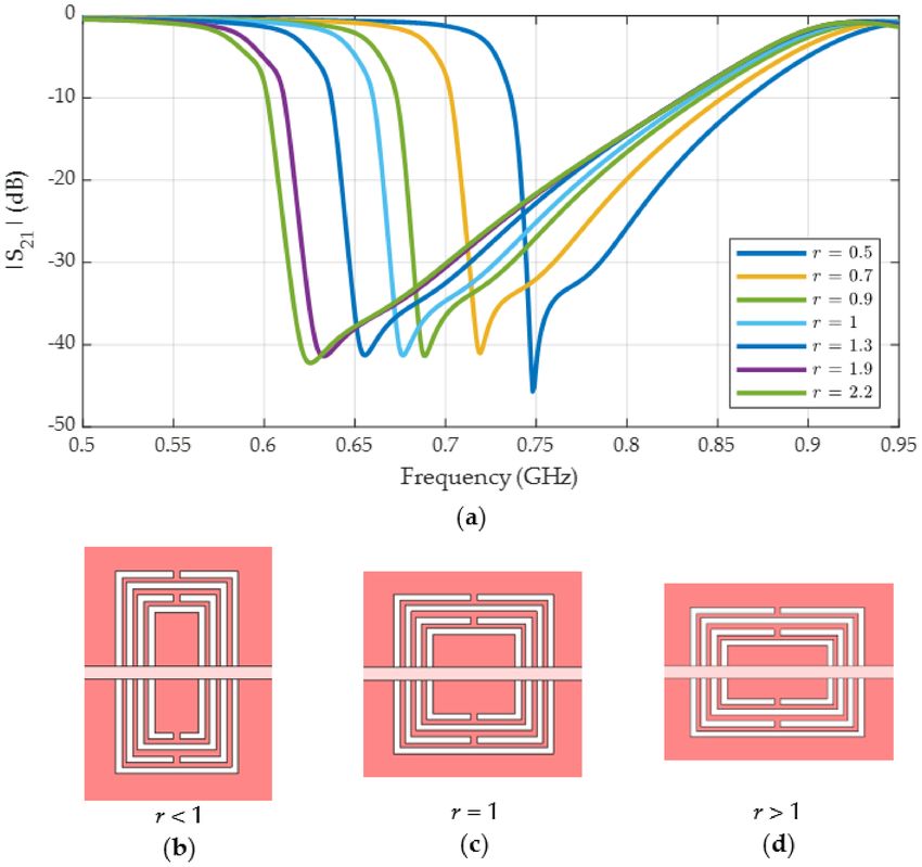
Electronics 2021, 10, 974                                                                                              7 of 14

                            no propagation of the signal to the output, thus providing a transmission zero. It is easy to
                            find that the transmission zero occurs at the frequency fz , as described in [38]:

                                                                                   1
                                                                fz =        p                                             (5)
                                                                       2π       L x (Cx + Ce )

                                  On inspecting Equation (5), it is clear that this frequency does not only depend on the
                            CSRR itself but also on the coupling between the line and the resonator, modeled by the
                            capacity Ce in the equivalent circuit model of Figure 2a. This coupling can be modified by
                            either changing the distance between the line and the CSRR (i.e., the substrate width) or
                            changing the material between both metalizations [42].
                                  In this paper, we propose a novel method that consists of the use of tailored rectangular
                            rings to modify the line–CSRR coupling. In CSRR-based microstrip filters, the rings are
                            etched in the ground plane and centered under the microstrip line, where the electric field
                            is confined [33]. In contrast to circular or square rings, we propose the use of rectangular
                            rings tailored and shaped to be placed just in the areas with higher electric field values. To
                            evaluate the advantage of using rectangular rings, we analyze the influence of the ratio
                            between their ring sides r = ll /lt on the filter response but maintain a constant perimeter
                            length of the rings (i.e., 2(ll + lt ) = constant).
                                  Figure 7a presents the module of the S21 parameter for different side ratios. It is
                            important to note that the ratio value modified the orientation of the CSRR with regard to
                            the microstrip line, as shown in Figure 7b–d. When the ratio was lower that one, the CSRR
                            rings were placed with the shorter side parallel to the transmission line. This geometry
                            enclosed a small surface underneath the line but also an area far from the line. Thus, very
                            different electric field levels were present along the surface enclosed by the rings. However,
                            for r > 1 (i.e., rectangular rings placed with the longer side parallel to the transmission line),
                            the area of the CSRR was mainly located in the area underneath the microstrip line, where
                            the highest values of the electric field were present. With this ring shape modification, a
                            higher coupling between the microstrip line and the CSRR was expected (i.e., an increment
                            of Ce ), and thus, following Equation (2), a lower fz . This fact can be checked in Figure 7
                            where, at a first glance, we can observe that when increasing the ratio, the transmission
                            zero frequency shifted downward. Moreover, on inspecting Figure 7 in detail, we can
                            observe that this variation was not linear with r; in fact, as we can see in Figure 8, the cutoff
                            frequency presented an exponential decay. As an example, modifying the ratio r from 1 to
                            0.5 increased the value of fc by about 80 MHz, while a variation of r from 1 to 1.9 resulted
                            in a decrease of 50 MHz.
                                  From a practical point of view, the proposed geometric arrangement and its relative
                            orientation can be also seen as a way of miniaturizing the filter size. For example, the effect
                            of changing r from 1 to 1.9 was equivalent to reducing the perimeter of the square CSRR by
                            about 8%. Here, it is worth to mention that increasing r also enlarged the filter size, so it is
                            important to select a trade-off between the stopband width and the filter size.
                                  On the basis of these results, the selection of the most suitable ratio value is key for
                            defining the stopband bandwidth, the cutoff frequency and the physical size of the filter.
                            Ratios between 1.5 and 2 are recommended to obtain a wide stopband bandwidth and a
                            low cutoff frequency.

                            2.3. Coupling between the CSRRs
                                 A third issue that has to be considered in the CSRR microstrip filter design is the
                            coupling between the resonators. The results of previous sections were obtained with the
                            resonators distanced far enough (10 mm) to produce a negligible coupling between them.
                            However, from a geometric viewpoint, a large separation also requires a large filter size,
                            something incompatible with the objective of a compact design. In this subsection, we
                            analyze the influence of the inter-resonator coupling on the filtering response by modifying
                            the distance between CSRRs. Moreover, we also evaluate the dependence of this coupling
                            on the length of the CSRR side facing the neighboring CSRR. Thus, the influence of the
Electronics 2021, 10, 974 8 of 14
aspect ratio of the CSRR is also analyzed, considering three different ratios: 0.5, 1 and 1.9.
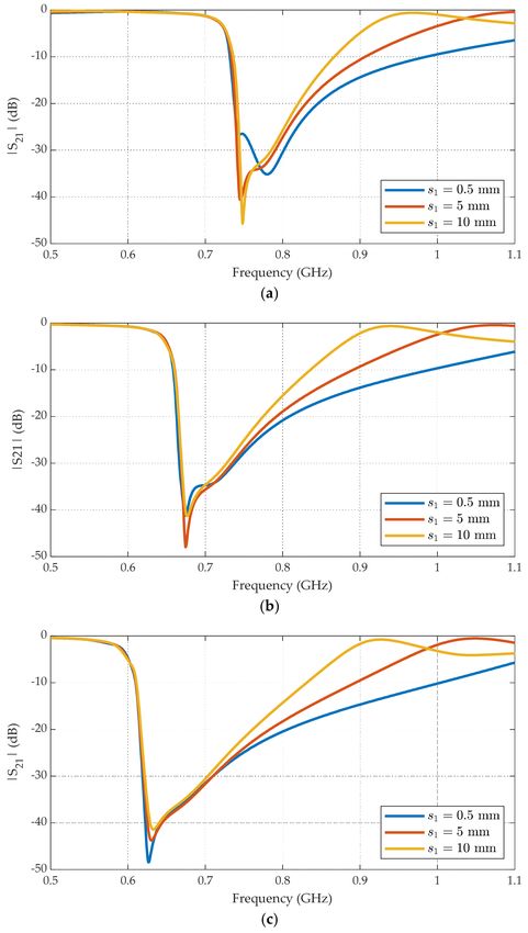
Figure 9 shows the module of the S21 parameter for three different coupling levels: high
coupling with s1 = 0.5 mm, moderate coupling with s1 = 5 mm and negligible coupling
with s1 = 10 mm for three different ratios: r = 0.5 (a), 1 (b) and 1.9 (c). We observed that
the main impact of the inter-resonator coupling was reflected in the stopband bandwidth.
As the CSRRs were closer, the cutoff frequency kept constant, but the other end of the
stopband shifted to higher frequencies, making the stopband wider. From an inter-CSRR
coupling point of view, we observed that the ring ratio only affected small ratios (r < 1) and
small distances (s1 ≤ 1 mm). In the example in Figure 9a, with r = 0.5, the stopband for
s1 = 0.5 mm was modified with respect to the other CSRR separations.
Based on these results, separation between CSRRs is a good way of controlling not only
the total filter size but also the stopband bandwidth without degrading other parameters,
such as the cutoff frequency or insertion losses. Special care should be taken into account
when using the combination r < 1 and s1 ≤ 1 mm.
Figure 7. (a) Module of S21 as a function of the ratio between ring sides (r) where the separation
s1 = 10 mm and N = 4. Below that is graphical representation of the orientation of the CSRR with
regard to the microstrip line for (b) r < 1, (c) r = 1 and (d) r > 1.
Figure 8. Cutoff frequency as a function of the ratio between the ring sides (r), where the separation
s1 = 10 mm and N = 4.Electronics 2021, 10, 974 9 of 14
Figure 9. Module of S21 (dB) of the filter with four CSRRs formed by four rectangular rings with
different ratios: (a) r = 0.5, (b) 1 and (c) 1.9. For each ratio, three different coupling levels were
considered: high coupling (s1 = 0.5 mm), moderate coupling (s1 = 5 mm) and negligible coupling
(s1 = 10 mm).
3. Compact CSRR Anti-LTE Filter
The proposed filter was designed to remove the unwanted signals generated by 5G
technology that use the 694–862 MHz UHF band since the implantation of the first and
second digital dividends. Taking this into account, the filter design objectives were the
following: a 3 dB cutoff frequency of the filter at the end of channel 48 (this is 694 MHz), a
sharp cutoff response (high roll-off rate) and a rejection band above 694 MHz of at least
168 MHz, with rejection levels of about 30 dB. In addition, the filter should be physically
small to facilitate its installation on the DTT antenna, rooftop or portable, or at the input of
the DTT receiver.
Based on these prerequisites and on the analysis presented in the previous section,
we designed a filter with four CSRRs, each formed by four rectangular rings with a ratioElectronics 2021, 10, 974 10 of 14
r = 1.84. This proportion between the side lengths placed the rings with the long sides
parallel to the strip line. To reduce the length of the filter, we modified the layout of the
transmission line, transforming the straight microstrip line into a U-shaped line as pre-
sented in Figure 10a. The values of all the geometrical parameters are presented in Table 1.
For the experimental characterization, we manufactured several samples (Figure 10b–c) by
a laser etching technique with an LPKF Protolaser S, with an etching resolution of 2 µm.
All the measurements were carried out using an Agilent N3383A PNA Series network
analyzer from 400 MHz to 1100 MHz with 3201 points.
Figure 10. (a) Proposed filter (top view), not to scale, with the substrate layer hidden to facilitate the
view and the manufactured filter’s (b) bottom view and (c) top view.
Figure 11 shows the module of the S11 and S21 parameters, normalized to 75 Ω, compar-
ing the results obtained from the simulations and measurements of the filter. Here, we can
see a good agreement between both results with the specified cutoff frequency at 694 MHz
and a rejection band of about 250 MHz. It is important to notice that only one transmission
zero was needed to obtain the required stopband to filter the UHF frequency band allocated
to 4G and 5G (694–862 MHz). Furthermore, it presented a deep stopband level, with a
maximum attenuation of 45 dB in the simulations and 35 dB in the measurements. In
the passband, the filter introduced very low attenuation, with insertion losses lower than
0.5 dB. Above the cutoff frequency, the module of the S21 parameter fell off rapidly, with a
roll-off rate of 44dB in 50 MHz. The discrepancies observed in the values of |S11 | in the
passband and |S21 | in the stopband may have been due to possible inaccuracies in the
substrate characterization at these frequencies.
Figure 11. Module of the S11 and S21 parameters of the proposed filter, with a comparison between
the simulations (solid) and the measurements (dots).Electronics 2021, 10, 974 11 of 14
Moreover, the filter size was only 35 × 65 mm, 0.07 λ × 0.17 λ, with λ being the
wavelength at 600 MHz, a compact subwavelength layout for a band-stop filter with such
a frequency response. This size facilitated its installation at the input of the TV receiver or
its integration at the antenna sharing the PCB with the balun.
Figure 12 represents the magnitude of the surface current distributions on the ground
plane at the transmission zero frequency. Although this filter presents a reciprocal behavior,
in this simulation, the transmitter was connected at Port 1 (i.e., this port would be connected
to the antenna), and Port 2 was connected to the receiver (i.e., it would be connected to the
DTT receiver). The first CSRR—the one next to Port 1—received the unfiltered signal and
thus presented the highest current amplitude levels. As the signal propagated through the
stages of the filter, it was attenuated. Therefore, as can be seen in the figure, the current
levels in the CSRR were rapidly decreasing, reaching values near zero at the fourth CSRR.
Figure 12. Current distribution in the microstrip filter ground plane at the transmission zero fre-
quency. The dashed line represents the microstrip line.
4. Conclusions
In this paper, we have presented an anti-LTE filter based on microstrip technology
that integrates particles with negative permittivity (CSRR). The novelty of the filter lies
in its previously unreported design, with a U-shaped transmission line and rectangular
CSRRs etched underneath the microstrip line in the ground plane. The importance of
the relative alignment of the rectangular CSRR with respect to the microstrip line and its
side length ratio for obtaining an efficient coupling has been demonstrated. In addition
to the filter size reduction, the arrangement of the resonators in a rectangular lattice also
enhanced the coupling among CSRRs from orthogonal directions, in contrast with the
in-line distribution. This design provides a high roll-off rate and a high rejection level in a
small device (only 35 × 65 mm) to facilitate its installation, whether at the input of the TV
terminal or integrated with the balun at the rooftop antenna. The filter is manufactured
entirely on a PCB without lumped elements to reduce the cost of manufacturing, fine-tuning
and maintenance.
The validity of the proposed design was demonstrated by comparisons between the
simulated and measured results, which showed good agreement. In the passband, the
insertion losses were lower than 0.5 dB, while in the rejection band, the attenuation reached
up to 45 dB. Moreover, it showed a very good roll-off rate in the transition between both
bands, where fc = 694 MHz. Although the filter was designed for ITU Region 1, it can be
easily modified for other ITU regions.
As a result, a fully functional small-size filter has been obtained. Compared with
other filter structures (e.g., lumped elements and resonant cavities) this filter provides low
fabrication and tuning costs, along with response reliability due to the lack of lumped
elements (i.e., component tolerance problems). Moreover, the proposed filter can beElectronics 2021, 10, 974 12 of 14
used either in indoor or outdoor systems without any modifications due to its band-
reject response, which is its capability to allow DC bias current passthrough to the roof
components. Finally, this work shows a general way to miniaturize microstrip-based filter
structures, achieved using coupled resonator clusters in the ground plane along with a
U-shaped transmission line in the signal plane.
Author Contributions: Conceptualization, T.F.; methodology, O.F., T.F. and Á.G.; investigation, O.F.,
T.F. and Á.G.; writing—original draft preparation, O.F.; writing—review and editing, O.F., T.F. and
Á.G. All authors have read and agreed to the published version of the manuscript.
Funding: This research was funded in part by the Ministerio de Ciencia, Innovación y Universidades
and in part by the European Regional Development Fund under Grant PGC2018-098350-B-C22.
Acknowledgments: The authors would like to also express their gratitude to all the staff of DICOM’s
assembling laboratory staff, as well as Eva Cuerno and Paul García for their help with the fabrication
of the prototypes.
Conflicts of Interest: The authors declare no conflict of interest.
References
1. ITU. Studies on the Use of the Band 790–862 MHz by Mobile Applications and by Other Services. In Proceedings of the Final Acts
of the World Radiocommunication Conference (WRC-07), World Radiocommunication Conference, Geneva, Switzerland, 2007;
Resolution 749. pp. 478–479. Available online: https://www.itu.int/dms_pub/itu-r/opb/act/R-ACT-WRC.8-2007-PDF-E.pdf
(accessed on 5 March 2021).
2. ITU. Final Acts of the World Radiocommunication Conference (WRC-12). In Proceedings of the World Radiocommunication
Conference, Geneva, Switzerland, 2012; Available online: https://www.itu.int/dms_pub/itu-r/opb/act/R-ACT-WRC.9-2012
-PDF-E.pdf (accessed on 5 March 2021).
3. De Vita, A.; Milanesio, D.; Sacco, B.; Scotti, A. Assessment of interference to the DTT service generated by LTE signals on existing
head amplifiers of collective distribution systems: A Real Case Study. IEEE Trans. Broadcast. 2014, 60, 420–429. [CrossRef]
4. ComReg LTE Filter Testing. Analysis of the Effectiveness of Currently Available LTE Filters at Reducing and Eliminating RF
Overload in Masthead Amplifiers in the Presence of LTE Signals. Commission for Communications Regulation. 2012. Available
online: https://www.comreg.ie/_fileupload/File/compliance/12%2009%2007%20Redacted%20LTE-DTT%20Overload%20-%
20Final%20Report.pdf (accessed on 5 March 2021).
5. ECC. Measurements on the Performance of DVB-T Receivers in the Presence of Interference from the Mobile Service (Especially from
UMTS); Electronic Communications Committee (ECC): Marseille, France, 2010; ECC REPORT 138; Available online: https:
//docdb.cept.org/download/04db91ba-1aef/ECCREP138.PDF (accessed on 5 March 2021).
6. Tekovic, A.; Bonefacic, D.; Sisul, G.; Nad, R. Interference analysis between mobile radio and digital terrestrial television in the
Digital Dividend spectrum. Radioengineering 2017, 26, 211–220. [CrossRef]
7. Ribadeneira-Ramírez, J.; Martínez, G.; Gómez-Barquero, D.; Cardona, N. Interference Analysis Between Digital Terrestrial
Television (DTT) and 4G LTE Mobile Networks in the Digital Dividend Bands. IEEE Trans. Broadcast. 2016, 62, 24–34. [CrossRef]
8. Fuentes, M.; Garcia-Pardo, C.; Garro, E.; Gomez-Barquero, D.; Cardona, N. Coexistence of digital terrestrial television and next
generation cellular networks in the 700 MHz band. IEEE Wireless Commun. 2014, 21, 63–69. [CrossRef]
9. Ofcom. Technical Analysis of Interference from Mobile Network Base Station in 800 MHz Band to Digital Terrestrial Television; Tech. Rep..
Ofcom: London, UK, 2011. Available online: https://www.ofcom.org.uk/__data/assets/pdf_file/0019/40906/technical-report.
pdf (accessed on 5 March 2021).
10. ITU-R. Measurements of Protection Ratios and Overload Thresholds for Broadcast TV Receivers. Report ITU-R BT.2215-7
(04/2018). 2018. Available online: https://www.itu.int/dms_pub/itu-r/opb/rep/R-REP-BT.2215-7-2018-PDF-E.pdf (accessed
on 5 March 2021).
11. CEPT. Technical Considerations Regarding Harmonisation Options for the Digital Dividend; Electronic Communications Committee
(ECC), 2007. CEPT Report 23. Available online: https://docdb.cept.org/download/1eb0d908-3b2a/CEPTREP023.PDF (accessed
on 5 March 2021).
12. CEPT. Report A from CEPT to the European Commission in Response to the Mandate to Develop Harmonised Technical Conditions
for the 694–790 MHz (’700 MHz’) Frequency Band in the EU for the Provision of Wireless Broadband and Other Uses in Support
of EU Spectrum Policy Objectives; Electronic Communications Committee (ECC), 2014. CEPT Report 53. Available online:
https://docdb.cept.org/download/54e59598-843d/CEPTREP053.PDF (accessed on 5 March 2021).
13. CEPT. Report from CEPT to the European Commission in Response to the Mandate on the Identification of Common and Minimal
(Least Restrictive) Technical Conditions for 790–862 MHz for the Digital Dividend in the European Union; Electronic Communications
Committee (ECC), 2009. CEPT Report 30. Available online: https://docdb.cept.org/download/3d66f450-5684/CEPTREP030.PDF
(accessed on 5 March 2021).Electronics 2021, 10, 974 13 of 14
14. ECC. Measurements on the Performance of DVB-T Receivers in the Presence of Interference from the Mobile Service (Especially from LTE);
Electronic Communications Committee (ECC), 2010. ECC Report 148. Available online: https://docdb.cept.org/download/c041
605d-e8a0/ECCREP148.PDF (accessed on 5 March 2021).
15. Polak, L.; Kaller, O.; Klozar, L.; Sebesta, J.; Kratochvil, T. Exploring and Measuring Possible Co-Existences between DVB-T2-Lite
and LTE Systems in Ideal and Portable Fading Channels. J. App. Research Technol. 2015, 13, 32–44. [CrossRef]
16. Kim, D.-H.; Oh, S.-J.; Woo, J.S. Coexistence analysis between IMT system and DTV system in the 700 MHz band. In Proceedings
of the 2012 International Conference on ICT Convergence (ICTC), Jeju, Korea, 15–17 October 2012; pp. 284–288.
17. ATDI. Report for GSMA on the Coexistence of ISDB-T and LTE; Tech. Rep. W1306L4205; ATDI Ltd.: Paris, France, 2014; Available
online: https://www.gsma.com/latinamerica/wp-content/uploads/2014/05/lte-isdb-coexistence-study.pdf (accessed on 5
March 2021).
18. Li, W.; Chen, J.; Long, H.; Wu, B. Performance and analysis on LTE system under adjacent channel interference of broadcasting
system. In Proceedings of the IEEE 12th International Conference on Computer and Information Technology (CIT), Chengdu,
China, 27–29 October 2012; pp. 290–294.
19. EBU. Protection of DTT from LTE 700. EBU Fact Sheet. 2015. Available online: https://tech.ebu.ch/docs/factsheets/EBU%20
Fact_Sheet_DTTB_protection_from_LTE700.pdf (accessed on 5 March 2021).
20. Celidonio, M.; Masullo, P.G.; Pulcini, L.; Vaser, M. Measured interference of LTE uplink signals on DVB-T channels. J. Telecom.
Inform. Technol. 2015, 4, 74–85.
21. ERA. Assessment of LTE 800 MHz Base Station Interference into DTT Receivers; ERA Technology: Leatherhead, UK, 2011; Report
2011-0351; Available online: https://www.ofcom.org.uk/__data/assets/pdf_file/0027/33939/ite-800-mhz.pdf (accessed on 5
March 2021).
22. ERA. LTE Interference into Domestic Digital Television Systems; ERA Technology: Leatherhead, UK, 2010; Report 2010-0026 (Issue 2).
23. ITU-R. Planning Criteria Including Protection Ratios for Second Generation of Digital Terrestrial Television Broadcasting Systems
in the VHF/UHF Bands. Report ITU-R Rec. BT.2033, 2013 (01/2013). 2013. Available online: https://www.itu.int/dms_pubrec/
itu-r/rec/bt/R-REC-BT.2033-0-201301-S!!PDF-E.pdf (accessed on 5 March 2021).
24. DVB. Study on Specification and Use of in-Line Filters to Reduce Interference in Broadcast Bands from Mobile Base Stations.
DVB White Paper. 2014. Report SB2122. Available online: https://dvb.org/wp-content/uploads/2020/01/DVB-Interference-
Filter-Study.pdf (accessed on 5 March 2021).
25. Liyanapathirana, R.; Gunawardana, U.; Wijesinghe, P.; Biyanwilage, S. RF interference to DVB-T reception from UMTS/LTE
systems in adjacent bands. In Proceedings of the IEEE 2013 Tencon—Spring, Sydney, NSW, Australia, 17–19 April 2013; pp.
398–402.
26. Mistry, K.K.; Lazaridis, P.I.; Zaharis, Z.D.; Chochliouros, I.P.; Loh, T.H.; Gravas, I.P.; Cheadle, D. Optimization of log-periodic tv
reception antenna with UHF mobile communications band rejection. Electronics 2020, 9, 1830. [CrossRef]
27. Sami, W. How Can Mobile and Broadcasting Networks Use Adjacent Bands? European Broadcasting Union Technical Review.
2011. Available online: https://tech.ebu.ch/docs/techreview/trev_2011-Q1_digital-dividend_sami.pdf (accessed on 5 March
2021).
28. Tekovic, A.; Bonefacic, D.; Nad, R.; Pidanic, J.; Nemec, Z. On performance of filter used for interference mitigation between LTE
and DVB-T networks in digital dividend spectrum. In Proceedings of the 2016 International Symposium ELMAR, Zadar, Croatia,
12–14 September 2016; pp. 17–20.
29. Le Roy, M.; Perennec, A.; Toutain, S.; Calvez, L.C. The continuously varying transmission-line technique—Application to filter
design. IEEE Trans. Microw. Theory Technol. 1999, 47, 1680–1687. [CrossRef]
30. Nair, N.V.; Mallick, K. An Analysis of a Width-Modulated Microstrip Periodic Structure. IEEE Trans. Microw. Theory Technol. 1984,
32, 200–204. [CrossRef]
31. Laso, M.A.G.; Lopetegi, T.; Erro, M.J.; Benito, D.; Garde, M.J.; Sorolla, M. Multiple-frequency-tuned photonic bandgap microstrip
structures. IEEE Microw. Guided Wave Lett. 2000, 10, 220–222. [CrossRef]
32. Lopetegi, T.; Laso, M.A.G.; Erro, M.J.; Benito, D.; Garde, M.J.; Falcone, F.; Sorolla, M. Novel photonic bandgap microstrip
structures using network topology. Microw. Opt. Technol. Lett. 2000, 25, 33–36. [CrossRef]
33. Baena, J.D.; Bonache, J.; Martín, F.; Marqués, R.; Falcone, F.; Lopetegi, T.; Laso, M.A.G.; García–García, J.; Gil, I.; Flores, M.; et al.
Equivalent-circuit models for split-ring resonators and complementary split-ring resonators coupled to planar transmission lines.
IEEE Trans. Microw. Theory Technol. 2005, 53, 1451–1460. [CrossRef]
34. Al-Nuaimi, M.K.T.; Whittow, W.G. Compact microstrip band stop filter using SRR and CSSR: Design, simulation and results. In
Proceedings of the 4th European Conference on Antennas and Propagation (EuCAP 2010), Barcelona, Spain, 12–16 April 2010; pp.
1–5.
35. Ponchak, G.E. Coplanar stripline coupled to planar double split-ring resonators for bandstop filters. IEEE Microw. Wirel.
Components Lett. 2018, 28, 1101–1103. [CrossRef]
36. Falcone, F.; Lopetegi, T.; Baena, J.D.; Marques, R.; Martin, F.; Sorolla, M. Effective negative-/spl epsiv/ stopband microstrip lines
based on complementary split ring resonators. IEEE Microw. Wireless Compon. Lett. 2004, 14, 280–282. [CrossRef]
37. Dassault Systems. CST Microwave Studio. 2020. Available online: https://www.3ds.com/products-services/simulia/products/
cst-studio-suite/ (accessed on 5 March 2021).Electronics 2021, 10, 974 14 of 14
38. Gil, I.; Bonache, J.; Gil, M.; García-García, J.; Martín, F.; Marqués, R. Accurate circuit analysis of resonant-type left handed
transmission lines with inter-resonator coupling. J. Appl. Phys. 2006, 100, 074908. [CrossRef]
39. Marqués, R.; Ferran, M.; Sorolla, M. Metamaterials with Negative Parameters: Theory, Design, and Microwave Applications, 1st ed.;
Wiley: Hoboken, NJ, USA, 2008; pp. 155–182.
40. Bilotti, F.; Toscano, A.; Vegni, L.; Aydin, K.; Alici, K.B.; Ozbay, E. Equivalent-Circuit Models for the Design of Metamaterials
Based on Artificial Magnetic Inclusions. IEEE Trans. Microw Theory Technol. 2007, 55, 2865–2873. [CrossRef]
41. Falcone, F.; Lopetegi, T.; Laso, M.A.G.; Baena, J.D.; Bonache, J.; Beruete, M.; Marqués, R.; Martín, F.; Sorolla, M. Babinet principle
applied to the design of metasurfaces and metamaterials. Phys. Rev. Lett. 2004, 93, 2–5. [CrossRef] [PubMed]
42. Öznazı, V.; Ertürk, V.B. A comparative investigation of SRR- and CSRR-based band-reject filters: Simulations, experiments, and
discussions. Microw. Opt. Technol. Lett. 2008, 50, 519–523. [CrossRef]You can also read