MARTIN AUDIO MLA MINI - MLA MINI USER GUIDE
←
→
Page content transcription
If your browser does not render page correctly, please read the page content below
MARTIN AUDIO MLA MINI
MLA MINI USER GUIDE
MLA MINI                USER GUIDE

SAFETY INFORMATION
IMPORTANT SAFETY INSTRUCTIONS

     1.   Read these Instructions.
     2.   Keep these instructions.
     3.   Heed all warnings.
     4.   Follow all instructions.
     5.   Do not use this apparatus near water.
     6.   Clean only with dry cloth.
     7.   Do not install near any heat sources such as radiators, heat registers, stoves, or other
          apparatus (including amplifiers) that produce heat.
     8.   Do not defeat the safety purpose of the polarized or grounding type plug, a polarized
          plug has two blades with one wider than the other. A grounding type plug has two
          blades and a third grounding prong. The wide blade or the third prong is provided for
          your safety. If the provided plug does not fit into your outlet consult an electrician for
          replacement of the obsolete outlet.
     9.   Protect the power cord from being walked on or pinched particularly at plugs,
          convenience receptacles, and the point where they exit the apparatus.
     10. Only use attachments and accessories specified by the manufacturer.

     11. Use only with the cart, stand, tripod, bracket or table specified by the manufacturer
         or sold with the apparatus. when a cart is used, use caution when moving the cart/
         apparatus combination to avoid injury from tip-over
     12. Unplug the apparatus during lightning storms or when unused for long periods of time.
     13. Refer all servicing to qualified service personnel. Servicing is required when the
         apparatus has been damaged in any way, such as a power supply cord or plug is
         damaged, liquid has been spilled or objects have fallen into the apparatus, the
         apparatus has been exposed to rain or moisture, does not operate normally, or has
         been dropped.
     14. The means of disconnection from the mains is the appliance coupler or mains plug.
         One of these devices must remain accessible when the apparatus is in use.

                                     CAUTION          AVIS

                                                                       !
                                       RISK OF ELECTRIC SHOCK
                                           DO NOT OPEN
                                     RISQUE DE CHOC ELECTRIQUE
                                           NE PAS OUVRIR

CAUTION
To reduce the risk of electric shock do not remove any covers. There are no user serviceable parts
inside the units. Refer servicing to qualified service personnel only. Call Martin Audio Ltd on
+44 (0) 1494 535312 or e-mail info@martin-audio.com for service.

2                                                                                              MLA Mini User Guide V1.0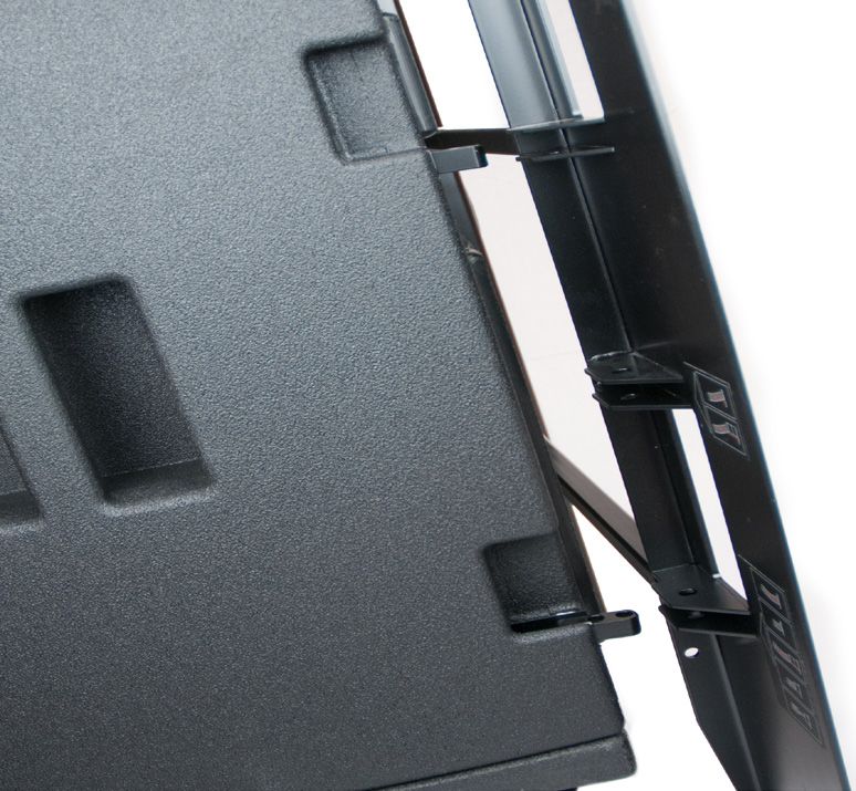
MLA MINI              USER GUIDE

                   APPROVALS

                   Safety:			                IEC60065:2002 + A1:2006

                   Environmental:            IP25 when fitted with cowl assembly (Martin Audio Pt No ASF15027)
                                             and used with mains connectors/cords rated to at least IP25.
                                             IP2X when NOT fitted with cowl assembly or not used with mains
                                             connector/cords rated to at least IP25.

                   Country of origin: United Kingdom

                   EMC Emission:		           EN55103-1:2009
                   EMC Immunity:		           EN55103-2:2009

                   FCC:			                   CFR47 Part 15B-2010

                   This is a class A product. In a domestic environment this product may cause radio interference,
                   in which case the user may be required to take adequate measures.

                               Please think of our environment.

                   When the product has reached the end of its useful life, please dispose of it responsibly through
                   a recycling centre.

MLA Mini User Guide V1.0                                                                                          3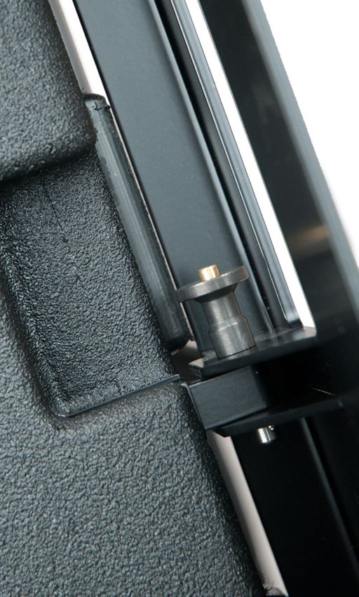
MLA MINI               USER GUIDE

SAFETY RULES

•   The MSX sub-bass/electronics unit must be powered exclusively by an earth connected
    mains socket in an electrical network compliant to IEC 364 or similar local rules. It is
    absolutely vital that the user verifies this fundamental safety requirement. If you are in any
    doubt, get the installation checked by qualified personnel before use.
•   The means of disconnection from the mains is the mains plug. We strongly recommend that
    you power the MSX from a professionally installed mains supply with an easily accessible
    on/off switch or circuit breaker. A comprehensive mains distribution system with circuit
    breakers is available from Martin Audio.
•   Before powering the MSX via the Neutrik® PowerCON TRUE1 connector, make sure that
    the unit is supplied with the correct mains operating voltage:
    •   100 – 240 V, 50 – 60 Hz
•   The MSX power section is protected by four fuses:
    •   F1, F2, F3: 3 x 3.15 A Type “T” (power amplifiers)
    •   F4: 1 x 4 A Quick blow (aux power supply)
•   Do not use this unit if the electrical power cord is frayed or broken
•   Do not remove the cover. Removing the cover will expose you to potentially dangerous
    voltages.
•   When not fitted with the optional rain cowl (Martin Audio Pt No ASF15027) or not used with
    mains connector/cords rated to at least IP25, the MSX must not be exposed to dripping,
    or splashing and no objects filled with liquids, such as vases should be placed on the
    apparatus.

4                                                                                            MLA Mini User Guide V1.0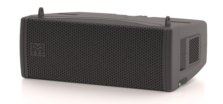
MLA MINI              USER GUIDE

                   CONTENTS
                   SAFETY INFORMATION......................................................................................2
                       Important Safety Instructions.......................................................................2
                       Approvals...................................................................................................3
                       Safety Rules...............................................................................................4

                   INTRODUCTION.................................................................................................6
                       Unpacking the units....................................................................................6

                   OVERVIEW.........................................................................................................7
                       MSX – rear panel........................................................................................8
                           Neutrik® powerCON TRUE1 connector assembly instructions.................9
                           MLA Mini connection................................................................................11

                   INSTALLATION.................................................................................................12
                       System components..................................................................................12
                       Configuration options................................................................................17
                       Choosing a preset.....................................................................................18
                       Cabling, connecting up..............................................................................22

                   RIGGING.........................................................................................................24
                       Preset 1: Pole Mount with Universal or Fixed Tilt Bracket.............................25
                       Preset 2: Pole Mount with Universal Tilt Bracket..........................................30
                       Preset 3: Pole Mount with Universal Tilt Bracket..........................................32
                       Preset 4: Ground Stack of MLA array on MSX sub........................................33
                       Preset 5: Flown Mini array with sub on floor ...............................................37
                       Preset 6: Fully-flown system......................................................................42

                   CONTACT INFO................................................................................................45

                   WARRANTY.....................................................................................................45

MLA Mini User Guide V1.0                                                                                                                5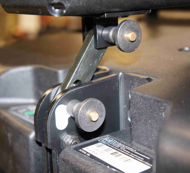
MLA MINI                USER GUIDE

INTRODUCTION

    IMPORTANT:
    This document is the User Guide for the MLA Mini Loudspeaker Array system. It is an
    abridged and edited version of the MLA Mini Advanced Manual and describes how to set
    up a basic MLA Mini system in its most common configurations, using the internal factory
    presets.
    All system owners are recommended to download and retain a copy of the MLA Mini Advanced
    Manual from http://www.martinaudio-mla.com/downloads/brochuredownloads. The manual
    contains additional information on alternative rigging possibilities and the assembly of
    larger systems. It also contains further details of the MLA Mini’s design philosophy.

UNPACKING THE UNITS
After unpacking the units, please check them carefully for any damage. If any is found,
immediately notify the carrier concerned - you, the consignee, must instigate any claim. Please
retain all packaging in case you need to return any units.

6                                                                                         MLA Mini User Guide V1.0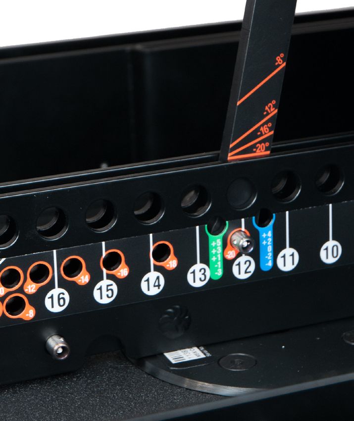
MLA MINI USER GUIDE
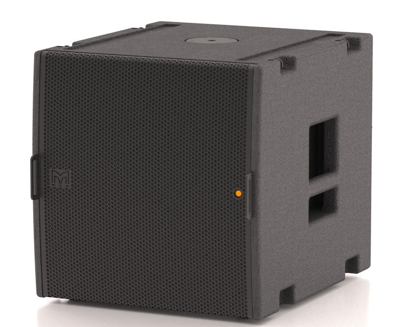
OVERVIEW
Like the MLA and MLA Compact systems from which it is derived, the MLA Mini is a precision
multi-cellular loudspeaker array designed to accurately deliver a required SPL (acoustic
loudness) within a defined area. Smaller and lighter than the MLA and MLA Compact systems,
the MLA Mini will reproduce high quality sound in smaller venues, as either a fixed or portable
installation.
The basic MLA Mini system consists of 4 MLA Mini full-range cabinets (referred to throughout
this User Guide simply as ‘Minis’), used in conjunction with a single MSX sub-woofer. This is
the minimum configuration in which the MLA Mini system can be used. The MSX incorporates
all the power amplification and other electronics for the 4 Minis as well as the sub-woofer. (Note
that the power amplification and electronics may be removed from the MSX cabinet for rack
mounting elsewhere; please refer to the Advanced Manual for full details.)
Used in stereo pairs, this minimum configuration will be adequate for many outdoor and indoor
venues with a capacity of up to approximately 250 people, and is the configuration described in
this User Guide. Additional Minis can be added, in sets of four, to create more powerful systems.
Please refer to the Advanced Manual for more details.
MLA Mini User Guide V1.0 7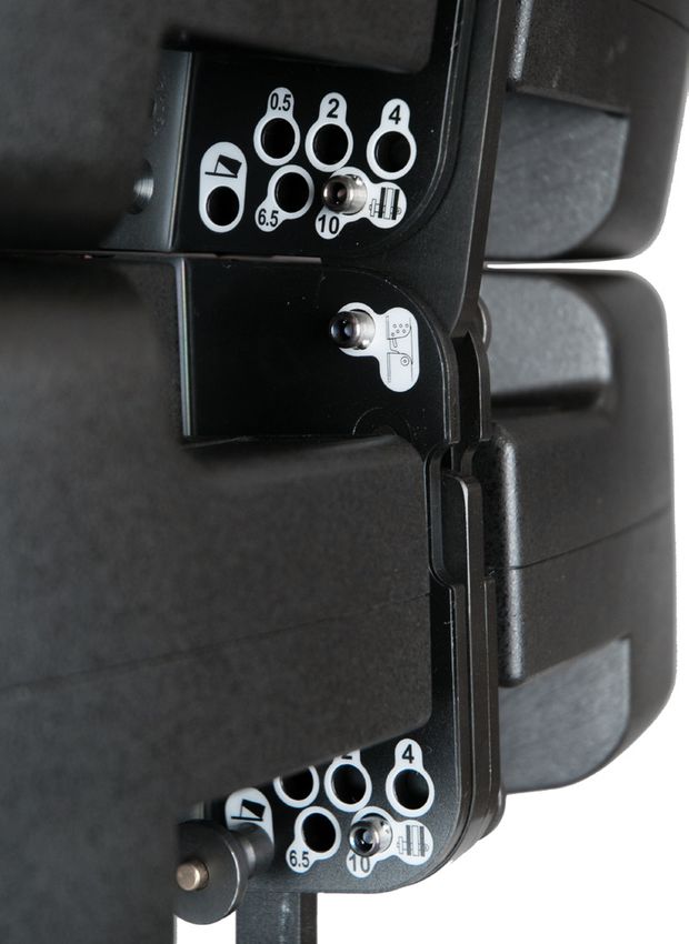
MLA MINI USER GUIDE
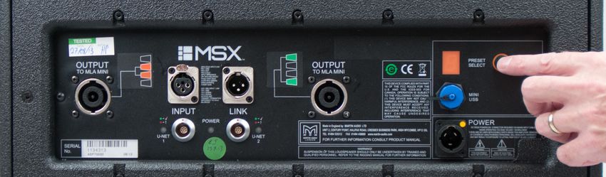
MSX – REAR PANEL
All connections for a single system comprising 4 Minis plus one MSX are made to the electronics
unit mounted in the rear of the MSX cabinet.
1 2 11 10
3 5 4 9 6 7 8
1. I NPUT – a 3-pin female XLR audio input connector. The MLA Mini system can be fed with either
balanced analogue audio or AES3 digital audio. The same connector is used for both formats,
and the analogue/digital selection is made via VU-NET control software. The default setting is
analogue. Please refer to the Advanced Manual for details about using the MLA Mini with digital
audio.
2. LINK – a 3-pin male XLR connector in parallel with the INPUT XLR. This allows the audio
input to be conveniently “daisy-chained” to further MLA Mini systems.
3. OUTPUT – two Neutrik® NL8 multi-pin connectors. Use the pre-made cable supplied with
the system to connect each OUTPUT socket to two Minis. If a longer cable is required,
please refer to the User Guide for assembly details and cable specifications. The diagrams
on the panel show clearly which Minis should be wired to each connector. The system will
not operate correctly if this wiring is not observed. See “Cabling, connecting up” on page 22.
4. U-NET 1 – a LEMO-pattern K Series network connector. This can be used to connect the
MSX to a computer running VU-NET control software. This allows the system to be tailored
more precisely to suit the venue and application in situations where a configuration other
than those provided by the internal presets is required. When using the internal presets, the
U-NET connectors may be ignored. Please see the Advanced Manual for more details.
5. U-NET 1 status – bi-colour LED indicating network status.
6. U-NET 2 – a second network port for connection to additional MLA systems. VU-NET is able
to determine the order in which cabinets are connected by analysing the inter-port latencies.
7. U-NET 2 status
8. POWER connector – a Neutrik® powerCON TRUE1 connector for AC mains input. A mating
connector is included. Pre-made power cables of various lengths are available from Martin
Audio; alternatively, If making up your own power cables, please follow the Neutrik®
assembly instructions on page 9 carefully. Please note that Neutrik tool Part No. HTAC
is NOT supplied. Tightening the connector assembly with the tool to the specified torque is
only necessary if the MSX is required to meet IP65 environmental protection conditions. If
IP65 compliance is required, please contact Martin Audio for additional information and the
necessary additional parts.
9. POWER LED – illuminates when AC power is applied to the MSX. Note that the MSX
electronics unit has no power switch; it is operative as soon as power is applied.
10. PRESET SELECT – this push-button selects one of the factory-designed internal presets,
optimising the MLA Mini system for a particular rigging configuration or required coverage
area. See page 18 for full details of each preset. The adjacent numeric display confirms
the currently loaded preset.
11. MINI USB – Type B USB port. Allows connection of a PC for system control and monitoring
purposes. For simple set-ups using the internal presets, this connector may be ignored.
Please refer to the Advanced Manual for more details.
8 MLA Mini User Guide V1.0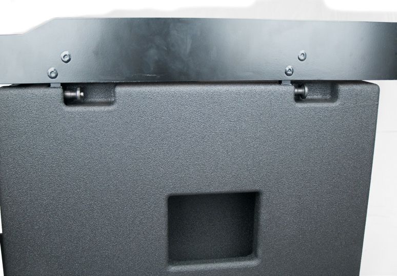
MLA MINI                USER GUIDE

                       Neutrik® powerCON TRUE1 connector assembly instructions
                       The PowerCON TRUE1 system is certified as a connector with breaking capacity according to
                       IEC60320 and VDE0625. It is intended for use as an appliance and interconnection coupler. It
                       serves to supply power to an appliance. It should be installed by qualified personnel only.

                                           A PPL IA NCE INL ET

                                                     NAC3MPX

                                             Power IN

                                        NAC3FX
                                       (Connector)

Approval based:                VDE                                            UL
                               EN 60320-1/EN60320-2-2                         UL 498 / CSA C22.2 No. 182.3

Rating:                        250 V ac / 16 A                                250 V ac / 20 A
Cable Type:                    H05VV-F3G 1.0 mm2, Length max. 2 m             SJT 3 x 12 AWG
                               H05VV-F3G 1.5 - 2.5 mm2
Strain Relief:                 White chuck                                    Black chuck
Cable O.D.:                    6.3 - 11.4 mm                                  9.5 - 12.0 mm

A   Place bushing and                                       2.                                           2.
    chuck over the cable.
                                                                                         1.
                                      1.

                                                        20 mm                                     20 mm
                                                         [0.787”]                                  [0.787”]
                                                                    8 mm                                      8 mm
                                                                    [0.32"]                                   [0.32"]

B   Prepare cable as
    shown.
                                                        PE 23 mm                                  PE 23 mm
                                                           [0.9”]                                    [0.9”]

    MLA Mini User Guide V1.0                                                                                            9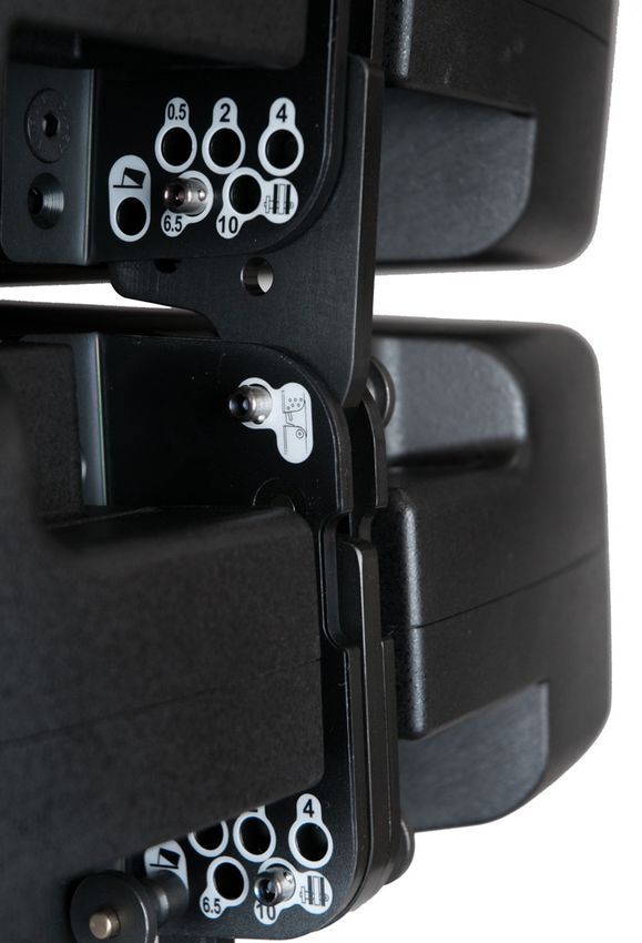
MLA MINI                         USER GUIDE

C                                                                      Slide the cable into the contacts and clamp with
                                                                       the screw.
                                                                          Wiring             VDE                 UL
                                                                           L                brown               black
                                                                           N                 blue               white
                                                                                         green / yellow         green

                                       Torque Value 0.7 Nm

                                                                  1.
D

                                                 2.

                  3.                                                   Slide insert and chuck into housing.
                                                                       Important: Align the chuck by positioning the
                                                                       nose into keyway.

                                                             5.
                                 Torque Value 2.0Nm

E                                  PRESS FIRMLY

                            4.

                                                                       Slide the cable clamp bushing up the cable and
    Wrench size
        10 mm                                                          tighten it with the tool as shown.
                                                                       (Tool available: Art. No. HTAC)

                                                 2.                    Disassembly (open twist lock):
                       1.

                                                                       1. Press with screw driver to unlock (at    )
                                                                       2. Turn bushing while still pressing locking.

10                                                                                                 MLA Mini User Guide V1.0
MLA MINI USER GUIDE
MLA MINI CONNECTION
The MLA Mini system only has one other connection. This is a Neutrik® NL4 on the Mini
cabinets themselves. Connect the cables referred to in Item [3] above here, taking care to
observe the colour coding of the connectors.
MLA Mini User Guide V1.0 11MLA MINI USER GUIDE INSTALLATION SYSTEM COMPONENTS A range of rigging accessories is available for the MLA Mini system. The accessories required for each rigging configuration differ; depending on what was specified at the time of order, you may not have all the components shown below. Before rigging the MLA Mini system for the first time in any configuration, you should first familiarise yourself with each of the various components and their purpose. Flying Frame This steel assembly is required when an MLA Mini system is to be flown using one or two chain hoists; it attaches either to the 4 x Mini array or to the MSX, depending whether the MSX is being flown as part of the array. It is also used to attach a 4 x Mini assembly to the MSX sub in a ground stack arrangement, or a 4 x Mini array directly to the Ground Stack Baseplate in a situation where the MSX sub is located separately. Clinometer A clinometer is available to check the angle at which the MLA Mini array is flown at (relative to the horizontal). It consists of a sensor (mounted within the Flying Frame) and a remote display unit. Interconnection is via a standard XLR mic cable. It is normally only supplied with the touring package. Transition Frame This is used in a flown arrangement to attach a 4 x Mini array to the underside of an MSX sub. 12 MLA Mini User Guide V1.0
MLA MINI              USER GUIDE

                   Universal tilt bracket

                   This can allow an array of 4 Minis to be fitted to the Variable Height Pole Mount at a range of tilt
                   angles. The bracket’s fixing is via a single 13 mm dia. hole, which is fitted with a boss to mate
                   with the Pole Mount. By replacing the boss with a trigger clamp, the bracket can also be used
                   inverted, to fly a single 4 x Mini array (without an MSX sub). The Flying Frame (see above) must
                   be used to fly all other system configurations.

                   Fixed Tilt Bracket

                   This is a simpler alternative to the Universal Tilt Bracket, for use with the Vertical Height Pole
                   Mount. It provides a single tilt angle (14.5°), which is correct for use with two of the presets
                   most likely to be used with pole mount configurations.

                   Variable Height Pole Mount

                   This is used to elevate an array of 4 Minis above the MSX as a single assembly. The height of the
                   array can be set to that required (either determined by the preset in use or according to the VU-
                   NET specifications) by turning the handle, and then locked in position with the integral clamp.

MLA Mini User Guide V1.0                                                                                            13
MLA MINI USER GUIDE Ground Stack Baseplate This is normally fitted to the base of the MSX for configurations where the MSX is attached to the 4 x Mini array (either directly or with the Variable Height Pole Mount) to give greater stability. It can also be used with the 4 x Mini array alone, with the Flying Frame as an intermediate adaptor. The Ground Stack Baseplate is often referred to as an “Outrigger” or “Duck’s Foot”. Ground Stack Bars These precision alignment bars are used in conjunction with the Flying Frame to define the angle between the 4 x Mini array and the MSX sub when the system is configured for ground stacking. They will also be needed when the 4 x Mini array is to be ground stacked alone. Two versions are available, long and short; the two sizes allow different ranges of angles to be set. Flying Pins The pins are used to lock the individual Mini cabinets into position at the defined inter-cabinet angle, and also to lock the 4 x Mini array to the Transition Frame or Flying Frame at the required angle. The pins are supplied with the relevant components. 14 MLA Mini User Guide V1.0
MLA MINI              USER GUIDE

                   19” rack mount kit

                   This option is required if the MSX electronics unit is to be mounted in a separate 19” equipment
                   rack.

                   Flight case for 4 Minis:

                   An optional, dedicated flightcase is available for an array of 4 Mini cabinets. This will allow safe
                   transportation and convenient rigging and de-rigging if your system is to be portable. Note that
                   all rigging accessories (except the flying pins – but see below) should be removed before stowing
                   the Minis in the flightcase for shipment.

MLA Mini User Guide V1.0                                                                                            15
MLA MINI USER GUIDE Wheelboard with castors This is a wheeled base board which is fitted to the front of the MSX sub (for speaker protection) to allow easy attachment of the Ground Stack Baseplate, and also for convenient transportation. It does not form part of an assembled system. MSX Transit Cover A tough flexible cover for the MSX with an integral plywood lid for shipping purposes. 16 MLA Mini User Guide V1.0
MLA MINI              USER GUIDE

                   CONFIGURATION OPTIONS
                   4 MLA Minis and one MSX can be rigged in four basic arrangements: two ground stacked,
                   and two flown. The option chosen for any particular situation will be largely determined by the
                   physical arrangements of the venue. Whichever arrangement is used, at least one factory preset
                   is available for optimising the system’s performance in that configuration.

                   The rigging possibilities are illustrated below; see page 24 for full details of how to perform
                   the actual physical rigging for each.

                                                                                                  Flying              Flying
                                               Universal Tilt                                     Frame               Frame
                                                 Bracket
                                                                         MINI              MINI
                                                                                                            MSX
                                                                         MINI              MINI

                                                                         MINI              MINI                         Transition
                                                                                                                          Frame
                                                                                                            MINI
                                                                         MINI              MINI
                                                                                                            MINI

                                                                                                            MINI
                              MINI
                                                                                                            MINI
                              MINI

                              MINI           MINI

                              MINI           MINI

                                             MINI
                                                                Flying
                                             MINI
                                                                Frame

                              MSX            MSX                         MSX               MSX

                           Presets 1 to 3   Preset 4                            Preset 5                   Preset 6

MLA Mini User Guide V1.0                                                                                                       17
MLA MINI USER GUIDE
CHOOSING A PRESET
The MLA Mini system comes with six factory-designed presets which optimise the system for
use in the most commonly-encountered rigging configurations. Presets are loaded by pressing
the PRESET SELECT button on the MSX rear panel; press the button until the number of the
required preset is displayed:
The diagrams below summarise the intended application for each preset. Note that the MSX-
to-Mini cabling is the same for all presets, and the audio input is set to analogue in all cases.
The diagrams indicate the various angles which will need to be set; these include the inter-
cabinet angles and the angle between the mounting and the first Mini. The selected preset
optimises the MLA Mini system for the dimensions and heights shown in the diagrams, but good
performance will still be obtained if, for example, the room is a different size or if it necessary to
use a different mounting height. Always use the preset which most closely represents the rigging
configuration you are using.
Preset 1
0.5°
6.5°
6.5°
-‐14.5°
1.57m
2m
ANALOGUE
INPUT
12m
Preset 1 optimises the system for use with the 4 x Mini array attached to the MSX sub using the
Variable Height Mount Pole. This will be an appropriate setup for venues where there is no stage;
it is assumed that the standing audience
0.5°
will be on the same level as the MSX. The system will
6.5°
be able to provide effective coverage from 2 m to 12 m from the loudspeakers.
6.5°
-‐17.5°
1.57m
2m
ANALOGUE
17m
INPUT
18 MLA Mini User Guide V1.06.5°
6.5°
-‐14.5°
MLA MINI USER GUIDE
1.57m
2m
ANALOGUE
0.5°
INPUT
12m
6.5°
6.5°
Preset 2 -‐14.5°
1.57m
0.5°
6.5°
6.5°
-‐17.5°
2m
ANALOGUE
INPUT
12m
1.57m
2m
ANALOGUE
0.5°
17m
INPUT
6.5°
6.5°
-‐17.5°
Preset 2 is similar to Preset 1, but is suited better for a seated audience over a larger area. Good
1.57m
coverage is provided between 2 m and 17 m from the loudspeakers. Note the array tilt angle
differs from that used by Preset 1.0.5°
0.5°
10°
-‐11°
2m
ANALOGUE
17m
INPUT
Preset 3
1.57m
2m
ANALOGUE
0.5°
INPUT
17m
0.5°
10°
-‐11°
1.57m
2m
ANALOGUE
INPUT
17m
Preset 3 assumes the
same
size
audience
area
as
Preset
2,
but
is
optimised
for
a standing
audience. Note the array tilt and inter-cabinet angles differ again.
MLA Mini User Guide V1.0 19MLA MINI USER GUIDE
Preset 4
0.5°
6.5°
-‐20°
10°
1.81m
ANALOGUE
INPUT
1.2m
2m
0.5°
12m
6.5°
-‐20°
10°
This preset is suitable for a ground stack-‐7°
system mounted on a stage approximately 1.2 m high.
Here the 4ANALOGUE
x Mini array H10
is mounted on the MSX sub using the Flying Frame. The long Ground
1.81m
0.5°
Stack Bar provides
INPUT
the overall array4°
tilt angle. The system will provide coverage between 2 m
1.2m
and 12 m from the loudspeakers. 10°
2m
12m
Preset 5
2.38m
2m
-‐7°
ANALOGUE
12m
INPUT
H10
0.5°
4°
10°
ANALOGUE
INPUT
-‐7.5°
2.38m
H13
0.5°
4°
10°
2m
ANALOGUE
12m
INPUT
2.38m
ANALOGUE
INPUT
This preset should be used when the 2m
4 x-‐7.5°
Mini array is flown, with the MSX sub remaining on the
floor. The preset is most effective with the bottom array cabinet H13
12m
2.38 m above floor level, and for
a standing audience between 2 m and 12 m from the loudspeakers. The Flying Frame may be
used to hang the array and define the basic 0.5°
tilt angle, or the Universal Tilt Bracket may be used
if the 4 x Mini array is to be suspended 4°
from a rigging pole or truss. Note however that when
using the Universal Tilt
Bracket
10°
ONLY
a
single
4
x
Mini
array
can
be
suspended.
Do
not use
it to
suspend Mini arrays in excess of four cabinets, nor for fully-flown configurations where the MSX
sub is also flown (see Preset 6).
2.38m
2m
12m
20 MLA Mini User Guide V1.0H10
0.5°
4°
10°
MLA MINI USER GUIDE
2.38m
2m
Preset 6ANALOGUE
12m
INPUT
ANALOGUE
INPUT
-‐7.5°
H13
0.5°
4°
10°
2.38m
2m
12m
This preset applies to
a
fully-flown
configuration;
the
ground
stack
configuration
is effectively
‘inverted’, with the MSX sub at the top of the array. The Flying Frame and Transition Frame are
both required to achieve this configuration. The audience coverage is the same as for Preset 5.
Summary of Presets:
Preset Rigging Location Coverage Audience
1 Pole mount Floor-standing 2 – 12 m Standing
2 Pole mount Floor-standing 2 – 17 m Seated
3 Pole mount Floor-standing 2 - 17 m Standing
4 Ground stack On stage 2 – 12 m Standing
5 Flown array Sub on floor, array flown 2 – 12 m Standing
6 Fully flown Fully flown 2 – 12 m Standing
MLA Mini User Guide V1.0 21MLA MINI USER GUIDE
CABLING, CONNECTING UP
The electrical connections for a single 4 x Mini array plus an MSX sub are straightforward.
6
Electrical Safety UL 60065
PRESET
OUTPUT PUSH
ANALOGUE INPUT/LINK
PIN 1 GND
OUTPUT SELECT
TO MLA MINI PIN 2 HOT
PIN 3 COLD
INPUT IMPEDANCE
TO MLA MINI
20K Ohms BALANCED
Always check signal
source drive capability
2 1 before parallelling
multiple inputs THIS DEVICE COMPLIES WITH PART
3 15 OF THE FCC RULES FOR THE
AES / EBU INPUT / LINK
PIN 1 GND U.S. AND THE ICES-003 FOR
PIN 2 SIGNAL CANADA. OPERATION IS SUBJECT
PIN 3 SIGNAL
RECEIVE AND TO THE FOLLOWING CONDITIONS: MINI
(1) THIS DEVICE MAY NOT CAUSE
NEUTRIK
TRANSMIT TERMINATION
IMPEDANCE 110 Ohms
NEUTRIK HARMFUL INTERFERENCE, AND (2)
USB
BALANCED
THIS DEVICE MUST ACCEPT ANY
INTERFERENCE RECEIVED,
INPUT LINK
-‐14.5°
INCLUDING INTERFERENCE THAT
MAY CAUSE UNDESIRED
OPERATION.
! POWER ! POWER
Made in England by MARTIN AUDIO LTD IEC 60320 POWERCON CONNECTOR REQUIRED ON MAINS INPUT CABLE.
UNIT 2, CENTURY POINT, HALIFAX ROAD, CRESSEX BUSINESS PARK, HIGH WYCOMBE, HP12 3SL MAINS OPERATING VOLTAGE 100-240V ~50-60Hz 900W
THERE ARE NO USER SERVICEABLE PARTS INSIDE THIS AMPLIFIER. REMOVAL
TEL 01494 535312 FAX 01494 438669 www.martin-audio.com OF COVERS BY UNAUTHORISED PERSONNEL WILL INVALIDATE WARRANTY
U-NET U-NET AND MAY RESULT IN EXPOSURE TO LETHAL HIGH VOLTAGE AND CURRENT.
FOR FURTHER INFORMATION CONSULT PRODUCT MANUAL
1 2
SERIAL WARNING! WARNING CAUTION
No. SUSPENSION OF THIS LOUDSPEAKER SHOULD ONLY BE UNDERTAKEN BY TRAINED AND
LIECHTENSTEIN
THIS EQUIPMENT
MUST BE EARTHED
RISK OF ELECTRIC
SHOCK DO NOT OPEN
IP25
QUALIFIED PERSONNEL. REFER TO THE RIGGING MANUAL FOR FURTHER INFORMATION
1. AC Mains – connect the power supply cable to the Neutrik® PowerCON TRUE1 connector
on the rear panel of the MSX sub. Do not connect the other end of the cable to a live AC
supply at this stage.
2. Connect the amplifier outputs to the MLA Mini cabinets using the pre-made cable
assembly supplied (if length permits - configuration-dependent. Some configurations
will require longer cables). Note the colour-coding (orange and green); also note the
wiring diagram on the MSX rear panel adjacent to each of the OUTPUT connectors.
Plug the orange NL8 connector into the left-hand OUTPUT socket. Plug the green NL8 ANALOGUE
connector into the right-hand OUTPUT socket. Note that the other ends of the cable haveINPUT
different lengths of ‘tail’. This is to identify which cable connects to which cabinet.
IMPORTANT: The wiring instructions differ between ground stack configurations and flown
configurations. Use the correct set of instructions for the arrangement you are using.
Ground stack configurations:
• Plug the orange-coded NL4 with the shorter tail into Cabinet 2 (the
second cabinet from the bottom of the array)
• Plug the orange-coded NL4 with the longer tail into Cabinet 3 (the
third cabinet from the bottom of the array) -‐17.5°
• Plug the green-coded NL4 with the shorter tail into Cabinet 1 (the
bottom cabinet in the array)
• Plug the green-coded NL4 with the longer tail into Cabinet 4 (the top
cabinet in the array)
ANALOGUE
INPUT
22 MLA Mini User Guide V1.0MLA MINI USER GUIDE
Flown configurations:
• Plug the orange-coded NL4 with the shorter tail into Cabinet 2 (the
second cabinet from the top of the array)
H10
• Plug the orange-coded NL4 with the longer tail into Cabinet 3 (the
third cabinet from the top of the array)
• Plug the green-coded NL4 with the shorter tail into Cabinet 1 (the top
cabinet in the array)
• Plug the green-coded NL4 with the longer tail into Cabinet 4 (the
bottom cabinet in the array)
3. Connect the audio source (mixing console output) to the INPUT connector.
Ensure that the mixing console main output is muted or faded down.
4. Apply power to the MSX electronics rack; check that the POWER LED is
illuminated.
5. Select the preset to be used using the PRESET SELECT button.
6. Gradually raise the output level of the mixing console. ANALOGUE
INPUT
ANALOGUE
INPUT
H13
MLA Mini User Guide V1.0 23MLA MINI USER GUIDE
RIGGING
This section of the User Guide covers the mechanical aspects of assembling the various
components of the MLA Mini system into the configuration required.
The rigging details here are limited to those required to achieve the arrangements necessary
for correct operation of the system using the six factory presets. Please refer to the Advanced
Manual for full details of other rigging possibilities, including all MLA Mini system configurations
which use more than 4 Minis and one MSX sub.
The six presets cover four possible rigging arrangements for 4 MLA Mini cabinets and one
MSX sub; the components required for each are summarised in the table below. Note that the
component count applies to a single system; for stereo, the quantities should be doubled.
Universal Ground Ground Flying
Pole Fixed Tilt Transition Flying
Component Tilt Stack Stack Bar Pins
Mount Bracket Frame Frame
Bracket Baseplate (long) Required
Preset Configuration
1&2 Pole Mount 1 1 1 21
3 Pole Mount 1 1 1 1 21
4 Ground stack 1 1 1 25
5* Flown array 1 17
(Flying Frame)/
Floor sub
Flown array 1 17
(Universal Tilt
Bracket)/Floor
sub
6 Fully flown 1 1 24
*The configuration for Preset 5 can be flown either using the Flying Frame or the Universal Tilt Bracket inverted.
24 MLA Mini User Guide V1.0MLA MINI USER GUIDE
PRESET 1: POLE MOUNT WITH UNIVERSAL OR FIXED TILT BRACKET
Shown using the Fixed Tilt Bracket
Step1: Start with the MSX sub face down on its wheelboard. Rotate the four dropdown brackets
located in the base of the MSX so they are protruding outwards. Attach the Ground Stack
Baseplate to the bottom of the MSX cabinet by mating these dropdown brackets with the holes
in the baseplate box sections as shown. Use the front location as indicated on the baseplate
membrane for this configuration (the rear location is only needed for larger configurations).
With the MSX on its wheelboard and the front edge of the Baseplate on the floor, the dropdown
brackets should align with the correct holes. Secure all four dropdown brackets with Flying Pins.
MLA Mini User Guide V1.0 25MLA MINI USER GUIDE Step 2: Rotate the MSX and Ground Stack Baseplate through 90° so that the assembly is standing on the Baseplate. Remove the wheelboard. Take the Pole Mount and ensure that the pole is fully retracted. Screw the pole securely into the threaded plate on the top of the MSX. Step 3: As the Bracket Tilt Angle for Preset 1 is 14.5°, either the Universal Tilt Bracket or the Fixed Tilt Bracket may be used. Attach the chosen bracket to the top of the telescopic pole and secure by tightening the boss onto the pole using the knob. 26 MLA Mini User Guide V1.0
MLA MINI              USER GUIDE

                   Step 4a (with Universal Tilt Bracket): Lift the first MLA Mini cabinet onto the Universal Tilt
                   Bracket. The lugs on the ends of the main cross-arm should mate with the slots in the front
                   corners of the cabinet. Secure these points with flying pins. Attach the rear lug of the bracket to
                   the Ground Stack hole (marked with a        ) in the cabinet’s rear mounting plate. Secure with a
                   Flying Pin. Using the rear adjustment knob, set the tilt angle to 14.5°; the angle can be seen by
                   observing the calibration hole at the right-hand side.

                   Step 4b (with Fixed Tilt Bracket): Lift the first MLA Mini cabinet onto the bracket. The lugs on
                   the ends of the main cross-arm should mate with the slots in the front corners of the cabinet.
                   Secure these points with Flying Pins. Attach the Tilt Bracket Swing Arm to the rear of the tilt
                   bracket in the Ground Stack hole (marked with a   ) and secure with the Flying Pin supplied.
                   Ensure the swing arm is pointed upwards as shown.

MLA Mini User Guide V1.0                                                                                           27
MLA MINI USER GUIDE Step 5: Lift the next cabinet on top of the previous one and secure both the front corners with further Flying Pins. At the rear, remove the Flying Pin used to stow the rear mounting plate so that it drops down and engages with the slot in the lower cabinet’s bracket. Secure this with the Flying Pin.Raise the upper cabinet to set the angle between the cabinets by fitting a Flying Pin in the hole marked “6.5” on the rear bracket. This gives the correct inter-cabinet angle required by Preset 1. Step 6: Repeat Step 5 twice to add the two remaining MLA Mini cabinets, while referring to the Preset diagrams starting on page 18 and the table below. Note that the inter-cabinet angles for cabinets 2 to 3 and 3 to 4 differ. Take care to set the correct angles. Step 7: The connections to the 4 x Mini array (see page 22) are most conveniently made at this stage. Step 8: Depress the safety catch to unlock the height adjustment, and turn the handle to raise the telescopic pole mount so that the front lower edge of the bottom Mini is approximately 1.57 m above the level that the MSX is standing on. Lock it in place by tightening the knob on the opposite side of the pole from the handle. 28 MLA Mini User Guide V1.0
MLA MINI              USER GUIDE

                   Summary of angles (Presets 1):

                                                                           Preset 1

                                     Bracket tilt angle                    14.5°

                                                          Cabinets 1 & 2   6.5°
                                     Inter-cabinet
                                                          Cabinets 2 & 3   6.5°
                                     angles
                                                          Cabinets 3 & 4   0.5°

MLA Mini User Guide V1.0                                                              29
MLA MINI USER GUIDE PRESET 2: POLE MOUNT WITH UNIVERSAL TILT BRACKET The rigging procedure for Preset 2 is very similar to that for Preset 1, with the exception that the Universal Tilt Bracket must be used, as the overall array tilt is 17.5°, an angle not achievable with the Fixed Tilt Bracket. Step1: As for Preset 1 Step 2: As for Preset 1 Step 3: As the Bracket Tilt Angle for Preset 2 is 17.5°, the Universal Tilt Bracket must be used. Attach the bracket to the top of the telescopic pole and secure by tightening the boss onto the pole using the knob. Assemble the Universal Bracket for pole mount operation as described in its accompanying assembly instructions. Step 4: Lift the first MLA Mini cabinet onto the Universal Tilt Bracket. The lugs on the ends of the main cross-arm should mate with the slots in the front corners of the cabinet. Secure these points with flying pins. Attach the rear lug of the bracket to the Ground Stack hole (marked with a ) in the cabinet’s rear mounting plate. Secure with a Flying Pin. Using the rear adjustment knob, set the tilt angle to 17.5°; the angle can be seen by observing the calibration hole at the right-hand side. 30 MLA Mini User Guide V1.0
MLA MINI              USER GUIDE

                   Step 5: As for Preset 1.

                   Step 6: Repeat Step 5 twice to add the two remaining MLA Mini cabinets, while referring to the
                   Preset diagrams starting on page 18 and the table below. Note that the inter-cabinet angles
                   for cabinets 2 to 3 and 3 to 4 differ. Take care to set the correct angles.

                   Step 7: The connections to the 4 x Mini array (see page 22) are most conveniently made at
                   this stage.

                   Step 8: As for Preset 1.

                   Summary of angles (Preset 2):

                                                                                 Preset 2

                                         Bracket tilt angle                      17.5°

                                                              Cabinets 1 & 2     6.5°
                                         Inter-cabinet
                                                              Cabinets 2 & 3     6.5°
                                         angles
                                                              Cabinets 3 & 4     0.5°

MLA Mini User Guide V1.0                                                                                      31
MLA MINI USER GUIDE
PRESET 3: POLE MOUNT WITH UNIVERSAL TILT BRACKET
Steps 1 and 2 are as for Presets 1 and 2.
Step 3: As the Bracket Tilt Angle for preset 3 is 11°, the Universal Tilt Bracket must be fitted to
the Pole Mount. Attach the Bracket to the top of the telescopic pole and secure by tightening
the boss onto the pole using the knob.
Step 4: Proceed as Step 4a for Preset 1 above. For Preset 3, however, set the Bracket Tilt Angle
to 11°.
Steps 5 to 8: Follow the corresponding instructions for Presets 1 and 2. However, note the
different inter-cabinet angles, and fit the Flying Pins into the drop-down brackets accordingly to
achieve the correct angles.
Summary of angles (Preset 3):
Preset 3
Bracket tilt angle 11°
Cabinets 1 & 2 10°
Inter-cabinet
Cabinets 2 & 3 0.5°
angles between:
Cabinets 3 & 4 0.5°
32 MLA Mini User Guide V1.0MLA MINI USER GUIDE
PRESET 4: GROUND STACK OF MLA ARRAY ON MSX SUB
Step1: Start with the MSX sub face down on its wheelboard. Rotate the four dropdown brackets
in the base of the MSX so they are protruding outwards. Attach the Ground Stack Baseplate
to the bottom of the MSX cabinet by mating these dropdown brackets with the holes in the
baseplate box sections as shown. Refer to the diagram on the base plate membrane; note there
are two mounting positions for the MSX. In this case, the MSX’s front dropdowns should mate
with the pair of slots nearer the front of the baseplate. With the MSX on its wheelboard and
the front edge of the Baseplate on the floor, the dropdowns should align with the correct holes.
Secure all four dropdown brackets with Flying Pins.
MLA Mini User Guide V1.0 33MLA MINI USER GUIDE Step 2: Rotate the MSX and Ground Stack Baseplate through 90° so that the assembly is standing on the Baseplate. Remove the wheelboard. Place the Flying Frame on top of the MSX cabinet as shown and secure the dropdown brackets using four Flying Pins. Step 3: For Preset 4 the required angle between the sub and the bottom Mini is 20°, so the Long Ground Stack Bar must be used between the cabinet and the Flying Frame. Fit the lower end of the bar into the Flying Frame at the 20° mark and secure with a Flying Pin. 34 MLA Mini User Guide V1.0
Step 4: Next, raise the two front lugs of the Flying Frame to their upright position, and secure.
These will mate with the front slots of the first Mini. Fit the first MLA Mini cabinet onto the
Flying Frame, locking the two front slots into place with Flying Pins. Note that the front of the
Flying Frame should be flush with the lower front edge of the cabinet.

Step 5: Lift the rear of the cabinet and attach the top end of the Ground Stack bar to the rear
bracket by matching the Ground Stack symbol        on the bar to the Ground Stack symbol on the
bracket. Secure with a Flying Pin.
MLA MINI                USER GUIDE

Step 6: Lift the next cabinet on top of the previous one and secure both the front corners with
further Flying Pins. At the rear, rotate the upper cabinet’s flip-down bracket so that it engages
with the slot in the lower cabinet, and set the angle between the first and second cabinets to
10° by fitting a Flying Pin in the hole marked “10” on the lower bracket. This gives the correct
inter-cabinet angle required by Preset 4.

Step 7: Repeat Step 6 twice to add the two remaining MLA Mini cabinets, while referring to the
Preset diagrams on page 20 and the table below. Take care to set the correct angles.

Step 8: The connections to the 4 x Mini array (see page 22) are most conveniently made at
this stage.

Summary of angles (Preset 4):

                                                               Preset 4

                      Bracket tilt angle                       20°

                                           Cabinets 1 & 2      10°
                      Inter-cabinet
                                           Cabinets 2 & 3      6.5°
                      angles between:
                                           Cabinets 3 & 4      0.5°

36                                                                                          MLA Mini User Guide V1.0
MLA MINI USER GUIDE
PRESET 5: FLOWN MINI ARRAY WITH SUB ON FLOOR
When the MSX sub is used in isolation, as with Preset 5, there is no necessity to fit the Ground
Stack Baseplate to it.
There are two methods of suspending an array of 4 MLA Minis:
• with the Flying Frame and a chain hoist
• with the Universal Tilt Bracket and a scaffold clamp (or similar single-point fixing)
The Flying Frame allows the 4 x Mini array to be suspended using either one or two chain
hoists. The Flying Frame may be fitted with a clinometer to allow the array tilt to be accurately
measured.
The Universal Tilt Bracket may be used inverted (relative to its use with the Pole Mount), with a
standard Trigger Clamp attached to its 13 mm fixing hole instead of the boss that secures it to
the Pole Mount. This is the simpler method, and is ideal if a scaf pole or truss is available. Note
that 4 x Minis is the ONLY MLA configuration that may be flown using this method; all other
configurations MUST employ the Flying Frame.
Note that the order of cabinets in a flown array is effectively reversed relative to their order in a
Pole Mount or Ground Stack configuration. Thus the top cabinet in the array is assembled first.
Step 1: Start with the four MLA Mini cabinets face down on their flightcase base. The cabinets
should be locked together with Flying Pins at the front and rear, with the rear pins in the ’0.5’
position so that the four cabinets form a “flat” array. Attach the Flying Frame to the top cabinet,
noting that the cabinet’s top lugs mate with slots in the base of the Flying Frame. Use two Flying
Pins to secure the front corners. Note that there are two available mounting positions on the
frame; for this Preset, ensure that the front of the flying frame is flush with the bottom front edge
of the cabinets. (The second mounting position is only used with larger arrays.)
MLA Mini User Guide V1.0 37MLA MINI USER GUIDE Step 2a (using Flying Frame): Unlatch the rear dropdown bracket from the centre of the Flying Frame. Note that there are two of these; in this case, use the one which pivots at hoist point 13. This will mate with the upper section of the rear bracket of the first Mini. Secure with a Flying Pin. Step 2b (using Universal Tilt Bracket): Remove the Pole Mount boss from the Universal Tilt Bracket (if one is attached). Attach a standard Trigger Clamp to the bracket’s fixing hole with an M12 (½”) nut and bolt. 38 MLA Mini User Guide V1.0
MLA MINI              USER GUIDE

                   Attach the Universal Tilt Bracket to the top of the first Mini. The lugs on the ends of the main
                   cross-arm should mate with the slots in the front corners of the cabinet. Secure these points
                   with flying pins. Attach the rear lug of the bracket to the Ground Stack hole in the cabinet’s rear
                   mounting plate. Secure with a Flying Pin. Using the rear adjustment knob, set the tilt angle to
                   7°; the angle can be seen by observing the calibration hole at the right-hand side.

                   Step 3a (using Flying Frame): Attach the chain hoist to the H10 suspension hole of the Flying
                   Frame and begin to raise the array up off the flight case base. As the array rises, insert Flying
                   Pins in the rear brackets to define the inter-cabinet angles according to the diagram on page
                   20 and the table below.

MLA Mini User Guide V1.0                                                                                           39
MLA MINI USER GUIDE Step 3b (using Universal Tilt Bracket): Lift the array and suspend it from the truss or scaf pole by the trigger clamp. How this is best achieved will depend on the venue and other circumstances on the day. The easiest solution, wherever possible, is to lower the scaf pole or truss section from which the array is to be flown to a sensible working height, attach the array and raise the pole/truss back up to the height specified by the Preset (see table). If this option is not available, a mechanical hoist (e.g. Genie or picker) or adequate manpower can be employed. Ensure that the T-clamp is tightened. Set the Bracket Tilt Angle to 7°; the angle can be seen by observing the calibration hole at the right- hand side. Step 4: If easy access is available to the array at its flown height, it is probably better to leave connecting the cabinets up (see page 22) until the array has been raised to height, as hanging cables may constitute a hazard. However, if it is easier to connect up at ground level, perform this step next. Note that the supplied NL8-to-NL4 cables will not be long enough for this configuration, and two standard NL8-to-NL8 cables of the appropriate length and NL8 couplers will need to be added. Step 5: As the array is being raised, and as the cabinets reach a suitable height, set each of the inter-cabinet angles in turn. Refer to the Preset diagrams at page 20 and the table below. Step 6a (using Flying Frame): Continue raising the array on the hoist until the lower edge of the bottom MLA Mini cabinet is approximately 2.38 m above floor level. If the Flying Frame tilt angle is fitted with a clinometer, the tilt can be checked with the clinometer display. With a single hoist attached as described in Step 3a, the array’s centre of gravity should set the tilt at the correct angle. If using two hoists, adjust the rear relative to the front to set the back-to-front tilt to 7°. 40 MLA Mini User Guide V1.0
MLA MINI              USER GUIDE

                   Summary of angles (Preset 5):

                                                                           Preset 5

                                     Flying Frame tilt angle               7°

                                                          Cabinets 1 & 2   0.5°
                                     Inter-cabinet
                                                          Cabinets 2 & 3   4°
                                     angles between:
                                                          Cabinets 3 & 4   10°

MLA Mini User Guide V1.0                                                              41
MLA MINI USER GUIDE PRESET 6: FULLY-FLOWN SYSTEM Step 1: With the MSX sub on its wheelboard, begin by attaching the Flying Frame to the cabinet. Extend the four dropdown brackets and engage them into the four slots in the top of the sub. The front edge of the Flying Frame should be aligned with the front face of the MSX. Secure the dropdown brackets in place with four Flying Pins. Step 2: Attach the chain hoist to the H13 suspension hole of the Flying Frame and raise the MSX upwards. Remove the wheelboard when it is clear of the ground. 42 MLA Mini User Guide V1.0
MLA MINI              USER GUIDE

                   Step 3: Assemble the 4 x MLA Mini array face down on their flightcase base. Attach the Transition
                   Frame to the upper MLA Mini cabinet with Flying Pins. The frame connects at three points: two
                   are the cabinet’s front location points, which engage with slots in the frame; the other is at the
                   rear, where the swinging arm can mate with the upper section of the cabinet rear bracket in three
                   positions to produce an angle between the Transition frame and the Mini of 0°, 2.5° or 5°; for
                   Preset 6, it should be set at 0°

                   Step 4: Position the Transition Frame below the suspended MSX sub. Attach the Transition
                   Frame to the two dropdown brackets on the bottom rear of the MSX cabinet. Secure with two
                   Flying Pins.

MLA Mini User Guide V1.0                                                                                          43
MLA MINI USER GUIDE
Step 5: Gradually raise the chain hoist; this will swing the Mini array up and free of the flightcase
base. Steady the assembly as this happens. When the array is completely free, push it forwards
so that the front location points of the Transition Frame are able to engage with the front
dropdowns of the MSX. Secure these points with two more Flying Pins.
Step 6: As the array is raised, set the inter-cabinet angles of the Minis according to the table
below and the diagram at page 21. Remember that when flown, Cabinet 1 is at the top,
nearest to the MSX sub; Cabinet 4 is the lowest.
Step 7: The connections between the MSX and the Minis (see page 22) are most conveniently
made at this stage. In this case, the supplied cable can be used as the MSX is adjacent to the
Minis. AC mains, the analogue audio input and any network in use should also be connected at
this time.
Step 8: Continue raising the array on the chain hoist until the lower edge of the bottom Mini is
approximately 2.38 m above floor level. If employing two hoists to fly the array, the tilt should
now be adjusted to 7.5°. This can be checked by using the clinometer display if one is fitted.
Summary of angles (Preset 6):
Preset 6
Flying Frame tilt angle 7.5°
Transition Frame angle 0°
Cabinets 1 & 2 0.5°
Inter-cabinet
Cabinets 2 & 3 4°
angles between:
Cabinets 3 & 4 10°
44 MLA Mini User Guide V1.0MLA MINI USER GUIDE
CONTACT INFO
Martin Audio Ltd.
Century Point
Halifax Road
Cressex Business Park
High Wycombe
Buckinghamshire
HP12 3SL
United Kingdom
Tel: +44 (0) 1494 535312
Fax: +44 (0) 1494 438669
technical@martin-audio.com
WARRANTY
Martin Audio Loudspeaker Systems are warranted against manufacturing defects in materials or
craftsmanship over a period of 5 years from the date of original purchase.
During the warranty period Martin Audio will, at its discretion, either repair or replace products
which prove to be defective provided that the product is returned in its original packaging,
shipping prepaid, to an authorised Martin Audio service agent or distributor.
Martin Audio Ltd. cannot be held responsible for defects caused by unauthorised modifications,
improper use, negligence, exposure to inclement weather conditions, act of God or accident, or
any use of this product that is not in accordance with the instructions provided by Martin Audio.
Martin Audio is not liable for consequential damages.
This warranty is exclusive and no other warranty is expressed or implied. This warranty does not
affect your statutory rights.
Martin Audio MSX Amplifier modules are warranted against manufacturing defects in materials
or craftsmanship over a period of 1 year from the date of original purchase.
During the warranty period Martin Audio will, at its discretion, either repair or replace products
which prove to be defective provided that the product is returned in its original packaging,
shipping prepaid, to an authorised Martin Audio service agent or distributor.
Martin Audio Ltd. cannot be held responsible for defects caused by unauthorised modifications,
improper use, negligence, exposure to inclement weather conditions, act of God or accident, or
any use of this product that is not in accordance with the instructions provided by Martin Audio.
Martin Audio is not liable for consequential damages.
This warranty is exclusive and no other warranty is expressed or implied. This warranty does not
affect your statutory rights.
E&OE
MLA Mini User Guide V1.0 45MLA MINI USER GUIDE 46 MLA Mini User Guide V1.0
MLA MINI              USER GUIDE

MLA Mini User Guide V1.0           47
Martin Audio Limited

Century Point

Halifax Road

Cressex Business Park

High Wycombe                      UK                                              NORTH AMERICA

Buckinghamshire                   Telephone: +44 (0)1494 535312                   Telephone: 519 747 5853

HP12 3SL                          Facsimile: +44 (0)1494 438669                   Facsimile: 519 747 3576

England                           E-mail: info@martin-audio.com                   E-mail: infona@martin-audio.com

All information is Copyright © 2013 Martin Audio Ltd.
Martin Audio, the Martin Audio logo and Hybrid are registered trademarks of Martin Audio Ltd. in the United Kingdom,
United States and other countries; all other Martin Audio trademarks are the property of Martin Audio Ltd.
www.martin-audio.com
www.martinaudio-mla.com
You can also read