Visual Information Requirements for Remotely Supervised Autonomous Agricultural Machines - MDPI
←
→
Page content transcription
If your browser does not render page correctly, please read the page content below
applied
           sciences
Article
Visual Information Requirements for Remotely
Supervised Autonomous Agricultural Machines
Uduak Edet and Daniel Mann *
 Department of Biosystems Engineering, University of Manitoba, Winnipeg, MB R3T 5V6, Canada;
 edetu@myumanitoba.ca
 * Correspondence: Danny.Mann@umanitoba.ca; Tel.: +1-204-474-7149

 Received: 26 March 2020; Accepted: 14 April 2020; Published: 17 April 2020

 Abstract: A study to determine the visual requirements for a remote supervisor of an autonomous
 sprayer was conducted. Observation of a sprayer operator identified 9 distinct “look zones” that
 occupied his visual attention, with 39% of his time spent viewing the look zone ahead of the sprayer.
 While observation of the sprayer operator was being completed, additional GoPro cameras were
 used to record video of the sprayer in operation from 10 distinct perspectives (some look zones
 were visible from the operator’s seat, but other look zones were selected to display other regions
 of the sprayer that might be of interest to a sprayer operator). In a subsequent laboratory study,
 29 experienced sprayer operators were recruited to view and comment on video clips selected from
 the video footage collected during the initial ride-along. Only the two views from the perspective of
 the operator’s seat were rated highly as providing important information even though participants
 were able to identify relevant information from all ten of the video clips. Generally, participants
 used the video clips to obtain information about the boom status, the location and movement of the
 sprayer within the field, the weather conditions (especially the wind), obstacles to be avoided, crop
 conditions, and field conditions. Sprayer operators with more than 15 years of experience provided
 more insightful descriptions of the video clips than their less experienced peers. Designers can
 influence which features the user will perceive by positioning the camera such that those specific
 features are prominent in the camera’s field of view. Overall, experienced sprayer operators preferred
 the concept of presenting visual information on an automation interface using live video rather than
 presenting that same information using some type of graphical display using icons or symbols.

 Keywords: agricultural machine; autonomous; remote supervision; sprayer; automation interface

1. Introduction
     The era of autonomous agricultural machines (AAMs) seems to be just around the corner.
Engineers and researchers are working diligently to design AAMs that will enable farmers to increase
the productivity of their operations. When contemplating the incorporation of automation into an
existing machine, [1] presented a model that can be used by design engineers to identify which functions
should be automated. Their model is based on the four-stage model of human information processing
and proposes that automation can be applied to four distinct types of functions: information acquisition,
information analysis, decision and action selection, and action implementation. The engineer’s task is
to assign the appropriate level of automation (ranging from manual to fully autonomous) for each
of the four distinct types of functions. An AAM is likely to have a high level of automation for
each of these independent types of functions. Despite the fact that an AAM is designed to automate
information acquisition and analysis (using various sensors), to automate decision-making (through
well-designed programming or machine learning approaches), and to automate action implementation
(through various actuators linked to on-board sensors), it is imperative that design engineers do not

Appl. Sci. 2020, 10, 2794; doi:10.3390/app10082794                            www.mdpi.com/journal/applsci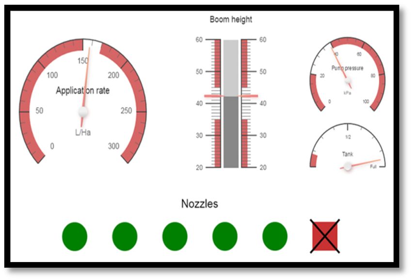
Appl. Sci. 2020, 10, 2794                                                                            2 of 16

forget to consider human interaction with the automation. Although it might be tempting to think
of AAMs working in the field as independent of any human interaction, it is prudent to consider a
larger system that is composed of the AAM working autonomously in the field and the human who
will be monitoring its operation from a location that is remote from the field [2–4]. From this larger
system perspective, the human supervisor, who is interested in both the status and progress of the
AAM, will remotely supervise the AAM through some type of display, which can be aptly described as
an “automation interface”.
       It has been observed that humans face difficulty in maintaining a high level of awareness of system
states when the system is under the control of either another human or of automation [5]. This decline
in situation awareness is problematic for the human responsible for supervising the AAM; the authors
of [6] advised that special attention must be given to the design of the automation interface to minimize
such reduction in situation awareness. The ultimate productivity of such a human–machine system
will depend on the type of information that is presented to the supervisor through an automation
interface and the ability of the supervisor to efficiently and effectively glean the information from the
interface. Therefore, great importance must be placed on the design of the automation interface so that
the entire human automation system can be optimized.
       Previous studies [7–9] have suggested that video footage is essential to supervisors when
monitoring a machine remotely. The authors of [10] proposed a system architecture to enable control
of an autonomous tractor that included a “coordinating process”, which was to be handled by a
coordinator located remotely in a farm office. They proposed the phrase “tractor mimic display” for
the computer interface that would be used by the coordinator to obtain tractor status information [10],
also suggesting that the mimic display would incorporate a “real-time video link to steerable on-board
cameras” to allow the coordinator to have “a better understanding of the tractor’s environment.”
Several other research groups have described similar concepts, where a remote supervisor has some
level of control over one or more AAMs [7,11,12]. The authors of [10] stated that the inclusion of
video will enable the supervisor to better understand the tractor’s environment, while the authors
of [13] reported that a large majority of participants identified the presence of live video as being
important for understanding machine functions. Furthermore, participants were more secure in their
interpretation of visual information if live video was present [13]. Thus, there is a growing body of
evidence to suggest that real-time visual information in the form of live video is an essential element
for an automation interface.
       With these potential benefits, it is necessary to know which regions of the agricultural machine
and its surrounding environment should be targeted by visual sensors. The authors of [14] recognized
seven “look zones” (or areas the operator is expected to visually monitor during operation) for a
seeding machine, labeled as: (i) forward, (ii) right side, (iii) planter, (vi) planter edge, (v) display
X (located at the top right corner from the operator’s seated position), (vi) display Y (located close
to the right arm rest), and (vii) other. When researching the workload associated with operating
an agricultural sprayer, the authors of [15] identified four sectors: (i) field ahead, (ii) left boom, (iii)
right boom, and (iv) the lightbar guidance aid. They noticed that the amount of time operators spent
looking at these regions varied with (i) operator experience and (ii) the presence of navigation devices
(i.e., lightbars, autosteer technology). Designers of autonomous systems have also suggested various
regions of the agricultural machine that warrant observation. For example, an interface for driverless
tractor seeding equipment showed the view ahead of the machine as well as the left and right sides of
the seeding implement, respectively [16]. In the interface developed by [17] for monitoring multiple
agricultural robots, an aerial (satellite) view of the robots in the field was included.
       These examples reveal that the visual information that is used by the operator to make important
decisions is gathered from three primary sources: (i) the displays located inside the machine’s cab (i.e.,
information gathered automatically by sensors and translated into visual information for the operator),
(ii) external field cues, and (iii) the implement. However, these authors do not specify or explain the
information that is being gleaned from looking at each of these regions or quantify the importance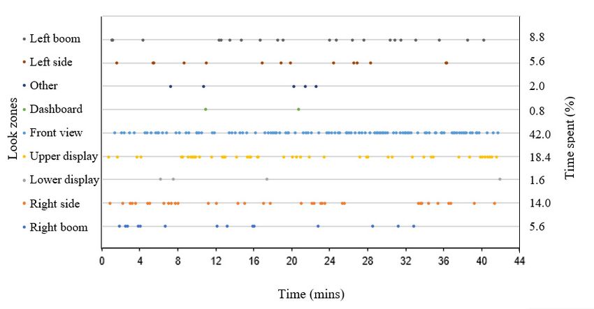
Appl. Sci. 2020, 10, 2794 3 of 16
Appl. Sci. 2020, 10, x FOR PEER REVIEW 3 of 16
of the information to the operation of the machine. Considering the cost and technical challenges
associated
challengeswith wirelesswith
associated transmission
wireless of live video and
transmission the video
of live risk of and
overcrowding
the risk ofthe interface with
overcrowding the
multiple
interfacevideo
withdisplays,
multipleit video
is essential to determine
displays, the visual
it is essential information
to determine thethat is typically
visual used by
information theis
that
machine
typicallyoperator
used by andthe
if the visual operator
machine information andcould bevisual
if the replaced with a graphical
information could display (consisting
be replaced with a
ofgraphical
icons or symbols) on the interface without impacting the perception of the information.
display (consisting of icons or symbols) on the interface without impacting the perception Therefore,
the
ofprimary objective Therefore,
the information. of the studythewas to determine
primary andof
objective evaluate
the study thewas
visual
to information
determine and thatevaluate
is gleaned the
from theinformation
visual machine and itsissurrounding
that gleaned fromenvironment
the machine thatand assists the operator
its surrounding with the control
environment of an
that assists the
agricultural machine.
operator with A secondary
the control objective was
of an agricultural to assess
machine. A whether
secondary visual information
objective was to present in live
assess whether
video
visualcould be replaced
information withina live
present graphical display
video could beconsisting
replaced withof icons or symbols
a graphical displayto represent
consistingvarious
of icons
machine parameters. Some examples of graphical displays in conventional
or symbols to represent various machine parameters. Some examples of graphical displays agricultural machines canin
beconventional
found in [13,14]; two examples
agricultural are shown
machines can be in Figure
found in1[13,14];
below. twoRecognizing
examplesthat arevisual
shown information
in Figure 1
requirements will be different
below. Recognizing for distinct
that visual agricultural
information machines,
requirements thebe
will self-propelled
different foragricultural sprayer
distinct agricultural
was selected for this study.
machines, the self-propelled agricultural sprayer was selected for this study.
Figure 1. 1.An
Figure Anexample
exampleofofa agraphical
graphicaldisplay
displayfor
fora asprayer (adapted
sprayer from
(adapted [13]).
from [13]).
2. Materials and Methods
2. Materials and Methods
2.1. Identification of Look Zones during Manual Sprayer Operation
2.1. Identification of Look Zones During Manual Sprayer Operation
Arrangements were made to observe the operator of a high clearance, self-propelled agricultural
Arrangements were made to observe the operator of a high clearance, self-propelled agricultural
sprayer (Rogator 1100 AGCO, Duluth, GA, USA) equipped with autosteer technology during the 2017
sprayer (Rogator 1100 AGCO, Duluth, GA, USA) equipped with autosteer technology during the
growing season. The participant who volunteered his sprayer and farmland for this phase of the
2017 growing season. The participant who volunteered his sprayer and farmland for this phase of the
study was a farm owner with 12 years of spraying experience who also performed custom spraying.
study was a farm owner with 12 years of spraying experience who also performed custom spraying.
One GoPro camera (GoPro, San Mateo, CA, USA), identified as camera M in Figure 2, was mounted
One GoPro camera (GoPro, San Mateo, CA, USA), identified as camera M in Figure 2, was mounted
on the windshield inside the sprayer’s cab to record the head and eye movement of the operator.
on the windshield inside the sprayer’s cab to record the head and eye movement of the operator. The
The video was recorded on the morning of 6 July 2017 on a flat field in Rosser, MB (137 acres in size),
video was recorded on the morning of 6 July 2017 on a flat field in Rosser, MB (137 acres in size), for
for approximately 42 min of spraying time (this was the time taken to cover the entire field). During
approximately 42 min of spraying time (this was the time taken to cover the entire field). During the
the spraying operation, the field boundaries were first sprayed in an anti-clockwise direction (to give
spraying operation, the field boundaries were first sprayed in an anti-clockwise direction (to give
room for the sprayer to turn easily without going outside the field), before straight parallel swaths
room for the sprayer to turn easily without going outside the field), before straight parallel swaths
were completed to traverse the remaining (unsprayed) area of the field. Subsequent analysis of the
were completed to traverse the remaining (unsprayed) area of the field. Subsequent analysis of the
video footage from camera M was performed to identify the various look zones from the operator’s
video footage from camera M was performed to identify the various look zones from the operator’s
perspective as described by [14]. One of the co-authors rode along with the sprayer operator to ask
perspective as described by [14]. One of the co-authors rode along with the sprayer operator to ask
questions (i) about the reasons for viewing the various look zones and (ii) the type of information
questions (i) about the reasons for viewing the various look zones and (ii) the type of information
being acquired when viewing the look zones. Although we asked questions during the actual spraying
being acquired when viewing the look zones. Although we asked questions during the actual
operation rather than interviewing the operator after data analysis had been completed as suggested
spraying operation rather than interviewing the operator after data analysis had been completed as
by [14], this is an important complementary component of the experimental methodology.
suggested by [14], this is an important complementary component of the experimental methodology.
To determine the amount of time the operator spent viewing each look zone, an algorithm for
converting video recordings to images was developed using Python 2.7.16 (Python Software
Corporation, Fredericksburg, VA, USA). The algorithm was used to convert the in-cab video
recordings to images, each corresponding to 10 s of the recorded video footage. These images were
then manually classified based on their look zones to measure the relative time the operator spent
observing each zone.recording was completed on the morning of 6 July 2017 on a flat field near Rosser, MB (137 acres in
size). Video duration was approximately 42 min (which was the time required to spray the entire
field). On a separate occasion (21 July 2017), video was recorded from a drone to provide an overhead
view of the entire sprayer. A third party licensed drone operator assisted in capturing the overhead
view on a field near Moosehorn, MB (120 acres in size); video was recorded for approximately 114min
Appl. Sci. 2020, 10, 2794 of 16
and covered only a portion of the spraying operation.
Figure 2.
Figure 2. A A schematic
schematicdrawing
drawingshowing
showingthe the various
various camera
camerapositions
positionson on the
the sprayer
sprayer during
during the
the first
first
phase of
phase of the
the project:
project: (a)
(a) plan
plan view;
view; (b)
(b) side
side view.
view. Cameras
Cameras were
were placed
placed onon each
each dot,
dot, while
while arrows
arrows
indicate the
indicate the direction
direction of
of the camera. Note: cameraPP==clip
Note: camera camera11 ==clip
clipP;P;camera camera22 ==clip
clip1;1;camera clip2.2.
Camera 55 was
Camera was mounted
mounted on on aa drone,
drone, while
while cameras
cameras 88 and
and 99 were
were third
third party
party hand-held
hand-held cameras
cameras that
that
were focused on the back of the sprayer and the field, respectively. Camera M was
were focused on the back of the sprayer and the field, respectively. Camera M was placed inside the placed inside the
sprayer’s cab to record the head and eye movement of
sprayer’s cab to record the head and eye movement of the operator.the operator.
To determine the amountTable 1.ofRationale
time theforoperator
choosing spent viewing
each camera each look zone, an algorithm
position.
for converting video recordings to images was developed using Python 2.7.16 (Python Software
Camera VA, USA). The algorithm
Corporation, Fredericksburg, Rationale
was used to convert the in-cab video recordings
Ability to observe the operator’s head and eye
to images, each corresponding to 10 s of the recorded video footage. These images were then manually
M movement (from his seated position) during the
classified based on their look zones to measure the relative time the operator spent observing each zone.
spraying operation.
To capture the field ahead of the sprayer and other
2.2. Determination of Relevant
1 Visual Information
environmental cues.
Nine GoPro cameras (Hero Session, with horizontal
To capture the view of the field
rightofand
viewleftof 120◦ and a video resolution
boom,
of 1920 × 1440) were mounted at respectively, as perceived
different locations on a from
highthe typical seated
clearance, self-propelled agricultural
P and 2
sprayer (Rogator 1100) to captureposition of an operator
video footage in theregions
of various cab of aof
self-propelled
the sprayer and its environment
while the sprayer was in operation (Figure 2). Various sprayer.
literature sources [14,15,17] were consulted
to position the GoPro cameras
3, 4, 6, 7, on the sprayer. Thearound
To capture regions rationalethe sprayer
for the that are
positioning of each camera is
currently not visible to operators (from their seated
provided in Table 1. 8,
Some
and 10cameras were positioned to provide familiar views (i.e., look zones that a
position).
sprayer operator would typically see from the seated position), while other cameras were positioned
To capture off-field (third party) views and assess
to provide non-traditional
5 and views
9 (i.e.,
theirlook zones that
usefulness to theare not visible
remote fromofthe
supervisor the seated position). Video
recording was completed on the morning of autonomous 6 July 2017 on a flat
sprayer(s).field near Rosser, MB (137 acres in
size). Video duration was approximately 42 min (which was the time required to spray the entire field).
On a separate occasion (21 July 2017), video was recorded from a drone to provide an overhead view
of the entire sprayer. A third party licensed drone operator assisted in capturing the overhead view
on a field near Moosehorn, MB (120 acres in size); video was recorded for approximately 11 min and
covered only a portion of the spraying operation.
Subsequent to collection of the video footage, clips of approximately 60 s in duration were selected
from the full video, which showed a large variation in the spraying operation, the sprayer’s operational
status, and the field or environmental conditions. Experienced sprayer operators (defined as having at
least two years of experience operating a sprayer) were recruited from the prairie provinces (Manitoba,
Saskatchewan, and Alberta) through industrial partners (Northstar Robotics), university, and farmers’
group contacts to participate in this phase of the research. Participants had the choice to either come in
person to the Agricultural Ergonomics Lab at the University of Manitoba to complete the experiment
or to complete the study online. All participants were required to give their consent prior to the
commencement of the experiment. After answering demographic questions, participants were required
to view a series of video clips and complete a questionnaire consisting of six questions. In total, elevenAppl. Sci. 2020, 10, 2794 5 of 16
video clips were presented to each participant: one practice clip (clip P) and ten test clips (clips 1–10).
The practice clip was included to allow participants to familiarize themselves with the experimental
protocol and the questions that followed each video. Video clips showing familiar views of the sprayer
and its environment (from the operator’s seated position) were presented before non-traditional views.
Table 1. Rationale for choosing each camera position.
Camera Rationale
Ability to observe the operator’s head and eye movement (from his
M
seated position) during the spraying operation.
1 To capture the field ahead of the sprayer and other environmental cues.
To capture the view of the right and left boom, respectively, as perceived
P and 2 from the typical seated position of an operator in the cab of a
self-propelled sprayer.
To capture regions around the sprayer that are currently not visible to
3, 4, 6, 7, 8, and 10
operators (from their seated position).
To capture off-field (third party) views and assess their usefulness to the
5 and 9
remote supervisor of the autonomous sprayer(s).
The video clip questionnaire comprised six questions. The first three questions were open-ended
and required participants to describe: (i) what they saw in each video clip, (ii) the information
gained from each video clip, and (iii) how they could use such information during operation of the
sprayer. The fourth question asked if the video clip was something the operator typically viewed when
operating a sprayer (yes/no response) and whether such a view is useful to the spraying operation
(yes/no response). Question 5 required the participant to rank the importance of the visual information
perceived using a 5-point Likert scale. In the final question, participants were asked to assess whether
the information would be best presented via live video or whether the information could be encoded
and incorporated into a graphical display for a sprayer. The video clip questionnaire was completed
after viewing each video clip.
3. Results and Discussion
3.1. Identification of Look Zones during Manual Sprayer Operation
Analysis of the in-cab video footage (camera M) revealed nine look zones: (i) the view ahead of the
operator from his seated position (i.e., front view); (ii) right side; (iii) right boom; (iv) left side; (v) left
boom; (vi) upper display/mapping system (located at the top right corner from the operator’s seated
position); (vii) a second display (located close to the right arm rest); (viii) sprayer’s dashboard/steering
wheel; and (ix) left mirror/other (Figure 3). The participant was also seen making adjustments to the
sprayer settings (through the displays) and checking his phone. Overall, he spent 39% of his time
looking at the front view (Figure 3). This finding is consistent with the results of [15], who noted
that sprayer operators spent the most time looking at the field ahead (i.e., front view), while the least
attention was given to the dashboard information. When asked why he was looking at these regions,
his reasons were (i) to determine how close the booms were to the field boundary, (ii) to assess if
the nozzles were working properly, and (iii) to ensure that there were no obstacles close to the field
boundaries and along the sprayer’s path that would require him to manually raise the boom. He also
stated that the front view helped him to determine when to take over the steering wheel to initiate
turning at the headland.Appl. Sci. 2020, 10, x FOR PEER REVIEW 6 of 16
Appl.
Appl. Sci. 2020, 10,
Sci. 2020, 10, 2794
x FOR PEER REVIEW 66 of
of 16
16
Front view
Front view
Upper display
Other
Upper display
Other
Left Side Right Side
Lower
Left Side Right Side
Dashboard display
Lower
Dashboard display
Left boom Right boom
Left boom Right boom
Figure 3. Look zones from the operator’s perspective during spraying operation.
Figure 3. Look zones from the operator’s perspective during spraying operation.
AnotherFigure
method3. Look zones from the
for interpreting operator’s perspective
eye-tracking during spraying
data is to represent operation.
the data as a function of time
Another method for interpreting eye-tracking data is to represent the data as a function of time
to give a sense of the cyclical nature of the task [14]. The data collected in this study are presented as
to give a sensemethod
Another of the cyclical nature ofeye-tracking
for interpreting the task [14]. The is data collected indata
this asstudy are presented
a function of time in Figure 4. The data show thatdata to represent
the operator the
was focused a function
primarily on fourof time
look
as
to a function
give a sense ofoftime
the in Figure
cyclical 4. The
nature of datatask
the show
[14].that
The the
data operator
collectedwasin focused
this study primarily
are on four
presented as
zones (front view, upper display, right side, and right boom) during the first 9 min of video footage—
look
athis zones
function (front
of time in view, upper display, right side, and right boom) during the first 9 min of video
corresponded toFigure
the time4. when
The data show
he was that thethe
spraying operator was focused
field boundary. Theprimarily
front view onenables
four lookthe
footage—this
zones (front corresponded
view, upper to the
display, time
right when
side, and he wasboom)
right spraying the the
during field boundary.
first 9 min of The front
video view
footage—
operator to assess where he is going and when to initiate turning, while the look zones to the right
enables
this the operator to assess where he is going and when to initiate turning, while the look zonestheto
(i.e.,corresponded
right side andtoright the time
boom) when
enable was spraying
the operator the
to field
guide boundary.
the sprayer Thealong front
the view
field’senables
boundary.
the right (i.e.,
operator to whenrightwhere
assess side and right
he is goingboom)
and enable
when tothe operator
initiate to guide thethe
sprayer alongtothe field’s
Therefore, the operator was spraying along the fieldturning,
boundary, while look zones
his attention was split the right
between
boundary.
(i.e., right Therefore,
side and rightwhen the enable
boom) operator the was spraying
operator to alongthe
guide thesprayer
field boundary,
along the his attention
field’s boundary.was
looking ahead and watching the right side of the sprayer. Once the field boundary was completed,
split between
Therefore, looking
whenviewing ahead
the operator and watching
wasboom
spraying the right
along the side of the sprayer. Once the field boundary
field boundary, his attention was split between was
the time spent the right decreased noticeably.
completed,
looking ahead the and
timewatching
spent viewing the right
the right side ofboom decreased
the sprayer. noticeably.
Once the field boundary was completed,
the time spent viewing the right boom decreased noticeably.
Figure 4. Video data represented as a function of time to demonstrate the monitoring behavior of the
Figure 4. Video data represented as a function of time to demonstrate the monitoring behavior of the
operator during spraying operation. Each dot represents 10 s of the recorded video. Additionally,
operator during spraying operation. Each dot represents 10 s of the recorded video. Additionally, the
the gap atVideo
Figure the beginning of the graph aindicates the time interval between when the GoPro cameraofwas
gap at 4.the data represented
beginning of the graphas indicates
functionthe
of time
time to demonstrate
interval between thewhen
monitoring behavior
the GoPro the
camera was
turned onduring
operator and when the spraying
spraying operation
operation. Each began.
dot represents 10 s of the recorded video. Additionally, the
turned on and when the spraying operation began.
gap at the beginning of the graph indicates the time interval between when the GoPro camera was
turned on and when the spraying operation began.Appl. Sci. 2020, 10, 2794 7 of 16
Appl. Sci. 2020, 10, x FOR PEER REVIEW 7 of 16
3.2.
3.2. Determination
DeterminationofofRelevant
RelevantVisual
VisualInformation
Information
3.2.1. Participant
3.2.1. ParticipantDemographics
Demographics
Twenty-nine experienced
Twenty-nine experienced male
malesprayer
sprayeroperators
operatorsparticipated
participatedininthis
thisphase
phaseofofthe
theresearch,
research, 73%
73%of
which
of whichwere fromfrom
were Manitoba, 17% from
Manitoba, 17% Saskatchewan,
from Saskatchewan,and 10% from
and 10%Alberta. Among these
from Alberta. Among 29 operators,
these 29
26 of them26
operators, completed
of them the study online,
completed whileonline,
the study the remaining
while theoperators
remainingcompleted
operators thecompleted
experimentthe in
person. Approximately
experiment 50% of the respondents
in person. Approximately 50% of thewere within the were
respondents age bracket
withinofthe41–65
age and self-reported
bracket of 41–65
to have
and more than 6toyears
self-reported haveofmore
experience
than 6operating
years ofa experience
sprayer. Almost 30% ofarespondents
operating sprayer. Almostwere between
30% of
the ages of 16
respondents andbetween
were 25, withthe
two-thirds
ages of 16 of and
these25,
individuals havingofless
with two-thirds than
these 2 years ofhaving
individuals experience
less
operating
than a sprayer
2 years (Figureoperating
of experience 5). Two of the participants
a sprayer reported
(Figure 5). Two ofthatthethey had not operated
participants a sprayer
reported that they
within
had notthe 12-month
operated periodwithin
a sprayer prior tothe
participating in thisprior
12-month period study.toOnly 10% of respondents
participating in this study.were
Onlycustom
10%
applicators,
of respondents with the custom
were remaining respondents
applicators, withbeing farm owners
the remaining (and therefore
respondents beingspraying
farm ownersonly (and
their
own crops).
therefore Self-propelled
spraying sprayers
only their ownwere operated
crops). by 88% of respondents,
Self-propelled sprayers were with the remainder
operated by 88% of the
of
respondents using pull-type sprayers. All but one participant used auto-steer navigation
respondents, with the remainder of the respondents using pull-type sprayers. All but one participant technology
whenauto-steer
used spraying.navigation technology when spraying.
45 41
Responses (%)
2-5
30 6 - 15
21
> 15
15 10
7 10 7
3
0 0 0 0 0 0 0 0
0
16 - 25 26 - 30 31 - 40 41 - 65 > 65
Age Range
Groupingof
Figure5.5.Grouping
Figure ofparticipants
participantsby
byage
ageand
andwith
withrespect
respectto
totheir
theiryears
years of
of experience
experience in
in spraying.
spraying.
3.2.2. Preliminary Observations from the Practice Clip
3.2.2. Preliminary Observations from the Practice Clip
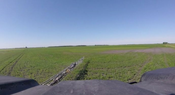
A screen shot from the practice video clip (clip P) is shown in Figure 6. Participants described the
A screen shot from the practice video clip (clip P) is shown in Figure 6. Participants described
practice video clip as the left boom of a sprayer applying chemicals on the field (based on mist present
the practice video clip as the left boom of a sprayer applying chemicals on the field (based on mist
in the video). Specific features that were seen included the spray pattern, properly functioning nozzles,
present in the video). Specific features that were seen included the spray pattern, properly
stable but relatively low boom height, no visible obstacles in the field, and the presence of green
functioning nozzles, stable but relatively low boom height, no visible obstacles in the field, and the
crop (short in height). Participants also noticed that the field was level, had previously been sprayed
presence of green crop (short in height). Participants also noticed that the field was level, had
(given the wheel tracks), and had several regions where no crop was growing. Most participants
previously been sprayed (given the wheel tracks), and had several regions where no crop was
identified boom features (left boom height, nozzle, and spray pattern) and crop (or field) conditions as
growing. Most participants identified boom features (left boom height, nozzle, and spray pattern)
the information that was gained from watching the practice clip. A majority (86%) of the participants
and crop (or field) conditions as the information that was gained from watching the practice clip. A
indicated that the information provided by the practice clip was something they typically viewed
majority (86%) of the participants indicated that the information provided by the practice clip was
while spraying. Among the 14% of participants who did not indicate that such information was
something they typically viewed while spraying. Among the 14% of participants who did not indicate
typically viewed during spraying, 50% of them felt that it would useful to see the areas provided
that such information was typically viewed during spraying, 50% of them felt that it would useful to
by the practice clip. When asked how they would use the information gained from the practice clip,
see the areas provided by the practice clip. When asked how they would use the information gained
participants indicated that the information would help them to identify if nozzles were plugged, to set
from the practice clip, participants indicated that the information would help them to identify if
their guidance line to match the previous passes or tracks (since the field had previously been sprayed),
nozzles were plugged, to set their guidance line to match the previous passes or tracks (since the field
to determine the type of spraying method that would be economical (i.e., adopting full application or
had previously been sprayed), to determine the type of spraying method that would be economical
spot spraying), and to make navigation decisions (e.g., deciding whether to go into low areas of the
(i.e., adopting full application or spot spraying), and to make navigation decisions (e.g., deciding
field, considering the risk of getting stuck). Two participants also noted that the information would
whether to go into low areas of the field, considering the risk of getting stuck). Two participants also
give an operator the assurance that they were doing a good job. In response to the fifth question, 86%
noted that the information would give an operator the assurance that they were doing a good job. In
of the participants indicated that the information provided by the practice clip was “very important”
response to the fifth question, 86% of the participants indicated that the information provided by the
or “extremely important”. Almost two-thirds of the participants (62%) indicated that it would be
practice clip was “very important” or “extremely important”. Almost two-thirds of the participants
difficult to gain the same information if the live video was replaced with an encoded display. Overall,
(62%) indicated that it would be difficult to gain the same information if the live video was replaced
with an encoded display. Overall, analysis of the data from the practice clip gave us confidence thatAppl. Sci. 2020, 10, 2794 8 of 16
Appl. Sci. 2020, 10, x FOR PEER REVIEW 8 of 16
Appl. Sci. 2020, 10, x FOR PEER REVIEW 8 of 16
participants
analysis of theaccurately understood
data from the thegave
practice clip purpose of the that
us confidence research and the
participants questions
accurately in the
understood
participants accurately understood the purpose of the research and the questions in the
questionnaire.
the purpose of the research and the questions in the questionnaire.
questionnaire.
Figure 6. A screen shot of the practice video clip (clip P).
Figure 6. A screen shot of the practice video clip (clip P).
3.2.3. Information
Information Gained from Test
3.2.3. Information Gained from Test Clips
Clips
Screen shots from the ten clips used in this study
study are shown
shown in Figure
Figure 7. Participant responses
Screen shots from the ten clips used in this study are are shown in in Figure 7.7. Participant responses
regarding the information gained from each video clip and how that information information could
could bebe used
used (i.e.,
(i.e.,
regarding the information gained from each video clip and how that information could be used (i.e.,
two of the
the open-ended
open-endedquestions
questionsfrom
fromthe
thequestionnaire)
questionnaire)are are tabulated
tabulated in
in in the
thethe appendix.
Appendix A
A. A summary
A summary
summary
two of the open-ended questions from the questionnaire) are tabulated appendix.
of the responses
responses to
to questions
questions4–6
4–6isisprovided
providedininTable
Table2,2,with
with full
full details
details provided
provided in in
thethe appendix.
Appendix A.
of the responses to questions 4–6 is provided in Table 2, with full details provided in the appendix.
Only two of the video clips (1 and 2) were typically viewed by a majority of the participants when
Only two of the video clips (1 and 2) were typically viewed by a majority of the participants when
operating their sprayers (Table 2). Not Not surprisingly,
surprisingly, these
these were
were the only two video clips where a
operating their sprayers (Table 2). Not surprisingly, these were the only two video clips where a
majority of participants identified the level of importance of the information provided to be “very
majority of participants identified the level of importance of the information provided to be “very
important” or “extremely important”. Video Video clips
clips 333 through
through 77 were not perceived to
important” or “extremely important”. Video clips through were not perceived to provide
provide visual
visual
information that is relevant to the task of operating
operating an an agricultural
agricultural sprayer.
sprayer.
information that is relevant to the task of operating an agricultural sprayer.
Figure 7. Screen shots from clips 1–10.
Figure 7. Screen shots from clips 1–10.
The utility
Table of the information
2. Summary provided
of responses from in the video
experienced clips
sprayer is more
operators (ndifficult
= 29) whotocompleted
summarize. Generally,
the video
Table 2. Summary of responses from experienced sprayer operators (n = 29) who completed the video
participants used the
clip questionnaire. video clips to obtain information about the boom status, the location and
clip questionnaire.
movement of the sprayer within the field, the weather conditions (especially the wind), obstacles
Participant Preference for Visual Information
toVideo
be avoided, crop conditions,
Typically and
High field
Level of conditions.Participant
However,Preference
not allfor Visual
video Information
clips were equally
Video Typically High Level of Live Graphical No Substantial
Clip
effective Viewed (%) Importance * (%) Live Graphical No Substantial
Clip at Viewed
providing(%) information for these
Importance * (%) relevant parameters. Participants were able to gather
Video (%) Display (%) Impact (%)
information regarding the field conditions and Video
travel (%) of the
speed Display
sprayer(%)from almost Impact
all24of(%)
the clips.
1 97 79 55 21
1 97
This2 outcome is93not surprising given 79 that the field 55
was present in21
all the video clips 24 all clips
and
83 62 17 21
2 93 83 62 17 21
featured
3 some aspect
10 of the sprayer 18 against the stationary
21 background 10 of the field. It should
69 be noted,
3 10 18 21 10 69
however,
4 that information
3 about many
14 of the other parameters
41 was10 available in only a subset
48 of the
4 3 14 41 10 48
5 7 10 28 21 48
5 7 10 28 21 48
6 0 10 28 7 66
6 0 10 28 7 66Appl. Sci. 2020, 10, 2794 9 of 16
clips. Information about boom height, leaks, crop condition, wheel alignment with previous tracks,
machine integrity, weather (wind), and obstacles could be determined from five to seven video clips.
Information about the sprayer’s location, spray pattern, nozzle status (not plugged), spray drift, and
how close the boom end was from the field boundary could be determined from only three or four
video clips. Features such as sprayer clearance, section control, boom stability, turning at headland,
size of the field, object behind the sprayer, field boundary, side of the sprayer, and knowing that the
sprayer was in the right field could be determined from only one or two clips. Participants’ ability
to identify any useful visual information from the sprayer and its surrounding environment was not
dependent on how frequently such information was presented. As an example, 28% of participants
considered “turning at headland” to be valuable, even though it was only presented in one of the clips
(as perceived by participants), while fewer participants identified the “approximate travel speed” as
visually important, even though it was perceived in all the video clips (see Appendix A).
Table 2. Summary of responses from experienced sprayer operators (n = 29) who completed the video
clip questionnaire.
High Level of Participant Preference for Visual Information
Typically
Video Clip
Viewed (%) Importance * (%) Graphical No Substantial
Live Video (%)
Display (%) Impact (%)
1 97 79 55 21 24
2 93 83 62 17 21
3 10 18 21 10 69
4 3 14 41 10 48
5 7 10 28 21 48
6 0 10 28 7 66
7 28 3 34 0 59
8 10 41 24 31 41
9 3 31 52 14 31
10 14 31 41 3 52
* Proportion of participants who rated the level of importance as either “very important” or “extremely important”
to the operation of the sprayer.
Furthermore, environmental cues were considered important by participants when such cues
were presented in relation to the spraying operation. For example, a higher number of participants
perceived the field boundary to be valuable information when the end of the boom was visible with
respect to the field boundary. However, fewer participants perceived the “field boundary” to be useful
in clips that didn’t relate it to the spraying operation (boom), despite being visible. In other words,
the field boundary is only important with respect to the position of the sprayer—the user does not care
about the location of the field boundary unless it is presented in relation to the position of the boom.
A summary of the information gained by operators based their look zones is presented in Figure 8.Appl.
Appl. Sci. 2020, 10,
Sci. 2020, 10, 2794
x FOR PEER REVIEW 10
10 of
of 16
16
Field boundary, obstacle,
weather- wind, field/crop
condition (42.0%).
Coverage map,
skip/overlap, GPS
Field/crop application rate,
condition, boom/nozzle status
mirror—left boom (18.4%)
(2.0%)
Field/crop Field/crop
conditions and conditions,
obstacles Sprayer setting, field
(5.6%) progress, and boundaries,
notifications and obstacles
(1.6%) (14.0%)
Machine speed and
integrity (0.8%)
Boom/nozzle condition, spray
Boom/nozzle condition, spray drift, distance between boom
drift and distance (8.8%) and field boundary (5.6%)
Figure 8. Information gained based on from the operator’s look zone during spraying operation.
Figure 8. Information gained based on from the operator’s look zone during spraying operation.
3.2.4. Effect of Operators’ Experience on Information Gained
3.2.4. Effect of Operators’ Experience on Information Gained
The years of operating experience of the participants did not influence their responses towards
Theof
the level years of operating
importance experience
of each video clipof
orthe participants
with did not influence
respect to replacing their aresponses
the clips with graphicaltowards
display;
the level itofdid
however, importance
influence of
theeach videotoclip
responses theor with respect
open-ended to replacing
questions the clips with Participants
in the questionnaire. a graphical
display;
with however, or
intermediate it did influence
extensive the responses
experience operatingto the open-ended
a sprayer questions
were able in the more
to articulate questionnaire.
useful or
Participants
relevant with intermediate
information or extensive
from the video clips thanexperience
their peersoperating
with less aoperating
sprayer experience
were able to articulate
(Table 3).
more useful or relevant information from the video clips than their peers with less operating
3). 3. Information gained as a function of a participant’s experience.
experience (Table Table
Clip General Description < 5 Years Experience 5–15 Years Experience >15 Years Experience
Table 3. Information gained as a function of a participant’s experience.
Front view from
1 Turning, speed, track path Turning, track path, windy. Turning, windy, obstacle.
sprayer
Generalcabin.
Clip < 5 Years Experience 5–15 Years Experience >15 Years Experience
Description Sprayer is operating, crop
Nozzle status, boom
2 FrontRight
viewboom
from Nozzle status,
Turning, speed, track Turning, track from
height, distance path,field condition, boom height,
Turning, windy,
1 spraying chemical. boom height.
boundary, spray pattern.
obstacles, travel speed,
sprayer cabin. path windy. obstacle.
distance from field edge.
Topography, leaks,
Sprayer is operating,
Boom is still attached,
Leak, how deep you can Nozzle status, boom
3 Left side of sprayer. teaching moment, machine croptravel
condition, boom
speed, boom
Right boom Nozzle status,
sink, very boom
little. height, distance from
2 integrity, not much. height, obstacles,
stability, not much.
spraying chemical. height. field boundary, spray
travel
Cropspeed, distance
conditions, leaks,
Fieldpattern.
condition, leaks,
Leaks, crop respond, crop height,
from fieldcrop damage,
edge.
4 Underneath of sprayer. machine integrity,
crop height. travel speed, clearance,
Topography, leaks,
not much.
Boomnothing
is still attached,
much.
Left side of Leak, how deep you teaching moment,
3 travel speed,
Weather, sprayerboom
is in the
sprayer.
Distance sprayer can sink,
Field very little.
variability, size of machine integrity,
Wind condition, not of
amount
desired field, windy,
5 working in a field, boom height, drift, much.
sprayer location, stability, not much.
sprayer is still moving,
windy field. not much. not much.
Cropnot much.
conditions,
Field condition, leaks, leaks, cropconditions,
Leaks, field height,
Underneath of
View of spray/rinse
Leaks,
Tankcrop respond,
is full, sprayer is
Machine integrity, sprayer is operating,
64 sprayer. driving
crop straight,
height.
machine integrity, not crop damage, travel
tank and field. weather, nothing. making turns,
nothing much. much. speed, clearance,
obstacles, nothing.
nothing much.
Travel speed, crop
Left side sprayer
of sprayer Side view of
Weather, sprayer is in
7 Distance Field variability, size WindBeneficial for off-field
condition, amount condition, weather, field
showing crop. sprayer, nothing. operation, nothing. the desired field,
conditions,
5 working in a of field, boom height, of drift, sprayer location,
obstacles,
windy, sprayernothing.
is still
windy field. not much. not much.
moving, not much.
View of Tank is full, sprayer Leaks, field
Machine integrity,
6 spray/rinse tank is driving straight, conditions, sprayer is
weather, nothing.
and field. nothing much. operating, makingAppl. Sci. 2020, 10, 2794 11 of 16
Table 3. Cont.
Clip General Description < 5 Years Experience 5–15 Years Experience >15 Years Experience
Sprayer is operating, field
Nozzle status, spray
Back of sprayer and weather conditions,
8 Nozzle status, nothing. pattern, boom height,
driving up a field. nozzle status, wind, travel
spray drift, leaks, nothing.
speed, spray drift.
Sprayer is operating,
Field conditions, sprayer’s Distance of boom from
Aerial (drone) view of following field edge,
location, sprayer is field boundary, field
9 sprayer operating in a obstacles, field conditions,
applying chemical condition, sprayer’s
canola field. location of sprayer, boom
within boundary. location, obstacles.
is fully open, travel speed.
Spray drift, travel speed, Spray drift, weather, spray
Field behind the field condition, crop pattern, travel speed, track
Spray drift, crop damage
10 sprayer while it condition, staying on track, alignment with previous
due to tire.
is moving. wheel alignment, path, front and rear
not much. wheel alignment.
3.2.5. Influence of Camera Position
The experimental data were analyzed to determine the effect of the camera position on the visual
information gained. When specific features of either the sprayer or its environment were prominently
displayed within the frame of the camera, participants were more likely to comment on the information
gained from that specific feature than information that could be gained from other less prominent
features. For example, clip 2 focused mainly on the “right boom” and many participants identified
features that were related to the boom as being valuable. Similarly, clip 9 emphasized the field and
most participants focused on the relevant information that was gained from the field. This finding
suggests that designers can influence which features the user will perceive by positioning the camera
such that those specific features are prominent in the camera’s field of view.
3.2.6. Alternate Camera Placement
Other views that were suggested included a camera at the end of the boom facing forward (24%),
a close-up view of the nozzle and its tip (24%), a view from under the sprayer facing backward to see
the spray pattern behind the sprayer and wheels (10%), dashboards or displays (10%), and a camera
that would focus on the wheel to show how well an operator was either following old tire tracks or
steering within the rows of a corn crop (7%).
3.2.7. Live Video or Graphical Display of Information
A majority of participants indicated a preference for retaining important visual information in the
format of live video on a hypothetical automation interface for remotely supervising an autonomous
agricultural machine. For clips 1 and 2 (perceived to display the most important information),
participants noted that it would be difficult to perceive the same information if they were replaced with
graphical displays. However, they indicated that replacing clips 3, 5, 6, and 7 with a graphical display
would not have any substantial impact on their ability to operate the sprayer. This divergent result
may be due to the fact that most participants did not perceive any valuable information from the latter
set of clips. Observed results from several of the other clips (i.e., clips 4, 8, 9, and 10) is more difficult to
interpret. In-depth analysis revealed that the participant’s response to this question was related to
the information perceived from the clip. For example, in clip 8, some participants identified relevant
information such as spray drift, spray pattern, and backing up; these aspects of sprayer operation
might be difficult to portray on a graphical display, perhaps leading these participants to prefer live
video. For the same video clip, other participants reported no substantial impact when replacing
live video with a graphical display. These participants identified features such as wheel alignment
or following a previous wheel track—features that could perhaps be displayed more easily using a
graphical display. Overall, experienced sprayer operators reported higher preference for presentingAppl. Sci. 2020, 10, 2794 12 of 16
visual information on an automation interface using live video than presenting that same information
using some type of graphical display.
4. Conclusions
Having video footage of the sprayer and its environment during spraying operation is important
to the remote supervisor of an autonomous sprayer. Typically, experienced sprayer operators preferred:
(i) the view ahead of the sprayer (from the operator’s seated position), (ii) a view of the boom and
nozzles, and (iii) an aerial view of the sprayer in operation. The information that was perceived from
these views included the right boom, nozzle status (plugged or not), spray pattern, obstacles in front
or beside, poor areas in the field, wet spots, approximate travel speed, headlands, type of crop being
sprayed, weather (windy and sunny), application rate, boom height, location of the sprayer, overall
picture of the field (i.e., aerial view), and if the sprayer was moving and following the right path
(moving straight). With this information, operators felt that they would be able to identify consistency
in product application, changing elevation, and the upcoming field (e.g., headland). Experienced
operators believed that this information could be used to determine if they needed to stop and clean
a plugged nozzle, raise or lower a boom, continue spraying or stop spraying (in windy conditions),
increase or reduce speed and droplet size, decide where to spray or where not to (if no automatic section
control), when to adjust the wheel to stay on track or make turns, avoid spraying a neighbor’s field,
avoid obstacles, avoid wet spots, and as tools for teaching and training a novice operator. The level of
importance of the video clip increased with familiarity and how directly related the information is
to the operation of a sprayer. Overall, visual information of highly important or preferred parts of
the sprayer and its environment (as determined by experienced operators) should be retained in the
format of live video rather than encoding the information as part of a graphical display.
Author Contributions: Conceptualization, U.E. and D.M.; methodology, U.E. and D.M.; formal analysis, U.E.;
investigation, U.E.; writing—original draft preparation, U.E.; writing—review and editing, D.M.; visualization,
U.E.; supervision, D.M.; project administration, D.M.; funding acquisition, D.M. All authors have read and agreed
to the published version of the manuscript.
Funding: This research was funded by the Natural Sciences and Engineering Research Council of Canada, grant
number RGPIN-2018-05350.
Acknowledgments: The authors would like to acknowledge technical assistance from three summer students (E.
Hawley, G. Dyck, and F. Ogidi).
Conflicts of Interest: The authors declare no conflict of interest.Appl. Sci. 2020, 10, 2794 13 of 16
Appendix A
Table A1. A summary of participants’ responses to each video clip.
Information Gained (Multiple How Information Gained Can Be Used Typically Usefulness to “No” Replacing Clip
Video Clip Clip Description LoI Ranking; %
Responses Allowed; %) (Multiple Responses Allowed) Viewed; % Participants; % with Display
1 Front view from sprayer Too windy to be spraying—48 - Increase droplet size. Yes: 97 Yes: 0 L1 = 7 a = 55
cabin (operator’s sitting Staying on track—28 - Lower the boom. No: 3 No: 100 L2 = 0 b = 21
position). Turning at headland—28 - Avoid obstacle. n=1 L3 = 14 c = 24
Field condition—17 - Control speed at headland. L4 = 24
Approximate travel speed—10 - Prevent overlap/miss. L5 = 55
Obstacle—10 - Utilize old track.
Crop condition—3
No comment—10
2 Right boom spraying No plugged nozzle—38 - Clean plug nozzles. Yes: 93 Yes: 100 L1 = 3 a = 62
chemical. Boom height—28 - Set/control boom height. No: 7 No: 0 L2 = 3 b = 17
Section control—21 - Turn off boom. n=2 L3 = 10 c = 21
How close is the boom end to the field - Avoid obstacle. L4 = 28
boundary—21 - Avoid spraying another field. L5 = 55
Spray pattern—17
Crop condition—10
Obstacle—10
Approximate travel speed—10
Boom stability—3
Sharp turning—3
No comment—3
3 Left side of sprayer. No information gained—48 - Not useful Yes: 10 Yes: 23 L1 = 54 a = 21
Machine integrity—10 - Stop if a leak was identified. No: 90 No: 65 L2 = 14 b = 10
Travel speed—10 - Changing travel speed. Blank: 12 L3 = 14 c = 69
Sprayer clearance—7 n = 26 L4 = 14
No leaks—7 L5 = 4
Boom height—7
Sprayer response to field topography—7
Boom is still attached—3
Crop condition—3
Boom stability—3
Field condition—3
No comment—7
4 Underside of sprayer. No leaks—31 - Keep straight Yes: 3 Yes: 32 L1 = 31 a = 41
No information gained—24 - Stop if there was a leak. No: 97 No: 64 L2 = 34 b = 10
Sprayer clearance—17 - Keep your wheels in the existing Blank: 4 L3 = 21 c = 48
Machine integrity—17 sprayer tracks n = 28 L4 = 7
Travel speed—10 - Not useful L5 = 7
Crop condition—10 - Adjust travel speed.
Wheel alignment with previous - How high to set your center boom
path/track—10
Crop respond to tire—7
Field condition—3
Sprayer is still moving—3You can also read