Modified double dumbbell shaped split ring resonator based negative permittivity metamaterial for satellite communications with high effective ...
←
→
Page content transcription
If your browser does not render page correctly, please read the page content below
www.nature.com/scientificreports
OPEN Modified double dumbbell‑shaped
split‑ring resonator‑based negative
permittivity metamaterial
for satellite communications
with high effective medium ratio
Md Bellal Hossain1,2, Mohammad Rashed Iqbal Faruque1*, Sikder Sunbeam Islam3 &
Mohammad Tariqul Islam4
Metamaterial with negative permittivity demonstrate excellent performance in cutting-edge
technology. Thus, this study modified the double dumbbell-shaped split-ring resonator (MDD-SRR)
based negative permittivity for satellite communications. The proposed MDD-SRR unit cell comprises
a square-shaped split-ring resonator and two dumbbell-shaped rings. Some parts of the outer square
ring were extended to enlarge the electrical length which altered the inductance of the metamaterial
unit cell. The dimension of the proposed unit cell is 9 × 9 × 1.524 mm3, fabricated on a Rogers RT6002
(lossy) substrate material. Based on the results, five resonances for the transmission coefficient were
achieved at frequencies of 2.896 GHz, 8.11 GHz, 9.76 GHz, 12.48 GHz and 13.49 GHz, including the
S, X and Ku band satellite communication frequency bands through numerical simulation in a high-
frequency electromagnetic simulator Computer Simulation Technology (CST) microwave studio.
Negative permittivity at frequencies ranging from 2.896–3.76 GHz, 8.11–8.592 GHz, 9.76–10.784 GHz,
12.496–12.768 GHz, 13.504–14.4 GHz, were observed and extracted using the Robust and Nicolson–
Ross–Weir (NRW) methods. Meanwhile, an effective medium ratio (EMR) measured at 11.51 to
2.896 GHz specified the goodness of the metamaterial unit cell for satellite communication with
higher bandwidth and gain. The simulated, circuit model and measured results that were compared
for validation purposes indicated that the simulation results, the equivalent circuit model results and
measured results occupied each other. Moreover, the numerical simulation of the double dumbbell-
shaped metamaterial unit cell was performed using a High-Frequency Structure Simulator (HFSS)
to confirm the results. To evaluate the parametric study, the proposed unit cell was subjected to
change different substrate types, change of split gap of rings, change of direction of electromagnetic
field propagation, and structural optimization. In conclusion, the S, X and Ku-bands in the proposed
metamaterial are competent for satellite communications as they are also investigated using an array
of a unit cell.
In the year 1968, Victor V esselago1 introduced the idea of a non-existent material, where it has a negative per-
mittivity (ε) and permeability (µ) in a certain frequency span. However, no one expected this idea to become a
state of the art technology until 1999. In 2000, Smith et al.2 described the double negative material referred to
as left-handed metamaterial indicating negative effective medium parameters. Metamaterials can be incorpo-
rated into a vast array of applications due to their exotic electromagnetic properties. The applications include
bandwidth enhancement3,4, biomedical a pplications5, superlenses6, invisibility cloaks7, specific absorption rate
(SAR) reduction8,9, obstacle sensing10, chemical detection11, electromagnetic absorber12–14, energy harvesting15,16,
1
Space Science Centre (ANGKASA), Institute of Climate Change (IPI), Universiti Kebangsaan Malaysia, 43600
UKM Bangi, Selangor D.E., Malaysia. 2Department of Electrical and Electronic Engineering, Noakhali Science and
Technology University, Noakhali, Bangladesh. 3Department of Electrical and Electronic Engineering, International
Islamic University Chittagong, Chittagong, Bangladesh. 4Department of Electrical, Electronic and Systems
Engineering, Universiti Kebangsaan Malaysia, 43600 UKM Bangi, Selangor D.E., Malaysia. *email: rashed@
ukm.edu.my
Scientific Reports | (2021) 11:19331 | https://doi.org/10.1038/s41598-021-98703-4 1
Vol.:(0123456789)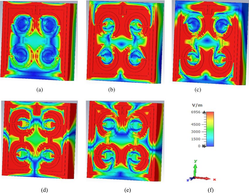
www.nature.com/scientificreports/
wavefront manipulation17,18, polarisation conversion19, vortex beam g enerators20,21 etc. Having said that, ordinary
materials are not relevant for these applications, where only metamaterials can be utilised due to their peculiar
properties. Ordinary materials only generate positive permittivity and permeability which are commonly found
in nature called a double positive media (DPS). However, some materials found in nature do exhibit negative
permittivity and permeability occasionally but not simultaneously are called a single negative media (SNG).
Meanwhile, metamaterials that generate negative ε and µ are not found in nature but are physically realisable
by incorporating geometrical shape structures on a dielectric substrate, called a double negative media (DNG).
Having said that, double negative and single negative metamaterials are both being applied for groundbreaking
discoveries. An earlier study demonstrated a man-made magnetic material based on an SRR, in which the SRR
was printed on a dielectric substrate with several shapes like as circular, rectangular, hexagonal, etc. Now, differ-
ent types of shapes such as the English alphabet, engineering and religious symbol, Greek letters and letter-like
symbols are used as a shape of SRR fabricated on dielectric medium.
Reference11 introduced a G-shaped resonator-based metamaterial absorber to detect various types of oils
and liquefied chemicals in the X-band region. A different type of metamaterial designed with an eSRR resonator
was proposed in Ref.10, where it was used for obstacle sensing in the C-band of the microwave region. Because
of the widespread applications in wireless communications, imaging and radar applications, the manipulation
of electromagnetic (EM) waves became highly desirable due to their effective control. Meanwhile, the proposed
wideband three-layered chiral structure metasurface can simultaneously combine polarisation and wavefront
of the transmitted w ave17. A novel concentric ring-based crossed line SNG metamaterial structure indicated by
Azeez et al.22 was fabricated on the most commonly used FR-4 dielectric substrate operating in Ku- and Ka-bands
with an EMR of 4.44. A. F. Almutairi et al.23 introduced a DNG metamaterial with 5.5 × 5.5 mm2 dimension,
which was validated using an 18 × 20 array structure. The DNG metamaterial was incorporated into C-band
microwave applications with an EMR value of 8. Another study presented an epsilon-negative metamaterial for
single-layer rectangular invisible cloaking activity that covers the C-band with low EMR24. While a separate study
proposed a hexagonal-shaped split ring resonator with a gap coupled for the microwave absorptance a pproach25.
This resonator was fabricated using an FR-4 dielectric substrate material covering C and X frequency bands
with a size of 10 × 10 mm2 at an EMR of 8.4. Whereas a modified circular electric resonator-based metamaterial
indicated a double negative characteristic, with a frequency band of 9.7–10.5 GHz and 15–15.7 GHz with an
EMR of 5.45 at 5 × 5 m m226. In another s tudy27, a horizontally inverted double L-shaped metamaterial was used
for microwave applications covering the C-, X- and Ku-bands with a dimension of 10 × 10 m m2. The results indi-
28
cated a double negative approach to the resonance frequencies. Meanwhile investigated the use of Jerusalem
cross-unit cell-based near-zero index (NZI) metamaterial to amplify the high antenna gain operating at 43 GHz.
Besides that, a new novel metamaterial presented in Ref.29 was manufactured on a Flame retardant-4 dielectric
substrate. The metamaterial displayed ENG properties in S-band, showing the DNG property whether Rogers
RT 6010 dielectric substrate is utilized. W hereas30 demonstrated a split-ring resonator-based metamaterial in the
form of a double H-shape to exhibit quadruple resonance for satellite applications. This metamaterial structure
yielded an EMR value of 10.75 at a size of 9 × 9 mm2. Moreover, Ramachandran et al.31 investigated a metamaterial
with a composite circular-shaped resonator with ENG properties for C-band and DNG characteristics for Ku-
band. In another s tudy32, a negative permittivity metamaterial based on a cross-coupled interlinked resonator was
implemented for satellite and radar approaches. This metamaterial unit cell was validated through the advanced
design system (ADS) software and was fabricated using different arrays. The unit cell size and EMR were 8 × 8
mm2 and 8.03, respectively. Additionally, a polarisation-dependent tunnelled metamaterial unit cell was proposed
to improve the field c haracteristics33. The EMR of this proposed metamaterial was 3.39 with a dimension of 10 × 8
mm2. On the other hand, a Greek-key pattern-based multiband metamaterial was investigated for miniaturisation
which was also validated through the 10 × 10 array of the metamaterial unit cell using the free-space measure-
ment technique34. The numerical size of the pattern and EMR were 10 × 10 mm2 and 12.5, respectively. In Ref.35,
a metamaterial-based absorber was proposed covering frequency bands of 1.8 GHz, 2.45 GHz and 5.80 GHz for
microwave images. Thus, a metamaterial-based energy harvester was designed for satellite communication and
a global system for mobile communications at frequencies, 0.9, 1.37, 1.61 and 2.55 GHz36. A new M-band nested
U-ring resonator was proposed for the X- and Ku-bands37, in which the resonant frequency can be independently
managed by changing the arm length. In another s tudy38, the proposed DNG metamaterial with a compact square
shape ring was successfully developed for quintuple resonance frequencies to extend the C, X and Ku frequency
bands for satellite applications with good EMR.
The choice of substrate material is important for a metamaterial unit cell design because it affects the reso-
nance frequency and EM properties. Subsequent studies were organized on different types of substrate materials.
In 2018, a typical TD-shaped metamaterial unit cell based on the flexible NiAl2O4 substrate was designed for
triple-band applications39. This study utilised the frequency range of 4–18 GHz by numerically mapping the
metamaterial structure in CST and HFSS simulator. A new metamaterial unit cell was designed and analysed on a
variety of substrates such as FR-4, Rogers RT 6010, lossy polyimide and aluminium nitride substrate materials40.
The unit exhibited DNG properties for Rogers RT 6010 and lossy polyimide substrate materials, whereas the
other substrate materials demonstrated SNG properties. However, all resonant frequencies covered the S-band.
In this study, a modified double dumbbell-shaped split-ring resonator (MDD-SRR) based negative permit-
tivity metamaterial was developed using Rogers RT-6002 dielectric substrate material with quintuple resonance
frequencies and high EMR indicating S-, X- and Ku-bands for satellite communications. In satellite and radar
systems, the S-, X- and Ku-bands have excellent applications. Particularly, the S-band is used from 2 to 4 GHz
to design invisible cloaks in military applications, while X- and Ku-bands ranging from 8 to 12 GHz and 12 to
18 GHz, respectively, can be used for satellite communications. Moreover, various parameters for the proposed
metamaterial such as ε, µ and η were calculated using the Robust and Nicolson–Ross–Weir (NRW) techniques.
The behaviour of the electromagnetic field analysis is also examined. A circuit model similar to the proposed
Scientific Reports | (2021) 11:19331 | https://doi.org/10.1038/s41598-021-98703-4 2
Vol:.(1234567890)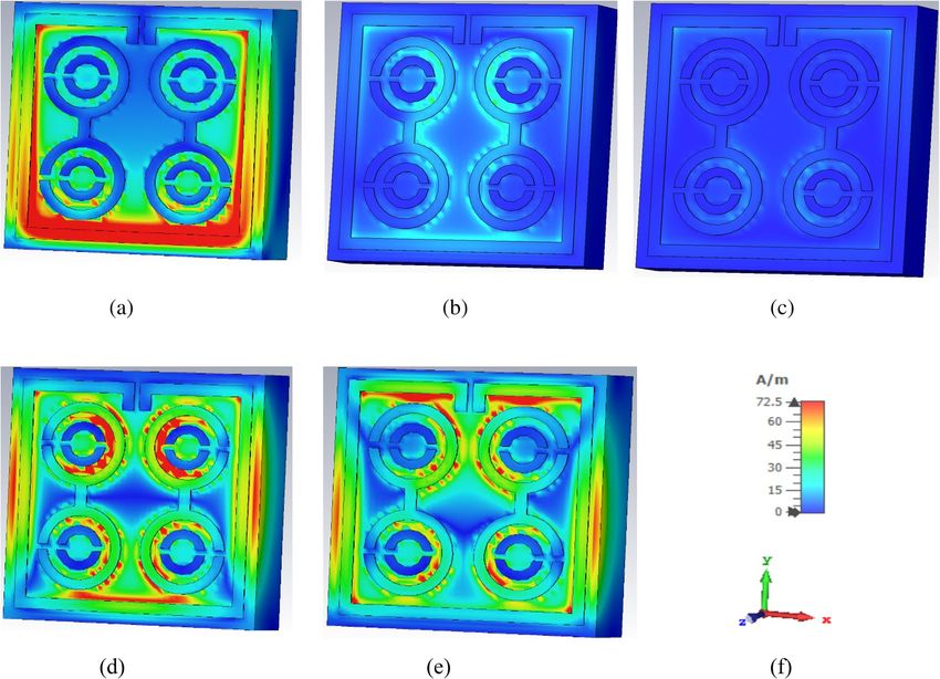
www.nature.com/scientificreports/

                                  Figure 1.  Perspective view of the proposed MDD-SRR unit cell.

                                   Parameter                                         Dimensions
                                   Thickness of the outer square ring, R             0.4 mm
                                   Thickness of the outer circular ring, O           0.35 mm
                                   Thickness of the inner circular ring, I           0.3 mm
                                   Length and Width of the substrate, L, W           9 mm
                                   Width of connector, C                             0.4 mm
                                   The gap between the whole strip, S                0.2 mm
                                   Length of extended part of outer square ring, E   0.6 mm

                                  Table 1.  The specification parameters of the proposed MDD-SRR unit cell structure.

                                  metamaterial unit cell was also outlined and the optimised values of the lumped components were calculated
                                  using the ADS software. The high EMR value assessed the goodness of fit of the metamaterial unit cell. Different
                                  array types, including 1 × 2, 2 × 2 and 8 × 8 arrays is also analysed. The S-parameter results of the unit cell were
                                  simulated using the HFSS. Finally, the modified double dumbbell-shaped split-ring resonator-based metamate-
                                  rial is fabricated and measured to validate the simulation results, which is suitable for satellite applications. The
                                  proposed unit cell and 1 × 2 array structure were fabricated and measured using Agilent N5227 PNA Microwave
                                  Network Analyzer showing an excellent agreement with the simulated results.

                                  Unit cell design. The proposed MDD-SRR was built on the Rogers RT6002 substrate as presented in Fig. 1.
                                  The proposed MDD-SRR unit cell structure contains four concentric circular metallic rings forming a dumbbell
                                  shape, etched on the Rogers dielectric substrate. Rogers RT6002 dielectric materials play an important role in
                                  the performance and electrical properties including low dielectric and electrical signal loss, low outgassing for
                                  satellite communication, etc. The dumbbell shape was formed by two interconnected double SRRs with 0.2 mm
                                  splits at opposite ends has two splits in the inner ring. Meanwhile, some parts of the outer square split ring were
                                  extended to expand the electrical length. The dielectric constant of the Rogers RT6002 substrate material was
                                  2.94, where the loss tangent was 0.0012. Having said that, the thickness of the substrate and copper metallic
                                  structure was 1.524 mm and 0.035 mm, respectively. The whole split gap of the proposed unit cell was 0.2 mm
                                  based on the trial and error to maintain uniformity that offers a maximum number of resonances with excellent
                                  EMR. Whereby, the CST simulator was used to perform numerical simulations of the unit cell. Table 1 illustrates
                                  all the split gap dimensions, metal length along with the inner and outer ring radius.

                                  Effective medium parameters extraction method. To extract effective valid parameters, we employed
                                  a Finite Integration Technique (FIT)-based high-frequency electromagnetic simulator CST microwave studio
                                  that was operated in a frequency range of 2–18 GHz using a hexahedral mesh. The transverse electromagnetic
                                  (TEM) wave propagating along the Z-axis through the proposed metamaterial unit cell and array structure was
                                  used to demonstrate the interaction between the fields. As depicted in Fig. 2, the electric field moves along the
                                  X-axis, whereas the magnetic field acts on the Y-axis. Whereas, the effective parameters were extracted using the

Scientific Reports |   (2021) 11:19331 |                     https://doi.org/10.1038/s41598-021-98703-4                                              3

                                                                                                                                                Vol.:(0123456789)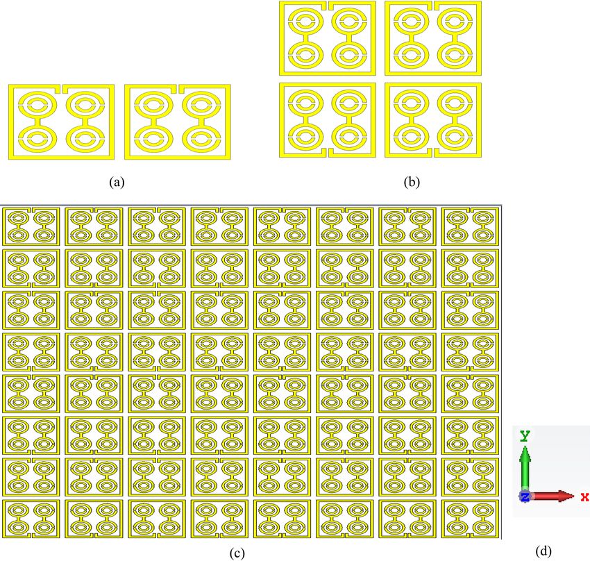
www.nature.com/scientificreports/
Figure 2. Simulation arrangement of proposed MDD-SRR structure.
Robust method41. Meanwhile, the relationship between the impedance, refractive index, reflection coefficient
(|S11|) and transmission coefficient (|S21|) were expressed using the following equations:
R01 (1 − ei2nk0 d )
|S11 | = , (1)
1 − R2 01 ei2nk0 d
(1 − R2 01 )ei2nk0 d
|S21 | = , (2)
1 − R2 01 ei2nk0 d
where R01 = z−1
z+1
By inverting Eqs. (1) and (2), the impedance z can be obtained by
(1 + S11 )2 − (S21 )2
Impedancez = ± . (3)
(1 − S11 )2 − (S21 )2
√
eink0 d = X ± i 1 − X 2 , where X = 2S (1−S1 2 +S2 ) .
21 11 21
The refractive index can be determined by the value of eink0 d,
1
"
′
Refractiveindex, n = [ln(eink0 d )] + 2mπ − i ln eink0 d , (4)
kd
where (.)′ and (.)″ indicate real and imaginary parts, respectively. Permittivity and permeability can be resolved
by impedance (z) and refractive index (n). Also, permittivity (ε) = n/z and permeability (μ) = nz.
The NRW approach42,43 was used to further verify the outcome obtained from the CST. The extracted effective
medium properties using NRW can be represented using the following equations.:
V1 = |S21 | + |S11 |, (5)
V2 = |S21 | − |S11 |. (6)
Using Eqs. (5) and (6),
1 − Ŵ2 z
|S11 | = , (7)
1 − Ŵ2 z 2
1 − z2 Ŵ
|S21 | = , (8)
1 − Ŵ2 z 2
√
where, Ŵ = X ± X 2 − 1 if X = 1−V 1 V2
V1 −V2 .
The effective permittivity (ɛr) is presented by
Scientific Reports | (2021) 11:19331 | https://doi.org/10.1038/s41598-021-98703-4 4
Vol:.(1234567890)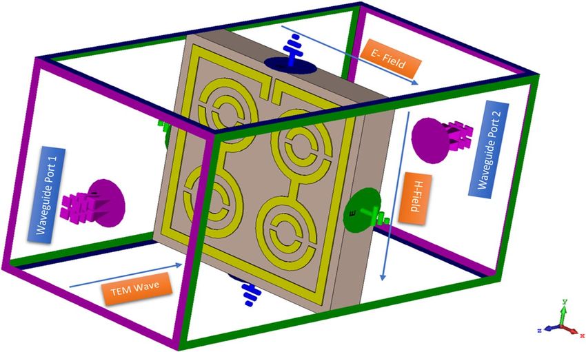
www.nature.com/scientificreports/
Figure 3. Design prototype of (a) unit cell (b) 1 × 2 array (c) experimental setup to measure the S-parameters
using waveguide.
2 (1 − V1 )
εr ∼ × . (9)
jk0 d (1 + V1 )
The effective permeability (μr) can be represented by,
2 (1 − V2 )
µr ∼ × . (10)
jk0 d (1 + V2 )
The refractive index (ηr) can be obtained through,
(S21 − 1)2 − S11 2
2
ηr = ×
, (11)
jk0 d (S21 + 1)2 − S11 2
2πf
where k0 = c .
The MATLAB code was used to extract the effective medium parameters using the above equations.
In order to measure the proposed metamaterial structure for validation of the simulated results, an Agilent
N5227 PNA Microwave Network Analyzer was used to extract the transmission coefficient (|S21|). The meta-
material structure prototype is placed in between the two waveguide ports such as A-INFOMW W/G to Coaxial
Adapter P/N:340WCAS (2.20–3.30 GHz), A-INFOMW W/G to Coaxial Adapter P/N:112WCAS (7.05–10.0 GHz)
and A-INFOMW W/G to Coaxial Adapter P/N:75WCAS (10–15 GHz). The Agilent N4694-60001 Electrical
Calibration Kit is used to calibrate the microwave network analyzer. Figure 3a,b indicates the prototype of the
fabricated metamaterial unit cell and array, whereas Fig. 3c shows the experimental setup.
Equivalent circuit model of the proposed MDD‑SRR metamaterial unit cell. The proposed meta-
material unit cell exhibited quintuple resonances due to the formation of an LC resonance circuit. The resonance
frequency of this circuit was measured using Eq. (12) 44.
1
f = √ , (12)
2π LC
where L is the inductance and C is the capacitance of the metamaterial structure. In the metamaterial unit cell,
the inductance was constructed by the metal strip and formed the capacitance by a split gap of the ring. The
capacitance is represented by:
A
C = ǫ0 ǫr , (13)
d
where ǫ0 is the permittivity in free space, ǫr is the relative permittivity, A is the area of split conducting strip, and
d is the split distance.
The whole inductance was measured based on the transmission line p rinciple45:
Scientific Reports | (2021) 11:19331 | https://doi.org/10.1038/s41598-021-98703-4 5
Vol.:(0123456789)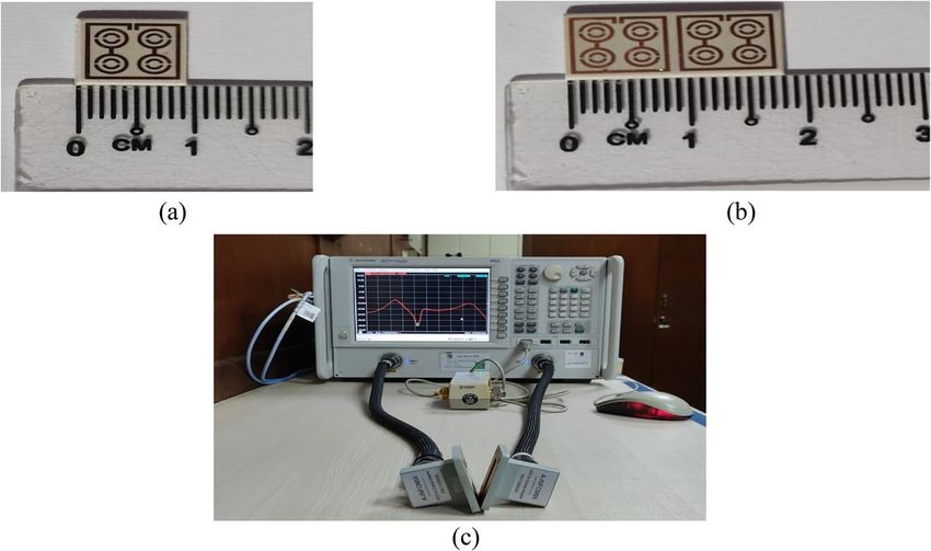
www.nature.com/scientificreports/
Figure 4. Equivalent circuit of the proposed unit cell.
�
2(d + g + h)2 (2w + g + h)2 + l 2
L = 0.01 × µ0 + t. (14)
(2w + g + h)2 (d + g + h)
Also, the whole capacitance was measured using:
2w + g + h 2(d + g + h)
C = ǫ0 ln t, (15)
2π(d + h)2 (a − l)
where ǫ0 = 8.854 × 10⁻¹² F/m, μ0 = 4π × 10–7 H/m, w is the microstrip line width, h is the substrate thickness, t is
the microstrip line thickness, and l is the length.
The approximated equivalent circuit of the proposed unit cell of an MDD-SRR-based metamaterial using
passive elements is depicted in Fig. 4, responsible for creating resonance in the construction of the metamate-
rial. The equivalent elements of the outer square ring contain two resonance frequencies which were generated
by L1, L2 and C1, C2. The half dumbbell-shaped ring contains two inductance and two capacitance values.
Whereas, the ring connector indicates the inductance value. One form of dumbbell shape is responsible for two
resonance frequencies. The values of inductance and capacitance were optimised in this equivalent circuit using
an ADS simulator. In this circuit, L1 and C1 are responsible for 2.896 GHz resonance frequency, meanwhile, the
combinations of L2 and C2, L3 and C3, L4 and C4, L5 and C5, L6 and C6, L7 and C7, L8 and C8, L9 and C9, L10
and C10, L11, L12 and C11 are respectively responsible for 8.11 GHz, 9.76 GHz, 12.48 GHz, and 13.49 GHz,
respectively. Simulation results of equivalent circuits were also accepted to compare and validate the simulation
results achieved through CST (Fig. 5).
Electromagnetic field analysis of proposed unit cell. In metallic conductors, the surface current rep-
resents the real electric current produced by an applied time-varying EM field. EM fields are generated by time-
varying electric charges in space that indicate the relationship between electric and magnetic fields. Maxwell and
the conventional law contributed several equations to explain the relationships among the material, E-field and
H-field, through the following Eqs. (16–17):
∂D ∂B
∇ ×H =J + and ∇ × E = − , (16)
∂t ∂t
D(t) = ε(t) × E(t) and B(t) = µ(t) × H(t), (17)
Scientific Reports | (2021) 11:19331 | https://doi.org/10.1038/s41598-021-98703-4 6
Vol:.(1234567890)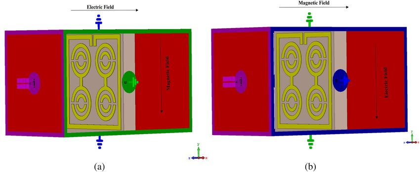
www.nature.com/scientificreports/
Figure 5. Simulated and equivalent results of |S21| of the proposed unit cell.
where E is time-varying electric intensities, H represent magnetic field intensities, D is time-varying electric
densities, B is magnetic flux densities, ɛ represents electric
permittivity,
μ is magnetic permeability, J is the time-
varying electric current density in a medium and ∇ = ∂x , ∂y , ∂z .
∂ ∂ ∂
The electromagnetic field analysis of the proposed unit cell can be clarified using the Eqs. (16–17). Figure 6
illustrates the surface current distribution of the proposed unit cell at the frequencies of 2.896 GHz, 8.11 GHz,
9.76 GHz, 12.48 GHz and 13.49 GHz. Based on Fig. 6a, the outer square ring provided a strong surface current
because it provided a low impedance path at 2.896 GHz. Moreover, the two dumbbell-shaped rings generated a
little bit of current. At 8.11 GHz, as indicated in Fig. 6b, the surface current was distributed uniformly. The lower
current densities were observed in all portion of the cells except the inner part of the dumbbell-shaped upper
circle. The two vertical edges and the upper horizontal edge of the outer square ring also contributed less to the
surface current flow due to the greater capacitive response for the split gap. Meanwhile, the current density in
the upper circle of the two dumbbell shapes increased rapidly at 9.76 GHz. According to Fig. 6c, the distributed
surface current was observed on three sides of the outer square ring at this frequency. The entire metamate-
rial unit cell except for the horizontal sides of the outer square ring contributed most of the surface current at
the resonance frequency of 12.48 GHz (Fig. 6d). Whereas, at 13.49 GHz, a lower current density was recorded
throughout the unit cell, as a high frequency causes an increase in impedance (Fig. 6e).
Based on the results, a good relationship between the surface current of the unit cell and the H-field was
observed, confirmed by Ampere’s law. Higher current increased the intensity of the H-field, hence, was noticeable
in the H-field (Fig. 8). From the study of the surface current in Fig. 6a, it was apparent that the surface current
density in the outer square ring was comparatively higher than that of the other parts. Therefore, the H-field
was strong in places with high current density (Fig. 8a). Meanwhile, the upper part of the outer square ring
manifested a very low current flow due to the split gap, resulting in the H-field being close to zero. On the other
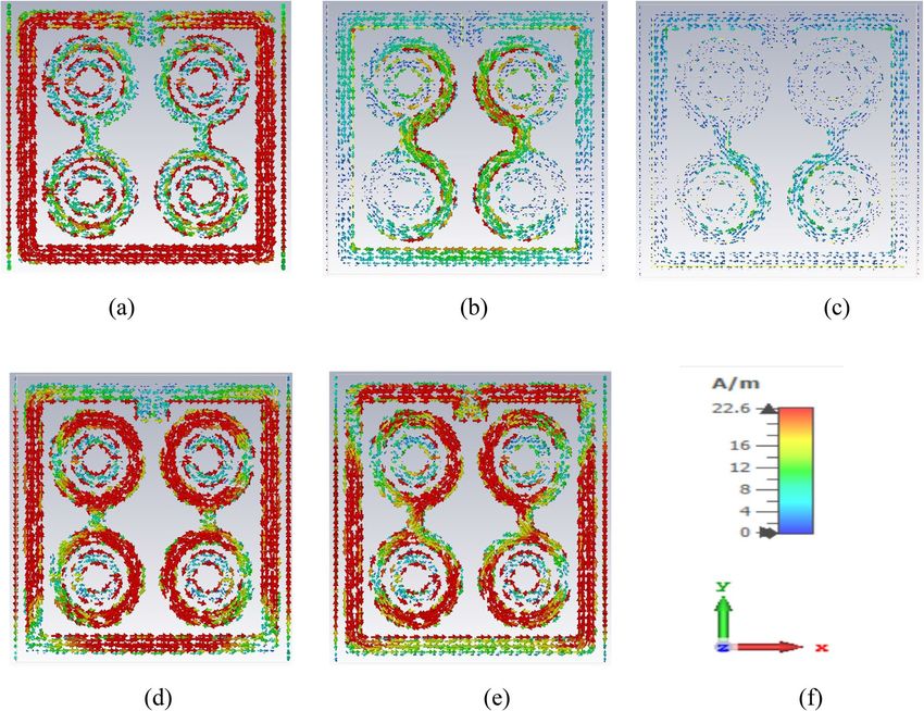
hand, the strength of the E-field gradually increased at the point of splits because the split in the outer square ring
forms the capacitor creating an additional electric field, as indicated in Fig. 7a. According to Maxwell Law, the
greater the amount of H-field in the outer square ring, the greater the amount of E-field on the opposite side of
the outer square ring, verified in Figs. 7 and 8. In short, the strength of the E-field increases if the rate of change
of the H-field is negative. Hence, it can be concluded that E-field and H-field models follow the relationships
depicted in Eqs. (16) and (17).
Results and discussion
The popular CST simulator acquired the S-parameters of the proposed MDD-SRR based unit cell, the reflec-
tion coefficient (|S11|) and transmission coefficient (|S21|) as depicted in Fig. 9a. The unit cell offered quintuple
resonances with frequencies of 2.896 GHz, 8.11 GHz, 9.76 GHz, 12.48 GHz and 13.49 GHz with an amplitude
of − 35.4 dB, − 33.4 dB, − 38.4 dB, − 34.7 dB and − 33.6 dB, respectively. Having said that, bandwidth is an
important component of satellite communications. The proposed unit cell in this study as depicted in Fig. 9a
displays excellent bandwidth with the value of transmission coefficient of less than − 10 dB in the ranges of
2.73–3.03 GHz, 7.75–8.29 GHz, 9.44–10.03 GHz, 12.33–12.57 GHz and 13.33–13.68 GHz. The reflection coef-
ficient (|S11|) of the unit cell exhibited five resonances at the frequencies of 3.85 GHz, 8.64 GHz, 10.99 GHz,
12.86 GHz and 14.93 GHz with an amplitude of − 34.36 dB, − 19.41 dB, − 17.73 dB, − 13.75 dB and − 13.15 dB,
respectively. Figure 9a demonstrates that each resonance frequency of the reflection coefficient is followed by
a maximum transmission coefficient. The permittivity and permeability along with boundary condition where
the magnetic field and electric field is travelled Y-axis and X-axis in a medium determine uniquely the response
Scientific Reports | (2021) 11:19331 | https://doi.org/10.1038/s41598-021-98703-4 7
Vol.:(0123456789)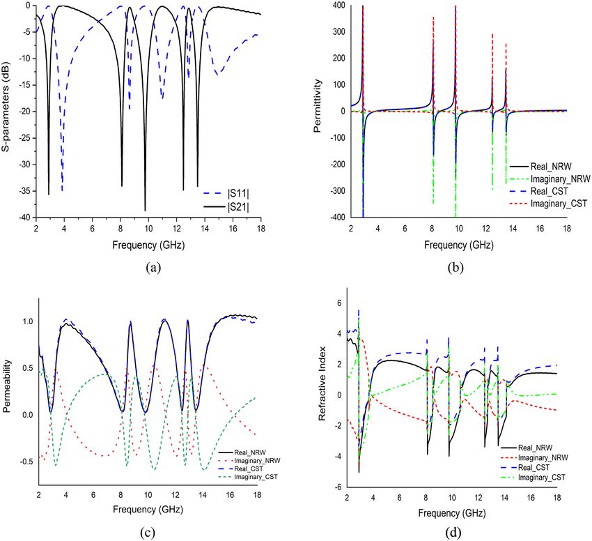
www.nature.com/scientificreports/

                                            Figure 6.  Surface current distribution of unit cell at (a) 2.896 GHz (b) 8.11 GHz (c) 9.76 GHz (d) 12.48 GHz
                                            (e) 13.49 GHz and (f) axis.

                                            of the artificial metamaterial unit cell design to an incoming time-varying electromagnetic wave which can be
                                            influenced by the change in the geometric shape of the proposed unit cell.
                                                There are several methods like the Drude method, TR-method, NRW method and Robust method used to
                                            obtain the effective parameter of a metamaterial. In this study, the NRW approach in MATLAB programming
                                            and the Robust retrieval method in CST was applied to extract the effective medium parameter response from
                                            S-parameters, as indicated in Fig. 9b,c. The recorded permittivity was negative at each resonance frequency with
                                            an amplitude of − 642, − 137, − 195, − 20 and − 60, respectively for both NRW and Robust methods, while the
                                            values of permeability measured were close to zero at each resonance with the amplitude of 0.034, 0.040, 0.035,
                                            0.047 and 0.050, respectively. Therefore, the proposed MDD-SRR based unit cell exhibited the ENG property,
                                            that can be used to increase the antenna bandwidth, microwave filter design, etc.46. The imaginary part of the
                                            permeability shows negative at every resonance frequency which is shown in Fig. 9c. Meanwhile, Fig. 9d indi-
                                            cates that the refractive index was negative at frequencies ranging between 2.912–3.664 GHz, 8.128–8.528 GHz,
                                            9.776–10.624 GHz, 12.496–12.704 GHz and 13.52–14.144 GHz with an amplitude of − 3.5, − 2.16, − 1.86,
                                            − 1.85 and − 1.82, respectively. Each of the negative maximum value of the refractive index occurred near the
                                            resonance frequency.
                                                The effective medium ratio (EMR) determined the goodness of the metamaterial unit cell design control
                                            for satellite communication. As indicated in Eq. (18), the EMR is calculated as the wavelength to dimension
                                            ratio of the metamaterial unit cell design. Negative permittivity is conceivable with the proposed metamaterial
                                            design if the EMR value is more than 4, which is an ideal number. The proposed metamaterial unit cell has an
                                            EMR of 11.51.
                                                                                                 Wavelength,
                                                                                      EMR =                         .                                    (18)
                                                                                                Unit cell length, L
                                                Similarly, HFSS was adopted to compare and justify the simulated results achieved using the CST simulator as
                                            illustrated in Fig. 10. The two simulators are considered in this study because each employs various techniques.
                                            CST operates according to the Finite Integral Technique (FIT) approach, while HFSS uses the Finite Element
                                            Method (FEM). Simulation results using HFSS have also been accepted to compare and validate the simulation
                                            results achieved with Computer Simulation Technology (CST) and are introduced in Fig. 10. The proposed unit
                                            cell displayed five resonances in both simulators with slight fluctuations in the last four resonance frequencies.

          Scientific Reports |   (2021) 11:19331 |               https://doi.org/10.1038/s41598-021-98703-4                                                 8

Vol:.(1234567890)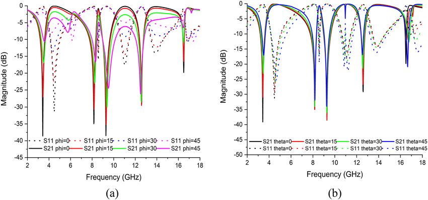
www.nature.com/scientificreports/

                                  Figure 7.  E-field distribution of unit cell at (a) 2.896 GHz (b) 8.11 GHz (c) 9.76 GHz (d) 12.48 GHz (e)
                                  13.49 GHz and (f) axis.

                                     The simulation and experimental results of the proposed metamaterial unit cell were in close agreement with
                                  each other for validation purposes, as shown in Fig. 11. The measured resonance frequencies of the metamaterial
                                  unit cell structure were 3.30 GHz, 8.26 GHz, 9.99 GHz, 12.56 GHz and 13.97 GHz, including the S, X and Ku band
                                  using Agilent N5227 PNA Microwave Network Analyzer. Because of the small manufacturing and calibration
                                  error and also the mutual resonance effect of the two waveguides, the measurement result remains only slightly
                                  inconsistent with the simulation result.

                                  Parametric studies. The effect of changing the various design steps. The metamaterial unit cell was devel-
                                  oped based on a trial-and-error method to obtain the maximum number of resonances with negative permittiv-
                                  ity and excellent EMR. Different designs were tested one after another until the desired property was achieved
                                  using the iterative method. The unit cell design began with the introduction of a square split ring resonator
                                  with a size of 9 mm on each side with an upper side split gap of 0.2 mm. This design exhibited three resonant
                                  frequencies that covered the S-, X-, and Ku-bands as illustrated in Fig. 12. In the next step, two circular rings
                                  with three separate split gaps were added to the square ring as indicated in Fig. 13. According to Fig. 12, an ad-
                                  ditional resonance at a frequency of 13.97 GHz was created by inserting it into a square ring. Two more rings
                                  with a split gap were installed vertically in Fig. 13 indicated additional resonance at 12.05 GHz with − 15 dB. The
                                  design was finalised by connecting the circular split rings vertically to create two dumbbell shape, as illustrated
                                  in Fig. 13. The design represented five main resonances around 2.896 GHz, 8.11 GHz, 9.76 GHz, 12.48 GHz and
                                  13.49 GHz, covering the frequency bands of S-, X- and Ku-bands satellite communications. Furthermore, the
                                  reflection coefficient of all the designs indicated the same resonant frequencies as the transmission coefficient
                                  as indicated in Fig. 14.

                                  The effects of modifying the split gap of rings. In this study, the effects of modifying the split gap of the whole
                                  ring on the proposed unit cell were also investigated. The |S21| of the metamaterial unit cell for different separate
                                  split gaps was introduced in Fig. 15. The resonance frequency of the unit cell depends on the electrical length of
                                  the copper and the split gap of the ring. As the split gap of the ring increases, the capacitance value decreases,
                                  affecting the resonant frequency towards a higher value (Fig. 15). The initial design depicted a whole split gap of
                                  the unit cell of 4 mm exhibiting the quintuple resonance frequency. The unit cell split gap was gradually reduced
                                  to 2 mm with a step size of 1 mm. The value of the resonance frequency was also observed to have reduced.
                                  Having said that, a 2 mm split gap also yielded the quintuple resonance frequency, but the value was reduced
                                  compared to others, indicating that the capacitive reactance is inversely proportional to frequency.

Scientific Reports |   (2021) 11:19331 |               https://doi.org/10.1038/s41598-021-98703-4                                                    9

                                                                                                                                                Vol.:(0123456789)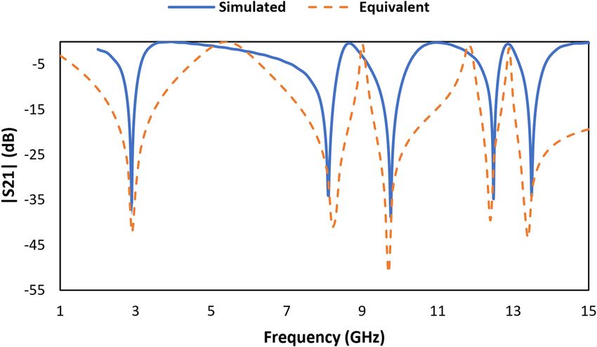
www.nature.com/scientificreports/

                                            Figure 8.  H-field distribution of unit cell at (a) 2.896 GHz (b) 8.11 GHz (c) 9.76 GHz (d) 12.48 GHz (e)
                                            13.49 GHz and (f) axis.

                                            The effects of changing the substrate properties. The study also examined the effects of changing the substrate
                                            material of the unit cell. This analysis used three Rogers variants with the most commonly used FR-4 materials.
                                            The first study used the FR-4 (lossy) with a thickness of 1.6 mm, electric permittivity of 4.3 and dielectric loss of
                                            0.025. Figure 16 indicates that this material exhibited five resonances frequency with a lower resonance peak and
                                            a narrower bandwidth but higher EMR compared to others. Meanwhile, Rogers RT 5880 (lossy) with a thick-
                                            ness of 1.575 mm, electric permittivity of 2.2 and dielectric loss of 0.0009 also exhibits the same response as the
                                            previous design, with an acceptable magnitude. However, two more experiments were performed using Rogers
                                            RT 6002 (lossy and loss-free) with a thickness of 1.524 mm, electric permittivity of 2.94, the dielectric loss of
                                            0.0012 (lossy). Both substrate materials demonstrated the same frequency band with an acceptable magnitude
                                            as depicted in Fig. 16. Comparatively, the resonance peak of Rogers RT 6002 (lossy) was higher compared to the
                                            others. Since RT 6002 (lossy) covered maximum bands with acceptable resonance peak and excellent EMR, the
                                            proposed metamaterial unit cell was outlined on this material.

                                            The effects of changing the EM field propagation. The simulation setup can be represented based on the different
                                            orientations of EM propagation in Fig. 18. An EM field was propagated along the Z-axis, where electric and mag-
                                            netic fields were perpendicular to each other. According to Fig. 18a, the E-field operated on the X-axis, while the
                                            H-field acted on the Y-axis. In this orientation, the metamaterial unit cell exhibited five resonance frequencies
                                            for both |S21| and |S11|, as indicated in Fig. 17. On the other hand, when the E-field acted on the Y-axis and the
                                            H-field on the X-axis (Fig. 18b), the metamaterial unit cell of this orientation yielded two resonance frequencies
                                            for both |S21| and |S11| (Fig. 17). However, only the first orientation was selected because it matched the purpose
                                            of this research.

                                            The effects of polarisation and incident angle on metamaterial unit cell. Figure 19a,b illustrate the changes in
                                            reflection and transmission coefficients with the frequencies of EM waves for the polarisation (Φ) and incident
                                            angle (θ) from 0° to 45°. The numerical simulation was well performed in a high-frequency EM simulator CST
                                            microwave studio. Both graphs indicated that when phi or theta increases, the metamaterial revealed incompat-
                                            ible intensities for all resonant frequencies. However, both features produced the same number of resonance
                                            frequencies with the metamaterial unit cell. Hence, this metamaterial unit cell enabled polarisation and incident
                                            angle insensitivity.

                                            Array metamaterial results. Despite the advantages, metamaterial unit cell arrays need to be inspected
                                            because a simple unit cell does not work independently in many practical situations. The different arrangements

          Scientific Reports |   (2021) 11:19331 |               https://doi.org/10.1038/s41598-021-98703-4                                                   10

Vol:.(1234567890)
www.nature.com/scientificreports/
Figure 9. Simulated results of the proposed unit cell (a) Scattering parameters, (b) Permittivity graph, (c)
Permeability graph, and (d) Refractive index graph.
Figure 10. S-parameter results of MDD-SRR unit cell using CST and HFSS simulator.
in an array are described to assess the effects of coupling between the unit cells, as indicated in Fig. 20. The |S21|
of the proposed MDD-SRR unit cell 1 × 1 (9 × 9 mm2), 1 × 2 (9 × 18 mm2), 2 × 2 (18 × 18 mm2), 8 × 8 (72 × 72
mm2) has been displayed in Fig. 21. Figure 21 illustrates the transmission coefficient of both arrays displaying an
equal response since the proposed unit cell exhibited quintuple resonance frequencies. This numerical simula-
tion setup was implemented using the CST microwave simulator. The first resonance peak of the 2 × 2 and 8 × 8
Scientific Reports | (2021) 11:19331 | https://doi.org/10.1038/s41598-021-98703-4 11
Vol.:(0123456789)www.nature.com/scientificreports/
Figure 11. The transmission coefficient results of MDD-SRR unit cell using CST and experimental.
Figure 12. The transmission coefficient graph based on various design steps.
Figure 13. Various step to finalize the MDD-SRR structure.
arrays was higher than the others because an array is more modified by harmonics at higher frequencies. The
simulated and experimental results of 1 × 2 array have been shown in Fig. 22. It is observed from Fig. 22 that
the measured results of 1 × 2 array exhibit same resonances as the simulated results using CST software. The
measured resonance frequencies of the 1 × 2 array are 3.05 GHz, 8.09 GHz, 9.75 GHz, 11.90 GHz and 14 GHz,
including the S, X and Ku band using two waveguide ports. In addition, the result of the array shows some mis-
matching at resonance frequencies. But the results show that the array outcome is very similar to the unit cell
results showing quintuple resonances. Minor discrepancies may be due to the manufacturing defects and mutual
coupling effect.
Conclusion
This study examined the metamaterial with an MDD-SRR indicating quintuple resonances in S-, X-, and Ku-
bands over the operating frequency range of 2–18 GHz. The metamaterial unit cell was created on Rogers RT
6002 with a dimension of 9 × 9 mm2. The scattering parameters were measured using CST EM field simulation
software, whereas the effective medium parameters were computed using the Robust method and NRW methods.
Scientific Reports | (2021) 11:19331 | https://doi.org/10.1038/s41598-021-98703-4 12
Vol:.(1234567890)www.nature.com/scientificreports/
Figure 14. The reflection coefficient graph based on different design steps.
Figure 15. The transmission coefficient graph based on various split gap.
Figure 16. The transmission coefficient graph for different substrate.
Both methods yielded similar results. The scattering parameters of the metamaterial unit cell was also verified
using the Advanced Design System software to optimise the equivalent circuit model and HFSS. The results of
the 1 × 2, 2 × 2 and 8 × 8 arrays analysed with the unit cell yielded a good agreement. The simulation result is
confirmed by the experimental measurement of proposed unit cell and 1 × 2 array. The measured results show
great similarity with the simulated results. The proposed unit cell provided an excellent EMR of 11.51 with proven
compactness and criteria met, L < λ/4. The negative permittivity, negative refractive index and near-zero perme-
ability properties proposed by the unit cell can also be used to improve the performance of different microwave
frequency devices due to the moderate unit cell size and high EMR. The S- and X-bands are mostly used in
Scientific Reports | (2021) 11:19331 | https://doi.org/10.1038/s41598-021-98703-4 13
Vol.:(0123456789)www.nature.com/scientificreports/
Figure 17. S-parameter for different orientation based on propagation of electromagnetic field.
Figure 18. Different orientation of electromagnetic field propagation (a) Ex-Hy and (b) Ey-Hx.
Figure 19. S-parameter for proposed unit cell based on (a) polarisation and (b) incident angle.
Scientific Reports | (2021) 11:19331 | https://doi.org/10.1038/s41598-021-98703-4 14
Vol:.(1234567890)www.nature.com/scientificreports/
Figure 20. Various types of array (a) 1 × 2 (b) 2 × 2 (c) 8 × 8 (d) axis.
Figure 21. Transmission coefficient results of proposed unit cell, 1 × 2, 2 × 2, and 8 × 8 array.
Scientific Reports | (2021) 11:19331 | https://doi.org/10.1038/s41598-021-98703-4 15
Vol.:(0123456789)www.nature.com/scientificreports/
Figure 22. Transmission coefficient results of 1 × 2 array using CST and experimental.
airport surveillance radar, weather radar and communication satellites. Meanwhile, the Ku-band is commonly
employed in satellite TV networks. Therefore, the metamaterial unit cell design outlined in this work can be
effectively used in satellite.
Received: 16 June 2021; Accepted: 7 September 2021
References
1. Viktor, G. & Veselago, P. N. L. The electrodynamics of substances with simultaneously negative values of ɛ and μ. Sov. Phys. Uspekhi
10, 509–514. https://doi.org/10.1070/pu1968v010n04abeh003699 (1968).
2. Smith, D. R., Padilla, W. J., Vier, D. C., Nemat-Nasser, S. C. & Schultz, S. Composite medium with simultaneously negative perme-
ability and permittivity. Phys. Rev. Lett. 84, 4184–4187. https://doi.org/10.1103/physrevlett.84.4184 (2000).
3. Nasimuddin, N., Chen, Z. N. & Qing, X. Bandwidth enhancement of a single-feed circularly polarized antenna using a metasurface:
Metamaterial-based wideband CP rectangular microstrip antenna. IEEE Antennas Propag. Mag. 58, 39–46. https://d oi.o
rg/1 0.1 109/
map.2016.2520257 (2016).
4. Zhou, E., Cheng, Y., Chen, F. & Luo, H. Wideband and high-gain patch antenna with reflective focusing metasurface. AEU-Int. J.
Electron. C. 134, 153709. https://doi.org/10.1016/j.aeue.2021.153709 (2021).
5. Puentes, M., Maasch, M., Schubler, M. & Jakoby, R. Frequency multiplexed 2-dimensional sensor array based on split-ring reso-
nators for organic tissue analysis. IEEE Trans. Microw. Theory Tech. 60, 1720–1727. https://doi.org/10.1109/tmtt.2012.2189241
(2012).
6. Grbic, A. & Eleftheriades, G. V. Overcoming the diffraction limit with a planar left-handed transmission-line lens. Phys. Rev. Lett.
https://doi.org/10.1103/physrevlett.92.117403 (2004).
7. Schurig, D. et al. Metamaterial electromagnetic cloak at microwave frequencies. Science 314, 977–980. https://doi.org/10.1126/
science.1133628 (2006).
8. Hossain, M., Mohammad, R. I. F., Islam, M. & Hanafi, N. Application of auxiliary antenna elements for SAR reduction in the
human head. Adv. Mater. Res. 974, 288–292. https://doi.org/10.4028/www.scientific.net/AMR.974.288 (2014).
9. Faruque, M. R. I., Islam, M. T. & Ali, M. A. M. A new design of metamaterials for SAR reduction. Meas. Sci. Rev. 13, 70–74. https://
doi.org/10.2478/msr-2013-0011 (2013).
10. Ahamed, E. et al. Enhancement of magnetic field intensity with a left-handed metamaterial tunnel resonator for obstacle sensing.
Chin. J. Phys. 70, 91–105. https://doi.org/10.1016/j.cjph.2020.12.020 (2021).
11. Abdulkarim, Y. I. et al. Corrigendum to “Design and study of a metamaterial based sensor for the application of liquid chemicals
detection” J Mater Res Technol Volume 9 (5) (September–October 2020) 10291–10304. J. Market. Res. 11, 196. https://doi.org/10.
1016/j.jmrt.2021.01.020 (2021).
12. Baqir, M. A. & Choudhury, P. K. Hyperbolic metamaterial-based UV absorber. IEEE Photonics Technol. Lett. 29, 1548–1551. https://
doi.org/10.1109/lpt.2017.2735453 (2017).
13. Wang, Q. & Cheng, Y. Compact and low-frequency broadband microwave metamaterial absorber based on meander wire structure
loaded resistors. AEU-Int. J. Electron. C. 120, 153198. https://doi.org/10.1016/j.aeue.2020.153198 (2020).
14. Deng, G. et al. An ultrathin, triple-band metamaterial absorber with wide-incident-angle stability for conformal applications at
X and Ku frequency band. Nanoscale Res. Lett. https://doi.org/10.1186/s11671-020-03448-0 (2020).
15. Bakır, M. et al. Tunable energy harvesting on UHF bands especially for GSM frequencies. Int. J. Microw. Wirel. Technol. 10, 67–76.
https://doi.org/10.1017/s1759078717001325 (2017).
16. Bağmancı, M. et al. Wide band fractal-based perfect energy absorber and power harvester. Int. J. RF Microw. Comput. Aided Eng.
https://doi.org/10.1002/mmce.21597 (2018).
17. Fan, J. & Cheng, Y. Broadband high-efficiency cross-polarization conversion and multi-functional wavefront manipulation based
on chiral structure metasurface for terahertz wave. J. Phys. D Appl. Phys. 53, 025109. https://doi.org/10.1088/1361-6463/ab4d76
(2019).
18. Yuan, Y. et al. Independent phase modulation for quadruplex polarization channels enabled by chirality-assisted geometric-phase
metasurfaces. Nat. Commun. https://doi.org/10.1038/s41467-020-17773-6 (2020).
19. Cheng, Y., Fan, J., Luo, H. & Chen, F. Dual-band and high-efficiency circular polarization convertor based on anisotropic meta-
material. IEEE Access 8, 7615–7621. https://doi.org/10.1109/access.2019.2962299 (2020).
20. Zhang, K. et al. Polarization-engineered noninterleaved metasurface for integer and fractional orbital angular momentum multi-
plexing. Laser Photonics Rev. 15(1), 2000351. https://doi.org/10.1002/lpor.202000351 (2020).
21. Zhang, K. et al. Phase-engineered metalenses to generate converging and non-diffractive vortex beam carrying orbital angular
momentum in microwave region. Opt. Express 26(2), 1351. https://doi.org/10.1364/oe.26.001351 (2018).
22. Azeez, A. R., Elwi, T. A. & Al-Hussain, Z. A. A. Design and analysis of a novel concentric rings based crossed lines single negative
metamaterial structure. Eng. Sci. Technol. Int. J. 20, 1140–1146. https://doi.org/10.1016/j.jestch.2016.11.010 (2017).
Scientific Reports | (2021) 11:19331 | https://doi.org/10.1038/s41598-021-98703-4 16
Vol:.(1234567890)www.nature.com/scientificreports/
23. Almutairi, A. F. et al. A complementary split ring resonator based metamaterial with effective medium ratio for C-band microwave
applications. Results Phys. 15, 102675. https://doi.org/10.1016/j.rinp.2019.102675 (2019).
24. Islam, S. S., Faruque, M. R. I. & Islam, M. T. An ENG metamaterial based wideband electromagnetic cloak. Microw. Opt. Technol.
Lett. 58, 2522–2525. https://doi.org/10.1002/mop.30084 (2016).
25. Islam, M. S. et al. A gap coupled hexagonal split ring resonator based metamaterial for S-band and X-band microwave applications.
IEEE Access 8, 68239–68253. https://doi.org/10.1109/access.2020.2985845 (2020).
26. Liu, S.-H., Guo, L.-X. & Li, J.-C. Left-handed metamaterials based on only modified circular electric resonators. J. Mod. Opt. 63,
2220–2225. https://doi.org/10.1080/09500340.2016.1189008 (2016).
27. Tamim, A. M., Faruque, M. R. I., Alam, M. J., Islam, S. S. & Islam, M. T. Split ring resonator loaded horizontally inverse double
L-shaped metamaterial for C-, X- and Ku-Band Microwave applications. Results Phys. 12, 2112–2122. https://doi.org/10.1016/j.
rinp.2019.02.033 (2019).
28. Bouzouad, M., Chaker, S. M., Bensafielddine, D. & Laamari, E. M. Gain enhancement with near-zero-index metamaterial super-
strate. Appl. Phys. A 121, 1075–1080. https://doi.org/10.1007/s00339-015-9206-0 (2015).
29. Islam, S. S., Faruque, M. R. I. & Islam, M. T. Design of a new ENG metamaterial for S-band microwave applications. J. Electr.
Electron. Eng. 7(2), 13 (2014).
30. Siddiky, A. M., Faruque, M. R. I. & Islam, M. T. Double H-shaped complementary split ring resonator with different orientations
for quad-band satellite applications. Results Phys. 19, 103427. https://doi.org/10.1016/j.rinp.2020.103427 (2020).
31. Ramachandran, T., Faruque, M. R. I. & Ahamed, E. Composite circular split ring resonator (CSRR)-based left-handed metamaterial
for C- and Ku-band application. Results Phys. 14, 102435. https://doi.org/10.1016/j.rinp.2019.102435 (2019).
32. Moniruzzaman, M. et al. Cross coupled interlinked split ring resonator-based epsilon negative metamaterial with high effective
medium ratio for multiband satellite and radar communications. Results Phys. 18, 103296 (2020).
33. Ahamed, E., Faruque, M. R. I., Mansor, M. F. B. & Islam, M. T. Polarization-dependent tunneled metamaterial structure with
enhanced felds properties for X-band application. Results Phys. 15, 102530 (2019).
34. Zarghooni, B., Dadgarpour, A. & Denidni, T. A. Greek-key pattern as a miniaturized multiband metamaterial unit-cell. IEEE
Antennas Wirel. Propag. Lett. 14, 1254–1257 (2015).
35. Alkurt, F. O. et al. Antenna-based microwave absorber for imaging in the frequencies of 1.8, 2.45, and 5.8 GHz. Opt. Eng. 57,
113102 (2018).
36. Bakır, M. et al. Metamaterial based energy harvesting for GSM and satellite communication frequency bands. Opt. Eng. 57, 087110
(2018).
37. Turkmen, O., Ekmekci, E. & Turhan-Sayan, G. Nested U-ring resonators: A novel multiband metamaterial design in microwave
region. IET Microw. Antennas Propag. 6, 1102–1108 (2012).
38. Ramachandran, T., Faruque, M. R. I. & Islam, M. T. A compact square shaped left-handed passive metamaterial with optimized
quintuple resonance frequencies for satellite applications. Chin. J. Phys. 67, 360–375 (2020).
39. Ahamed, E. et al. Left-handed metamaterial inspired by joint T–D geometry on flexible NiAl2O4 substrate. PLoS One 13(6), 1–28
(2018).
40. Islam, S. S., Rahman, M. A., Faruque, M. R. I. & Islam, M. T. Design and analysis with different substrate materials of a new meta-
material for satellite applications. Sci. Engg. Comp. Mats, 25(1), 59–66. https://doi.org/10.1515/secm-2015-0526 (2016).
41. Chen, X., Grzegorczyk, T. M., Wu, B.-I., Pacheco, J. Jr. & Kong, J. A. Robust method to retrieve the constitutive effective parameters
of metamaterials. Phys. Rev. E 70(1), 016608 (2004).
42. Rothwell, E. J., Frasch, J. L., Ellison, S. M., Chahal, P. & Ouedraogo, R. O. Analysis of the Nicolson–Ross–Weir method for char-
acterizing the electromagnetic properties of engineered materials. Prog. Electromagn. Res. 157, 31–47 (2016).
43. Castanié, A., Mercier, J.-F., Félix, S. & Maurel, A. Generalized method for retrieving effective parameters of anisotropic metama-
terials. Opt. Express 22, 29937. https://doi.org/10.1364/oe.22.029937 (2014).
44. Gay-Balmaz, P. & Martin, O. J. Electromagnetic resonances in individual and coupled split-ring resonators. J. Appl. Phys. 92(5),
2929–2936 (2002).
45. Paul, C. R. Inductance: Loop and Partial. (Wiley, 2010) ISBN 978-0-470-46188-4.
46. Dawar, P. & De, A. Bandwidth enhancement of RMPA using ENG metamaterials at THz. In 2013 4th International Conference on
Computer and Communication Technology (ICCCT). 11–16 (2013).
Acknowledgements
This work was supported by the Research Universiti Grant, Universiti Kebangsaan Malaysia, Dana Impak Perdana
(DIP), code: DIP 2020–018.
Author contributions
M.B.H. gave significant involvement to design, analysis, characterization, and application. M.R.I.F. contributed to
the conception, supervision, funding and critical revision of the article for important intellectual content. S.S.I.
provided necessary instructions for initial conception and analytical purposes and M.T.I. provided necessary
instructions for experimental purposes.
Competing interests
The authors declare no competing interests.
Additional information
Correspondence and requests for materials should be addressed to M.R.I.F.
Reprints and permissions information is available at www.nature.com/reprints.
Publisher’s note Springer Nature remains neutral with regard to jurisdictional claims in published maps and
institutional affiliations.
Scientific Reports | (2021) 11:19331 | https://doi.org/10.1038/s41598-021-98703-4 17
Vol.:(0123456789)www.nature.com/scientificreports/
Open Access This article is licensed under a Creative Commons Attribution 4.0 International
License, which permits use, sharing, adaptation, distribution and reproduction in any medium or
format, as long as you give appropriate credit to the original author(s) and the source, provide a link to the
Creative Commons licence, and indicate if changes were made. The images or other third party material in this
article are included in the article’s Creative Commons licence, unless indicated otherwise in a credit line to the
material. If material is not included in the article’s Creative Commons licence and your intended use is not
permitted by statutory regulation or exceeds the permitted use, you will need to obtain permission directly from
the copyright holder. To view a copy of this licence, visit http://creativecommons.org/licenses/by/4.0/.
© The Author(s) 2021
Scientific Reports | (2021) 11:19331 | https://doi.org/10.1038/s41598-021-98703-4 18
Vol:.(1234567890)You can also read