2021 POWERFLY FULL SUSPENSION - SERVICE MANUAL SUPPLEMENT
←
→
Page content transcription
If your browser does not render page correctly, please read the page content below

2021 POWERFLY FULL SUSPENSION
      SERVICE MANUAL SUPPLEMENT
2021 Powerfly Full Suspension service manual supplement 2021 Powerfly Full Suspension service manual supplement
Table of Contents Install the rear fender and rear rack
Install the rear fender and rear rack 1 The rear fender and the rear rack are installed TWO
together as an assembly. CONNECTIONS
Install the rear mini fender 2 AT SEATSTAY
Install the front fender 2 1. Remove the rear wheel. (INSIDE)
Remove the rear shock 3
Install the rear shock 4 2. From the underside of the fender, use the two REAR STRUT
M5x0.8x14mm button head bolts and M5 flat CONNECTIONS
Install the rear derailleur hanger 5
washers to attach the rack to the fender.
Cable routing 6
Remove the early Bosch RIB system 7
Install the early Bosch RIB system 9 NOTE Make sure these bolts have
Remove the new RIB system 10 threadlocker applied.
Install the new RIB system 11 a. If you are reusing these bolts, clean
7. Attach the fender/rack struts to the holes at
the rear of each chainstay.
Bosch drive unit removal/installation 15 with isopropyl alcohol and apply Loctite
Aftermarket spec limitations 15 242 threadlocker or similar prior to
attachment. NOTE Make sure chainstay bolts have
TWO CONNECTIONS threadlocker applied.
UNDERSIDE OF FENDER
a. If you are reusing the chainstay bolts,
clean with isopropyl alcohol and apply
Loctite 242 threadlocker or similar prior
to attachment.
8. Torque the chainstay bolts to 6Nm.
3. Torque the two bolts to 6Nm.
4. Route the rear light cable connections up
through the inside of the non-driveside rack
strut.
NOTE The light cable connectors are on
the inside of the non-driveside chainstay.
5. Connect the cable connections to the rear
light.
6. Attach the fender/rack to the two holes at the
top of the seatstay.
NOTE This manual has the unique design
features and components for the 2021 Powerfly
FS bicycle.
1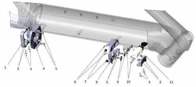
2021 Powerfly Full Suspension service manual supplement                                                                   2021 Powerfly Full Suspension service manual supplement

Install the rear mini fender                                       Install the front fender                               Remove the rear shock
1.     Remove the rear wheel.
                                                                             NOTE
                                                                                                                          1.     Remove the rear fender.
                                                                                       The 27.5 model has a different
2.     Use the two M5x0.8x14mm bolts and flat                           front fender than the 29er model.                 2.     Remove the rear wheel.
       washers to attach the mini fender to the two
       holes at the top of the seatstay.                           1.     Use an M5 bolt and washer to attach the         3.     Remove the end cap bolt (non-drive side) and
                                                                          U-shaped front fender strut to the fender.             the rocker pivot axle (drive side).
          NOTE     Make sure these bolts have
     threadlocker applied.                                                          LOWER FORK
                                                                                                                                   NOTE
                                                                                          ARCH                                               Do not remove the bearings and
       a. If you are reusing these bolts, clean                                                                                spacers at this pivot location.
          with isopropyl alcohol and apply Loctite                              FENDER STRUT
          242 threadlocker or similar prior to
          attachment.                                                                                                                                      UPPER SHOCK-MOUNT
                                                                                                                                                           AXLE-BOLT
                                                                                                           STRUT TO
3.     Torque the bolts to 6Nm.
                                                                                                           FRONT FORK

                                                                                                                                                             ROCKER PIVOT AXLE

           TWO BOLTS                    MINI FENDER
           & WASHERS

                                                                   2.     Torque the bolt to 2.5Nm.

                                                                   3.     Use an M6 bolt to attach the fender and strut
                                                                          assembly to the lower fork arch.

                                                                             NOTE
                                                                                                                          4.     Pivot the seatstay rearward to expose the top
                                                                                     Make sure the lower fork arch bolt          shock mount.
                                                                        has threadlocker applied.
                                                                                                                          5.     Remove the upper shock-mount axle-bolt.
                                                                          a. If you are reusing the fork arch bolt,
                                                                             clean with isopropyl alcohol and apply       6.     Remove the lower shock-mount axle-bolt from
                                                                             Loctite 242 threadlocker or similar prior           the shock rotation linkage.
                                                                             to attachment.

                                                                   4.     Torque the bolt to 9Nm.                                    LOWER SHOCK-MOUNT
                                                                                                                                              AXLE-BOLT

                                                                   5.     Use two M5 bolts to attach the struts to the
                                                                                                                                  SHOCK ROTATION
                                                                          front fork.                                                    LINKAGE

                                                                             NOTE     Make sure the strut bolts have
                                                                        threadlocker applied.

                                                                          a. If you are reusing the strut bolts, clean
                                                                             with isopropyl alcohol and apply Loctite
                                                                             242 threadlocker or similar prior to
                                                                             attachment.

                                                                   6.     Torque the strut bolts to 6Nm.

                                                          2                                                                                                                         3
2021 Powerfly Full Suspension service manual supplement 2021 Powerfly Full Suspension service manual supplement
Install the rear shock 8. Grease the non-driveside bearing bore. Install the rear derailleur hanger
1. Attach the lower shock-mount axle-bolt in the
9. With the spacer, bearing and rocker pivot axle
shock rotation linkage. CAUTION: Do not apply grease between the
installed from the drive side, install the end hanger and the bicycle frame.
cap bolt in the non-drive side.
LOWER SHOCK-MOUNT CAUTION: Do not apply grease to the UDH bolt
AXLE-BOLT NOTE threads.
Make sure there is a spacer inside
and a bearing outside in the seatstay hole.
SHOCK ROTATION
LINKAGE
1. Insert the hanger on the inside of the driveside
10. Torque the rocker pivot axle to 17Nm. chainstay (2-piece swing arm) and attach with
the hanger bolt (left-hand thread).
11. See page 1 to reinstall the rear fender and
rear rack, or page 2 to reinstall the rear mini REAR
fender. DERAILLEUR HANGER
HANGER BOLT
2. Torque the bolt to 10Nm.
3. Attach the upper shock-mount axle-bolt.
UPPER SHOCK-MOUNT
AXLE-BOLT
ROCKER PIVOT AXLE
2. Make sure to have the hanger in the correct
position as shown.
4. Torque the bolt to 10Nm.
5. Pivot the seatstay forward to align the rocker
pivot axle with the seatstay mounting hole.
6. Grease the driveside bearing bore.
7. Insert the rocker pivot axle (drive side).
3. Torque the hanger bolt to 25Nm (left-hand
thread).
NOTE Make sure there is a spacer inside
and a bearing outside in the seatstay hole.
4 52021 Powerfly Full Suspension service manual supplement 2021 Powerfly Full Suspension service manual supplement
Cable routing Remove the early Bosch RIB system
NOTE The rear light cable routes through
Cable Color
the non-driveside chainstay, then up internally NOTE
Shifter Red This can be done without removing
through the rack strut to the light.
Dropper Black the drive unit from the bike frame.
Controller Green
Rear brake Blue NOTE Save all fasteners, bumpers, and
Battery power Gray lock assembly for installation.
Rear light Pink
Speed sensor Yellow
Charge port Orange Parts list
1. Lower docking bracket
2. Two nylon-insert locknuts (M5) from the upper
and lower docking brackets
3. Four T25 security screws
4. Powertube connector plate
5. Two button head cap screws (M5x.8x16mm) from
DROPPER POST the upper and lower docking brackets
6. Two countersunk bolts (M4x0.7x8mm)
7. Two bumpers
REAR BRAKE HOUSING 8. Lock cover
9. Two washers
10. Lock assembly
11. Upper docking bracket
REAR LIGHT BATTERY POWER
CONTROLLER
REAR DERAILLEUR
6 72021 Powerfly Full Suspension service manual supplement 2021 Powerfly Full Suspension service manual supplement
Remove the early Bosch RIB system 12. Remove the two T25 security screws (3), the Install the early Bosch RIB system
locknuts (2), and the lower docking bracket
1. Remove the RIB battery from the downtube. (1). Completely remove the lower docking sub- 1. Check that the cables running along the
assembly from the bicycle. bottom and/or top of the down tube are firmly
2. Note the cable routing paths. The cable routing held in place and in the same routing paths
will be the same for the installation. 13. If installing the new RIB system, remove the from the removal.
existing battery connection plug from the lower
3. Remove the key from the battery lock. connector plate (4). 2. Use the two T25 security screws (3), the
locknuts (2) to install the lower docking
4. Remove the two bolts (6), the two bumpers bracket (1).
(7), and the lock cover (8) from the upper NOTE To aid removal, you may need to
docking. use a pair of cutters to clip off some or all of the 3. Carefully connect the battery plug in the
plastic hooks as shown. This plastic connector connector plate (4) to the battery connection
5. Remove the two button head screws (5), the plate will not be reused with the new RIB system. on the drive unit.
washers (9), and the lock assembly (10).
4. Use the two button head screws (5) to install
6. Remove the two T25 security screws (3) and the connector plate (4).
the two locknuts (2), and the upper docking
lock (11). 5. Use the two T25 security screws (3) and the
two locknuts (2) to install the upper docking
7. Set aside the screws (5), (6), bumpers (7), and lock (11).
locknuts (2) for reuse.
6. Use the two button head screws (5), the
8. Set aside the lock assembly (10) for re- washers (9) to install the lock assembly (10).
installation.
7. Use the two bolts (6), the two bumpers (7) to
9. Remove the two button head screws (5) from install the lock cover (8) to the upper frame
the lower docking. docking.
10. Carefully extract the connector plate (4) and 8. Insert the key into the battery lock.
find the connection point for the battery plug.
9. Install the RIB battery in the down tube.
11. Disconnect this connection point from the
battery plug. 10. To test the connection, try to slide the battery
toward the head tube with the system powered
on.
11. Update the software per the manufacturer’s
process.
12. Perform the battery install and eject standard
operating procedure.
8 92021 Powerfly Full Suspension service manual supplement 2021 Powerfly Full Suspension service manual supplement
Remove the new RIB system Remove the new RIB system Install the new RIB system
Parts list
1. Remove the RIB battery from the down tube. 1. Install the existing battery connection plug into
Description Item # the new lower battery plug mounting cover (E).
NOTE: The lettered parts are for the new RIB system. 2. Note the cable routing paths. The cable routing
The numbered parts are re-used from the old RIB will be the same for the installation.
NOTE Make sure the cables running along
system.
A. A
lignment plate PN W5252100 (500Wh) 3. Remove the key from the battery lock. the bottom and/or top of the down tube are firmly
Length of plate corresponds to length of battery held in place.
opening in down tube. PN W5252805 (625Wh) 4. Remove the two bolts (6), the two bumpers
B. Lower metal docking bracket (7), and the upper plastic lock cover (F).
Kit PN 5256255
C. Upper metal docking bracket 5. Remove the plunger (11) and the lock
BATTERY
CONNECTION PLUG
assembly (10).
D. Two 6mm button head screws (with threadlocker)
Kit PN 5257257
2. Two nylon-insert locknuts (M5) 6. Remove the two button head screws (5) and
the washers (H) from the upper metal docking
5. Two button head cap screws (M5x.8x16mm) bracket (C).
MOUNTING COVER (E)
6. Two countersunk bolts (M4x0.7x8mm)
7. Remove two button head screws (5) and the
G. Four 16mm T25 security screws (no threadlocker) lower battery-plug mounting cover (E) with the
battery plug. 2. Use one button head screw (D) each to pre-
H. Two 10mm washers assemble the alignment plate (A) with the
E. Lower battery-plug mounting cover 8. Thread the battery plug connection through the
lower metal docking bracket (B) and the upper
metal docking bracket (C).
lower metal docking bracket (B) and remove
F. Upper plastic lock cover Kit PN 5256256 the plug connection.
7. Two bumpers
9. Remove the four T25 security screws (G) and
10. Lock assembly PN W591941 the locknuts (2) to remove the alignment plate
(1) with the upper (C) and lower (B) docking
11. Plunger PN 564539 brackets as a sub-assembly.
10. Remove the two button head screws (D), and
the upper (C) and lower (B) docking brackets
BATTERY
CONNECTION from the alignment plate (A).
PLUG
10 112021 Powerfly Full Suspension service manual supplement 2021 Powerfly Full Suspension service manual supplement
3. Torque the two screws (D) to 3Nm. 4. Place the sub-assembly into the down tube. 8. At the lower bracket, thread the battery plug 12. Reuse the two bolts (6) and the two bumpers
connection through the new lower metal (7) to install the upper plastic lock cover (F).
docking bracket (B). Tighten the bolts to 2Nm.
NOTE To avoid possible stripping, make NOTE The underside of the alignment
sure your hex driver is not worn. plate has a directional arrow to show which end
points to the head tube.
5. Grease the heads of the four new 16mm T25
security screws (G).
6. Use these four T25 security screws (G) and
the locknuts (2) (from removal) to attach the
sub-assembly. Do not fully tighten the screws
at this time.
NOTE
13. Push the upper plastic lock cover (F) toward
If you elected to leave the battery the head tube until the small plastic tab is just
LOWER BRACKET UPPER BRACKET
NOTE
plug connected to the system when you removed touching the edge of the frame cutout. Do not
Make sure you do not crush or the original plastic bracket (4) (from removal), go apply excess pressure.
squeeze any cables running along the base of to step #10.
NOTE Make sure the down tube. Cable routing should match the 14. Check to make sure the lock is centered (as
the chamfer on the lower
metal docking bracket (B)
original cable routing prior to this modification. 9. Reuse two button head screws (5) to install much as possible) in the bicycle frame hole.
the lower battery plug mounting cover (E) with
is pointed toward the LOCK ASSEMBLY
the battery plug (from Installation step 1).
bend in the alignment
plate as shown. CHAMFER Do not fully tighten the screws at this time.
MATCHED
NOTE
TO RADIUS
10. Use the two new washers (H) and reuse the
This metal button head screws (5) (from removal) to
docking bracket has ‘DRIVE SIDE’ laser etched on install the lock assembly (10) to the upper
BIKE FRAME
the side for proper assembly. metal docking bracket (C).
LOWER BRACKET UPPER BRACKET
11. Tighten the screws until the washers (H) LOCK IS CENTERED IN
FRAME
slightly contact the lock core and you can still
7. Apply threadlocker 242 or similar into the slide the lock core against the metal docking
LOWER BRACKET threaded holes in the dock mounts. Wipe away bracket (C) for adjustment. 15. Once the lock is centered, snug – but do not
excess threadlocker to minimize the chance of fully tighten – the two security screws (G) in
contact with the nylon mounting cover (E). the bicycle frame.
UPPER BRACKET
COMPLETED SUB-ASSEMBLY
12 132021 Powerfly Full Suspension service manual supplement 2021 Powerfly Full Suspension service manual supplement
16. Ensure the middle of the alignment plate is 21. You may see that the gaps at the upper and Bosch drive unit removal/installation Aftermarket spec limitations
not bowed upward or downward and snug – lower end of the battery are not symmetrical. See the appropriate Bosch removal and installation • Chainline: 52
but do not fully tighten – the two button head This is okay from a functional standpoint. But instructions for your drive unit.
screws (5). you may, with caution, use the T25 security • Maximum chain ring: 46t
screws (G) to position the docking assembly • Minimum chain ring: 34t
farther down toward the motor. However, it is
recommended that the best visual appearance • Maximum tire size with full fender
be maintained at the upper edge of the or mini: 2.4
battery, versus the lower. • Maximum tire size without fender: 2.6
22. After adjustments are complete, remove the
battery and inspect the alignment plate
IMPORTANT: Make sure the alignment plate is
straight and not bowed up or down.
17. Slide the lower docking toward the drive side
as far as it can go, and tighten the two T25
security screws (G) to 5Nm.
PLATE SHOULD BE STRAIGHT AND FLAT
AFTER ALL FASTENERS ARE TIGHTENED.
18. Slide the upper docking toward the drive side
as far as it can go, and tighten the two T25
security screws (G) to 5Nm.
19. Install the RIB battery and observe if the
battery appears to install and eject properly.
Because you have adjusted the dockings to 23. Re-install the battery.
their maximum driveside adjustment, the gap
between battery and frame may be greater 24. To test the connection, try to slide the battery
than desired. toward the head tube with the system powered
on.
20. Loosen the two button head screws (5) on
each docking and adjust the driveside/non- 25. Update the software per the manufacturer’s
driveside position of the dockings until you process.
have a 2-3mm frame gap. Then torque the two
upper and the two lower button head screws 26. Perform the battery install and eject standard
(5) to 5Nm. operating procedure.
14 15You can also read