2020 & 2021 RAIL
SERVICE MANUAL SUPPLEMENT
←
→
Page content transcription
If your browser does not render page correctly, please read the page content below

2020 & 2021 RAIL SERVICE MANUAL SUPPLEMENT

Rail table of contents
1.  Inspect the Knock Block components      1
2.  Install the Knock Block and Kiox
      mount in the headset                  1
3. Rear derailleur hanger                   2
4. Frame guards                             2
5. Cable routing                            3
6. RIB system without alignment plate       4
7. RIB system with alignment plate          7
8. Bosch drive unit removal/installation   13
9. Suspension hardware                     13
10. Dropout hardware                       15
11. Specifications                         15

                                                     NOTE     This manual has the unique design
                                                features and components for the 2020 & 2021
                                                Rail bicycle.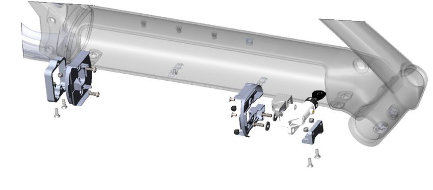
1                                                    2
Inspect the Knock Block components                   Install the Knock Block and Kiox
                                                     mount in the headset
              UPPER BEARING COVER
                                                      Description                              Part number
                KNOCK BLOCK CHIP
                                                      Knock Block 58-degree complete
                                                                                                 5252156
                                                      headset
                                                      Knock Block 58-degree upper
                                                                                                 5252157
                                                      assembly

                                                     KIOX CONTROLLER          KNOCK BLOCK CHIP BOLT
                                                                                       UPPER BEARING COVER
                                                     KIOX MOUNT

1.   Inspect the edges of these components for       KNOCK BLOCK CHIP
                                                                                                COMPRESSION
                                                                                                RING
     damage and wear.
     • Knock Block chip
     • Underside channel of the upper bearing                                                 UPPER BEARING

       cover
                                                                                                HEAD TUBE
     • Interlocking keys on top of the bearing
       cover (the keys that interface with the
       stem).
                                                                                           LOWER BEARING
2.   Replace damaged or worn components.
                                                                                                 CROWN RACE

                                                     1.    Connect the red controller cable (from the non-
                                                           driveside head tube access hole) to the Kiox
                                                           mount.

                                                     2.    Apply grease to the upper and lower head tube
                                                           bearing-bores.

                                                     3.    Apply grease to the inside bearing seats for
                                                           the compression ring and the crown race.

                                                     4.    Install the crown race, then the lower bearing
                                                           on the steerer tube.

                                                     5.    Insert the steerer tube into the bottom of the
                                                           head tube.

                                                     6.    Install the upper bearing and compression ring
                                                           onto the steerer tube.

                                                     7.    Use the Knock Block chip bolt to install the
                                                           Knock Block and Kiox display mount.

                                                     8.    Install the upper bearing cover.

                                                     9.    Install spacers as necessary.

                                                 1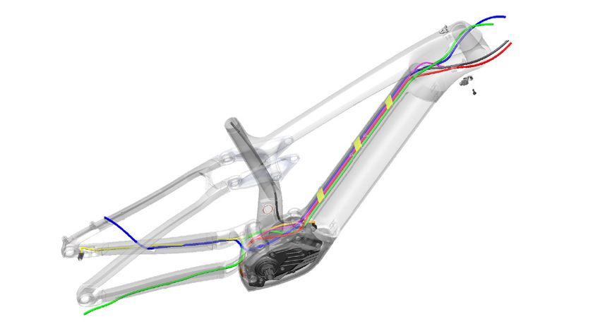
3                                                           4
Rear derailleur hanger                                       Frame guards
 Item                                                         Item
 number      Description                   Part number        number      Description                 Part number
             Derailleur hanger, bolt                             1        Upper down tube                556549
     1                                      W583423
             and 30mm washer                                              Down tube, medium and
For derailleur with Active Braking Pivot hardware kit,                    larger frames
                                                                  2                                     W590604
see page 13.                                                              Down tube, small frames
                                                                          (cut to fit)
                                                                  3       Chainstay                     W587594
                         1

                                                             1.       Use isopropyl alcohol to clean the frame
                                                                      surfaces that mate with the following guards:
                                                                CAUTION: Do not clean the entire frame with
                                                             isopropyl alcohol.

                                                             2.       Remove the protective covering for the
                                                                      adhesive.

                                                             3.       Attach the guards as shown.
  CAUTION: Do not apply grease between the
hanger and the bicycle frame.

   CAUTION: Do not apply grease to the hanger
bolt threads.

          NOTE    You must use a wrench that                                                                      1
     measures torque counterclockwise as well as                          3
     clockwise.

1.
                                                                                                           2
         Insert the hanger on the inside of the drive
         side chainstay.

2.       Install the washer on the derailleur hanger
         bolt.

3.       Insert the bolt into the frame.

4.       Make sure to have the hanger in the correct
         position as shown.

5.       Torque the hanger bolt to 25Nm (left-hand
         thread).
   CAUTION: Over tightening may cause the hanger
to break.
                                                         2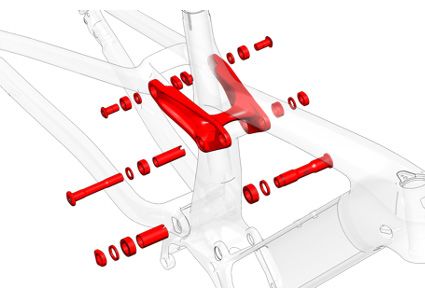
5     Cable routing

Cable                            Color                        1.     Zip tie the front light wire to the controller
Rear derailleur                  Green                               cable inside the frame above the RIB.
Rear brake                       Blue
Controller                       Red
                                                              2.     Route the shift housings and brake hoses.
Dropper post                     Black
Speed sensor                     Yellow
                                                                         NOTE   The plastic down tube guides have
Battery power                    Orange
                                                                   arrows which show the correct orientation.
Front light                      Magenta

                                                                                                    DROPPER POST
                                                                                                    (IF APPLICABLE)

                                                GUIDES                                              CONTROLLER

                                                                                               INTERNAL
                                                                                               GUIDE (2x)
                                                                                               (OPTIONAL)
                                                                                 FRONT LIGHT
                                                                                 WIRE
                    REAR BRAKE
     SPEED SENSOR

                                            BRAKE AND DERAILLEUR
                         REAR DERAILLEUR    CABLES CROSS OUTSIDE FRAME

                                                                          BATTERY POWER

                      CABLE ROUTING GUIDE

                                                         3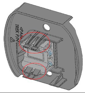
6     RIB system without alignment plate

Parts list
 Item number     Description                          Torque (Nm)     Part number   Quantity Kit part number
        1        Lower docking bracket                                    N/A           1
        2        Locknuts                                                 N/A           4
                                                                                                     580066
        3        T25 security screws                          5           N/A           4
       12        Upper docking bracket                                    N/A           1
        4        Connector plate                                          N/A           1
                                                                                                     579325
        8        Lock cover                                               N/A           1
        5        Button head cap screws                       5           N/A           2
        6        Countersunk bolts                            2           N/A           4
                                                                                                     579247
        9        Washers                                                  N/A           2
        7        Bumpers                                                579326          2
       10        Ejector assembly                                       579324          1             N/A
       11        Lock                                                  W562311          1             N/A

   1         2    3         4       5

                                          6   7   8       5       9                 3       2   12
                                                                      10 11

                                                  4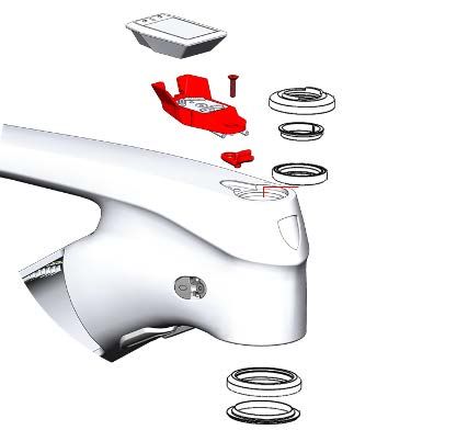
2020 & 2021 Rail service manual supplement

Remove the RIB mounting system                             8.      Remove the two button head screws (5) from
1.   Position the bike into a bike stand with the
                                                                   the lower docking (1).
     front end tipped down as shown below. This
     will prevent any loose hardware from falling
                                                           9.      Carefully extract the connector plate (4) and
                                                                   find the connection point for the battery plug.
     into the drive unit.

                                                           10. Disconnect this connection point from the
                                                                   battery plug.

                                                           11. Remove the two T25 security screws (3), the
                                                                   locknuts (2), and the lower docking bracket
                                                                   (1). Completely remove the lower docking sub-
                                                                   assembly from the bicycle.

                                                           12. If installing the new RIB system, remove the
                                                                   existing battery connection plug from the
                                                                   connector plate (4).

2.   Remove the RIB battery from the down tube.

3.   Note the cable routing paths. The cable routing
     will be the same for the installation.

4.   Remove the key from the battery lock.

5.   Remove the two bolts (6), the two bumpers
     (7), and the lock cover (8) from the upper
     docking bracket.

6.   Remove the two button head screws (5), the                       NOTE     To aid removal, you may need to
     washers (9), ejector assembly (10), and the
     lock (11).                                                 use a pair of cutters to clip off some or all of the
                                                                plastic hooks as shown. This plastic connector
7.   Remove the two T25 security screws (3) and
                                                                plate will not be reused with the new RIB system.
     the two locknuts (2), and the upper docking
     bracket (12).

                                                       5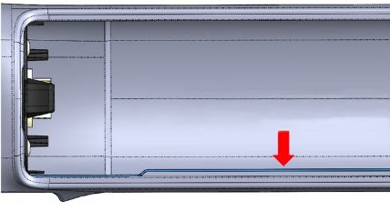
2020 & 2021 Rail service manual supplement

Install the RIB system                                    5.    Use the two button head screws (5) to install
1.    Position the bike into a bike stand with the
                                                                the connector plate (4).
      front end tipped down as shown below. This
      will prevent any loose hardware from falling
                                                          6.    Use the two T25 security screws (3) and the
                                                                two locknuts (2) to install the upper docking
      into the drive unit.
                                                                bracket (12).

                                                          7.    Use the two button head screws (5), the
                                                                washers (9) to install the lock assembly (10).

                                                          8.    Use the two bolts (6), the two bumpers (7) to
                                                                install the lock cover (8) to the upper frame
                                                                docking.

                                                          9.    Insert the key into the battery lock.

                                                          10. Install the RIB battery in the down tube.
2.    Check that the cables running along the
                                                          11. To test the connection, try to slide the battery
                                                                toward the head tube with the system powered
      bottom and/or top of the down tube are firmly
                                                                on.
      held in place and in the same routing paths
      from the removal.
                                                          12. Update the software per the manufacturer’s
3.    Use the two T25 security screws (3), the
                                                                process.
      locknuts (2) to install the lower docking
      bracket (1).                                        13. Perform the battery install and eject standard
                                                                operating procedure.
4.    Carefully connect the battery plug in the
      connector plate (4) to the battery connection
      on the drive unit.

                                                      6
7     RIB system with alignment plate

Parts list

 Item number   Description                                        Torque (Nm)   Part number        Quantity Kit part number
        1      Alignment plate                                                  W5252805              1
        2      Button head screws                                      2                              2
        4      Locknuts                                                                               2
        7      Button head cap screws                                  5                              2
                                                                                      N/A                       5257257
        8      Countersunk bolts                                       3                              2
      13       T25 security screws                                     5                              4
      11       Washers                                                                                2
        3      Lower docking bracket                                                                  1
                                                                                      N/A                       5256255
      12       Upper docking bracket                                                                  1
        5      Battery connection plug                                                N/A
        6      Lower battery-plug mounting                                            N/A             1
      14       Upper plastic lock cover                                               N/A             1         5256256
      15       Bumpers                                                               579326           2
        9      Plunger                                                               564539           1           N/A
      10       Lock assembly                                                        W591941           1           N/A

                                          3

                                              4
                 2                                 5      6

                                                                   7       8    9             10

                 1

                13                                                                        7
                                                                                               4

                                                                                     11       12

                                                                                               2

                                                                                              13

                                                  15 14

                                                              7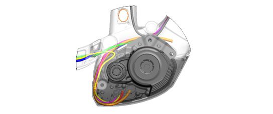
2020 & 2021 Rail service manual supplement

Remove the RIB system                                        5.   Remove the two bolts (8), the two bumpers
                                                                  (15), and the upper plastic lock cover (14).
          NOTE      This can be done without removing
     the drive unit from the bike frame.                     6.   Remove the plunger (9) and the lock
                                                                  assembly (10).

          NOTE    Save all fasteners, bumpers, and           7.   Remove the two button head screws (7) and
     lock assembly for installation.                              the washers (11) from the upper docking
                                                                  bracket (12).
1.     Position the bike into a bike stand with the
                                                             8.   Remove two button head screws (7) and the
       front end tipped down as shown below. This
       will prevent any loose hardware from falling               lower battery-plug mounting cover (6) with the
       into the drive unit.                                       battery plug.

                                                             9.   Thread the battery plug connection through the
                                                                  lower metal docking bracket (3) and remove
                                                                  the plug connection.

                                                             10. Remove the four security screws (13) and the
                                                                  locknuts (4) to remove the alignment plate
                                                                  (1) with the upper (12) and lower (3) docking
                                                                  brackets as a sub-assembly.

                                                             11. Remove the two button head screws (2), and
                                                                  the upper (12) and lower (3) docking brackets
                                                                  from the alignment plate (1).
2.     Remove the RIB battery from the down tube.

3.     Note the cable routing paths. The cable routing
       will be the same for the installation.

4.     Remove the key from the battery lock.

                                                         8
2020 & 2021 Rail service manual supplement
Install the RIB system 3. Position the lower docking bracket (3) on
1. Position the bike into a bike stand with the
the alignment plate as show below. Use one
button head screw (2) to attach the bracket to
front end tipped down as shown below. This
the plate. Torque the screw to 3Nm.
will prevent any loose hardware from falling
into the drive unit.
4. Use one button head screw (2) to attach the
2. Install the battery connection plug into the
upper docking bracket as shown below. Torque
the screw to 3Nm.
lower battery-plug mounting cover (6).
BATTERY CONNECTION
PLUG
UPPER BRACKET
NOTE Make sure the cables running along
5. Place the alignment plate into the opening in
the frame.
the bottom and/or top of the down tube are firmly
held in place.
NOTE The underside of the alignment
plate has a directional arrow to show which end
points to the head tube.
6. Grease the heads of the four security
screws (13).
92020 & 2021 Rail service manual supplement
7. Use these four security screws (13) and the 10. Reuse two button head screws (7) to install
locknuts (4) to attach the sub-assembly. the lower battery plug mounting cover (6) with
the battery plug.
Do not fully tighten the screws at this time.
Do not fully tighten the screws at this time.
11. Use the two washers (11) and button head
screws (7) to install the lock assembly (10) to
the upper docking bracket (12).
LOWER BRACKET UPPER BRACKET
IMPORTANT: Make sure you do not crush or squeeze
any cables running along the base of the down tube.
Cable routing should match the original cable routing
prior to this modification.
8. Apply threadlocker 242 (or similar) into the 12. Tighten the screws until the washers (11)
threaded holes in the dock mounts. Wipe away slightly contact the lock core and you can still
excess threadlocker to minimize the chance slide the lock core against the docking bracket
of contact with the lower battery mounting (12) for adjustment.
cover (6).
13. Use the two bolts (8) and the two bumpers
9. At the lower bracket, thread the battery (15) to install the upper lock cover (14).
plug connection through the lower docking Tighten the bolts to 2Nm.
bracket (3).
14. Push the upper lock cover (14) toward the
head tube until the small plastic tab is just
touching the edge of the frame cutout. Do not
apply excess pressure.
102020 & 2021 Rail service manual supplement
15. Check to make sure the lock is centered (as 19. Slide the upper docking (12) toward the drive
much as possible) in the bicycle frame hole. side as far as it can go, and tighten the two
security screws (13) to 5Nm.
LOCK
ASSEMBLY
BIKE FRAME
16. Once the lock is centered, snug – but do not
fully tighten – the two security screws (13) in
the bicycle frame.
20. Install the RIB battery and observe if the
battery appears to install and eject properly.
Because you have adjusted the dockings to
their maximum driveside adjustment, the gap
between battery and frame may be greater
than desired. To adjust placement follow
steps 20–22. If you are satisfied, skip to 24.
21. Loosen the two button head screws (7) on
each docking and adjust the driveside/non-
driveside position of the dockings until you
have a 2–3mm frame gap. Then torque the two
upper and the two lower button head screws
17. Ensure the middle of the alignment plate is (7) to 5Nm.
not bowed upward or downward and is snug.
Do not fully tighten the two button head 22. You may see that the gaps at the upper and
screws (7). lower end of the battery are not symmetrical.
This is okay from a functional standpoint.
But you may, with caution, use the security
screws (13) to position the docking assembly
farther down toward the motor. However, it is
recommended that the best visual appearance
be maintained at the upper edge of the
battery, versus the lower.
18. Slide the lower docking (3) toward the drive
side as far as it can go, and tighten the two
security screws (13) to 5Nm.
112020 & 2021 Rail service manual supplement
23. After adjustments are complete, remove the
battery and inspect the alignment plate.
PLATE SHOULD BE STRAIGHT AND FLAT AFTER ALL
FASTENERS ARE TIGHTENED.
IMPORTANT: Make sure the alignment plate is
straight and not bowed up or down.
24. Re-install the battery.
25. To test the connection, try to slide the
battery toward the head tube with the system
powered on.
26. Update the software per the manufacturer’s
process.
27. Perform the battery install and eject standard
operating procedure.
128 Bosch drive unit removal/installation 9 Suspension hardware
See the appropriate Bosch removal and installation 23 1 17Nm
instructions for your drive unit.
4
2
3 76
9
8
1 67
17Nm 1211 14
30Nm
13
1112
5
10
ROCKER PIVOT AND MAIN PIVOT AXLE
Item Part
number Description number Quantity
1 Mino link bolt W579296 1
2 Mino link spacer W529969 1
3 Mino link bearing W529224 1
4 Mino link nut W529223 1
5 Rocker pivot axle W535469 1
Rocker pivot
6 W290057 1
spacer
Rocker pivot
7 W586543 1
bearing
Rocker pivot
8 W310155 1
bearing sleeve
9 Rocker pivot nut W311582 1
Rocker pivot kit – one each
of pivot axle, sleeve and
599910 1
nut, two bearings and two
spacers
10 Main pivot nut W584134 1
11 Main pivot spacer W440921 1
12 Main pivot bearing W302025 1
13 Main pivot sleeve Kit only
14 Main pivot axle Kit only
Main pivot point hardware
kit – one each of pivot axle,
599909 1
sleeve and nut, two spacers
and two bearings.
132020 & 2021 Rail service manual supplement
17 15
16 17Nm
16 17
19 10Nm
16
17 17 16
17 15
18 17Nm
17
17Nm 15 18 19 10Nm
18 19 17 18
17
15 17Nm 20
THRU-SHAFT SHOCK HARDWARE STANDARD SHOCK HARDWARE
Item Part Item Part
number Description number Quantity number Description number Quantity
Thru shaft shock Upper shock
15 W547868 1 16 W529969 1
bolt spacer
Upper shock Shock pivot
16 W529969 1 17 W293466 1
spacer bearing
Shock pivot Lower shock
17 W293466 1 18 W536414 1
bearing spacer
Lower shock Upper shock axle
18 W536414 1 19 599898 1
spacer and end cap kit
Lower shock axle
20 599900 1
and end cap kit
1410 11
Dropout hardware Specifications
52mm “Boost” with
Chainline:
26 offset chain ring
22 Maximum chain ring: 34T (1x only)
23
24 Maximum tire size: 29x2.60
23 170mm – axle to
25 Fork maximum:
crown: 580mm
Frame & fork travel: 160mm
22 Headset lower stack height: 1mm
Shock eye-to-eye length: 230mm
Shock stroke length: 57.5mm
ACTIVE BRAKING PIVOT DROPOUT AND SKEWER Upper shock mount width: 54mm
Lower shock mount width: 40mm
Item Part
number Description number Quantity Shock axle/bolt diameter: 10mm
22 Bearing W583424 1
Spacer (carbon 1
23 W583422
frames only)
24 Axle guide W583419 1
25 Axle nut W583420 1
26 Rear skewer W583470 1
Active Braking Pivot 599911 1
universal hardware kit –
universal derailleur hanger
with bolt and washer,
one axle guide, one axle
nut, two spacers and two
bearings.
15You can also read