VERMEIREN - Illico INSTALLATION MANUAL
←
→
Page content transcription
If your browser does not render page correctly, please read the page content below
VERMEIREN

Illico   INSTALLATION MANUAL
EN
                                                                                                                                     Illico
                                                                                                                                 2021-02
                                                                                                                                 Contents

Contents
                                                                                                                                              NL

   Contents ..................................................................................................................... 1
   Preface........................................................................................................................ 2
   1           This product .................................................................................................. 3
   2           Scope of delivery .......................................................................................... 4
   3           Transport ....................................................................................................... 5
       3.1     Dimensions ..................................................................................................... 5
       3.2     Loading the transport trolley ........................................................................... 6
       3.3     Stacking beds for transport or storage ............................................................ 8
   4           Assembly and disassembly ....................................................................... 10
       4.1     Tools ............................................................................................................. 10
       4.2     Control box connections ............................................................................... 10
       4.3     Assembly ...................................................................................................... 11
       4.4     Disassembly ................................................................................................. 15
       4.5     Installing motor.............................................................................................. 18
       4.6     Installing trapeze handle ............................................................................... 19
       4.7     Installing side rails......................................................................................... 19
       4.8     Installing the width extension kit.................................................................... 21
       4.9     Installing the length extension kit .................................................................. 21

                                                      Installation manual
                                                               -1-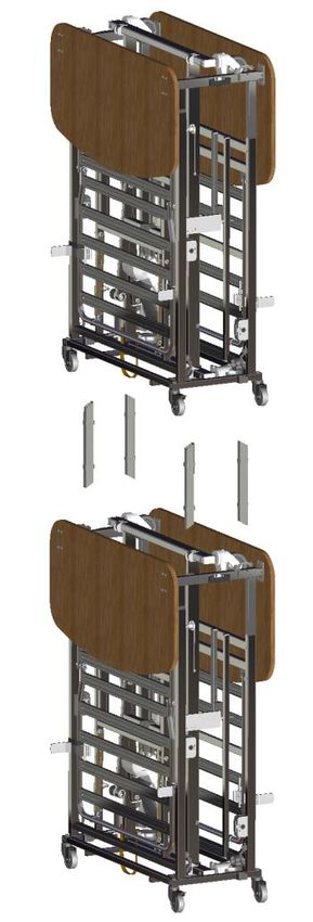
EN
                                                                                                     Illico
                                                                                                  2021-02
                                                                                                  Preface
NL   Preface
     To support you on the installation and repairs of this nursing bed, we provide you with this
     installation manual. Please read it carefully. If you still have questions after reading this manual,
     do not hesitate to contact Vermeiren.
     The information in this manual applies to the following bed(s):
         • Illico

     Important note
     Pictures of the product are used to clarify the instructions. Details of the shown product may
     deviate from your product.

     Information available
     On our website http://www.vermeiren.com/ you will always find the most recent version of
     following information. Please consult this website regularly for possible updates.

     Visually impaired people can download the electronic version of this manual and have it read out
     by means of a text-to-speech software application.

               •   Instruction manual
                   For user and specialist dealer

               •   Installation manual (instructions for assembly and disassembly)
                   For specialist dealer

               •   Mounting instruction Knee-bend system
                   For specialist dealer

               •   Drawings of (spare) parts
                   For specialist dealer

               •   Service manual (beds)
                   For specialist dealer

               •   EC declaration of conformity

                                               Installation manual
                                                        -2-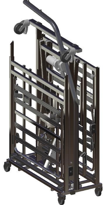
EN
Illico
2021-02
This product
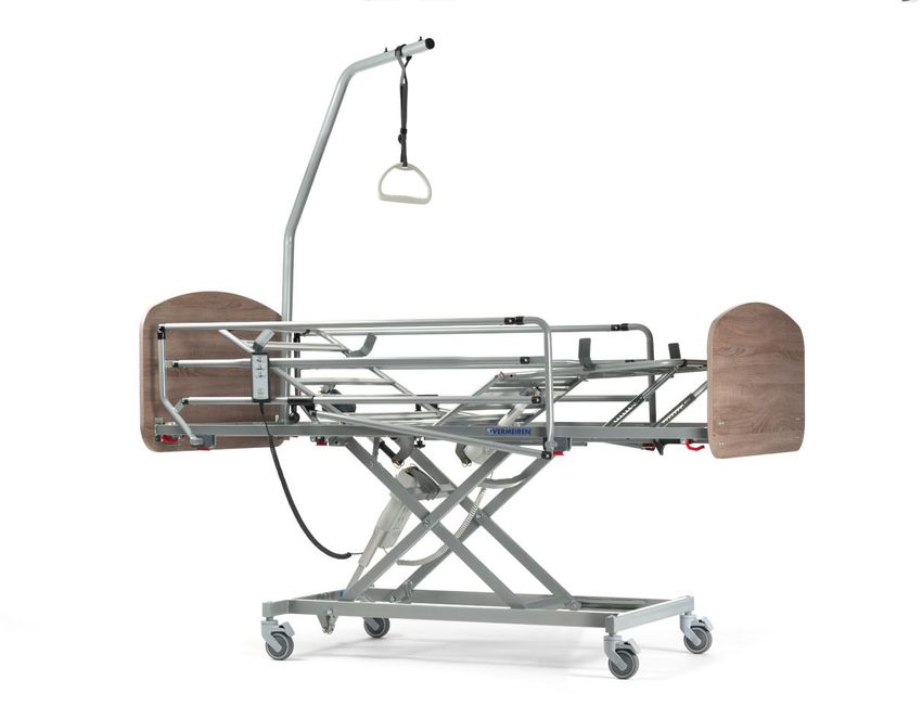
1 This product
NL
Read the complete user manual before operating the bed.
19
2
11 12
1 5 3 4
16 8
6
9
7
10
29
Important parts
1. Headboard 11. Location of identification plate
2. Lifting pole / Trapeze handle (on bed frame, at head end)
3. Side rail, foldable 12. Strap
4. Footboard 16. Mattress support, comprising
5. Handset o lower leg section
6. Motor of head section o upper leg section
7. Motor of mattress support o head section
8. Motor of knee bend (optional) 19. Mattress retainer
9. Undercarriage 29. Power cable support
10. Caster wheel with brake (for strain relief unit)
Installation manual
-3-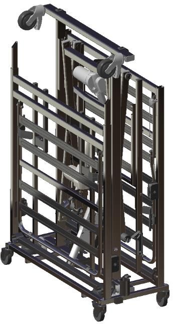
EN
Illico
2021-02
Scope of delivery
NL 2 Scope of delivery
Risk of unsafe settings
• The Illico bed has two configuration options: one with a complete metal mattress support, and
one with a mattress frame with plastic supports.
• The motor to operate the knee bend is optional.
The following components are part of the delivery:
• Undercarriage driven by motor Linak LA40, with control box Linak CA40 and control-box
opener
• Mattress support, with adjustable head section, upper leg and lower leg section
(with rastomat)
• Head section driven by motor Linak LA27
• Headboard
• Footboard
• Foldable side rail (L&R)
• Handset with locking key; Linak HL7X045-01
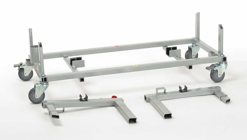
• Transport trolley (Lower frame and upper connections L&R)
• Stacking connectors (4x)
• User manual
• Options and/or accessories
Before use, check if everything is included and that no products are damaged.
Installation manual
-4-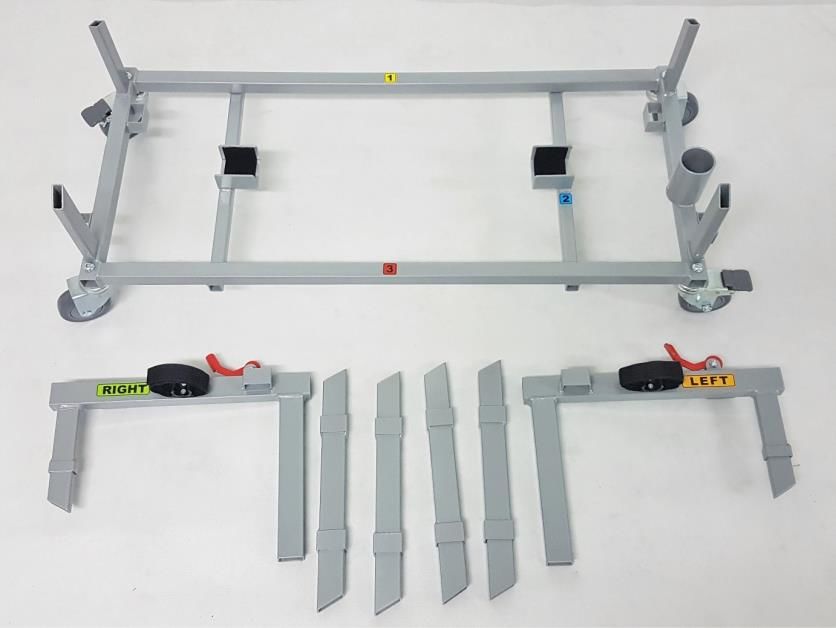
EN
                                                                                                                Illico
                                                                                                             2021-02
                                                                                                            Transport

3       Transport
                                                                                                                         NL
            CAUTION    Risk of injuries or damage
Attach all bed parts and transport trolley firmly to the vehicle, to prevent them from moving during
transport.

3.1         Dimensions
            CAUTION    Risk of injuries or damage
For transport and storage, you should take the following dimensions into account.

      Other bed dimensions can be found in the instruction manual.

Table 1 Transport trolley and bed dimensions
Description                                        Dimension                            Value
Transport trolley, loaded with                                                   With one bed; without
                                                 Specification
bed                                                                  side rails, lifting pole, stacking connectors
                                                   Total mass                          95,9 kg
                                                    LxWxH                      1030 x 425 x 1400 mm
Two transport trolleys stacked                                    With two beds, all 4 stacking connectors; without
                                                 Specification
on each other                                                                 side rails, lifting poles
                                                   Total mass                         194,2 kg
                                                    LxWxH                      1030 x 425 x 2800 mm
Transport trolley                                Specification                With upper connections
                                                   Total mass                          10,4 kg
                                                    LxWxH
                                                                               1020 x 420 x 275 mm
                                                 Lower frame:
                                                   LxWxH
                                                                                 362 x 50 x 265 mm
                                   Upper connection left/right:
Stacking connector (4x)                          Specification                     Each connector
                                                         Mass                          0,60 kg
                                                    LxWxH                        40 x 25 x 340 mm
Side rail                                        Specification                       Left or right
                                                         Mass                           6,6 kg
                                                    LxWxH                      1450 x 100 x 470 mm
Lifting pole                                     Specification                    With trapeze bar
                                                         Mass                           5,9 kg
                                                    LxWxH                       855 x 40 x 1440 mm
Undercarriage, with control box,
                                                         Mass                          30,4 kg
power cable and handset
Head section frame, with head
                                                         Mass                          20,2 kg
support, motor
Foot section frame, with leg
                                                         Mass                          21,3 kg
support, motor
Headboard                                                Mass                           7,3 kg
Footboard                                                Mass                           6,2 kg

                                               Installation manual
                                                        -5-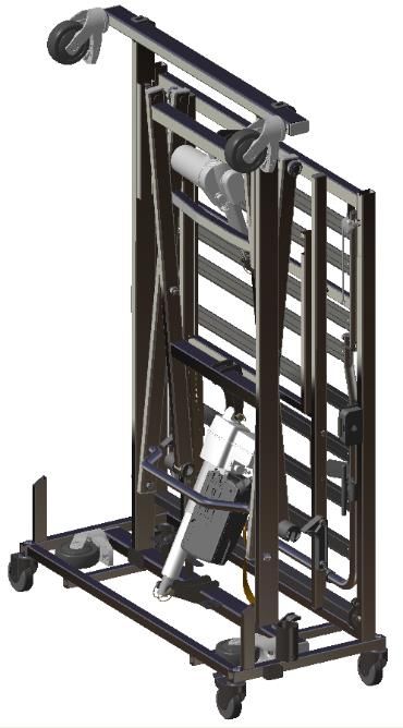
EN
                                                                                                     Illico
                                                                                                  2021-02
                                                                                                 Transport
NL   3.2       Loading the transport trolley
           •   Follow the instructions below to correctly position all bed parts on the transport trolley.
           •   Use the sticker number on the bed part to locate the position on the trolley. This number
               can be found in the instruction between two arrowheads “>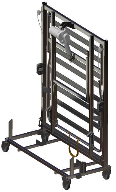
EN
                                                                                                Illico
                                                                                             2021-02
                                                                                            Transport
                                                                                                         NL

[1]                                 [2]                                [3]

Place the lower frame of >Insert at No. 1<                >Insert at No. 2<
transport trolley on level Leg section, with strap at the Undercarriage with motor on
ground with brakes applied. bottom, motor inwards.        bottom side.
                                                          Lower castor wheels turned
                                                          inwards and locked.
                                                          Upper castor wheels straight and
                                                          pointing outwards.

                                                                   b
                                                                                      e     c

[4]                                 [5]                                [6]

>Insert at No. 3<             Lifting    pole     in      between Trolley upper-left and upper-right
Head section with head end undercarriage and head section, in connectors (b+c); on tube ends of
at the bottom, motor inwards. the pole socket of the trolley.     head and leg section.
                                                                  Make sure that both plastic
                                                                  mounts (e) point outwards.

                                          Installation manual
                                                   -7-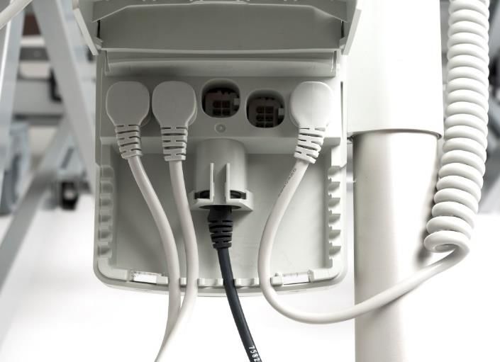
EN
Illico
2021-02
Transport
NL
h
g e
f
[7] [8] [9]
Footboard in trolley upper After folding, each metal side bar is mounted vertically:
part L&R. Lock the footboard • with its lower shaft in rotation point (f) of leg section;
with red lever (g). • with top part in plastic mount (e) on upper connector.
Headboard on trolley upper Use the Velcro straps to connect:
part L&R. Lock with red lever • top part in plastic mount (e) on upper connector;
(h). • the head section support to head section frame;
• the leg section support to leg section frame.
CAUTION Risk of injuries or damage
Check if all parts are well secured.
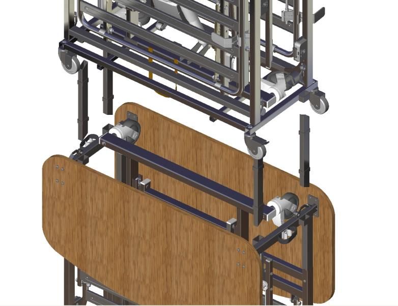
3.3 Stacking beds for transport or storage
WARNING Risk of severe injuries and damage
• Lifting of (stacked) beds may only be done by authorised and trained personnel and with
suitable lifting equipment!
• Transportation of stacked beds is only allowed by trained and authorized personnel according
to the instructions in this manual, the instructions of the vehicle and the local transportation
regulations.
• Stacked beds should be moved on firm, flat and level surfaces, to minimize the risk of tipping
over.
• Always use the stacking connectors (i) to keep two stacked transport trolleys in line.
CAUTION Risk of injuries and damage
• Two beds can only be stacked without side rails and without lifting pole.
Installation manual
-8-EN
Illico
2021-02
Transport
NL
l
i2
k i1
l
k
k
• Put a stacking connector (i) in the strike hole (k) at each of the upper connectors (4x):
o on the inside of the frame tube (i1),
o on the outside (i2).
• Place the trolley with the second bed on top of the first by means of lifting equipment.
Make sure that the stacking connectors slide in the 4 strike holes (l) of the lower frame of the second
trolley.
• Ensure that the beds are well connected.
CAUTION Risk of injuries or damage
Make sure that all parts are well secured.
Installation manual
-9-EN
Illico
2021-02
Assembly and disassembly
NL 4 Assembly and disassembly
CAUTION Risk of injuries or damage
• The bed needs to be (dis)assembled by a specialist dealer according to the instructions in this
chapter.
• Only use parts described in this manual.
• Prevent bystanders from accessing the (dis)assembling area.
• Keep the (dis)assembling area clean and tidy, to prevent falling.
• Collect all small parts in a box or bag.
• While (dis)assembling and operating the bed, make sure no objects or body parts get caught
between parts. In particular, pay attention to the position of the cables.
4.1 Tools
To (dis)assemble the bed, no special tools are needed, except a tool to open
the control box, see picture. This control box opener is part of the delivery and
is attached in a recess at the back of the control box.
Control-box opener
4.2 Control box connections
Detail information on Linak control box CA40 can be found on website: www.linak.com
Connect all cables according to following list, Figure 4 and Figure 5:
(a) Powersupply cable > In external socket
(b) Motor of undercarriage > In socket no. 1
(c) Motor of head section > In socket no. 2
(d) Motor of leg section (optional) > In socket no. 4
(e) Handset > In protruding socket
a
Power supply cable connection
Installation manual
- 10 -EN
Illico
2021-02
Assembly and disassembly
NL
b
d
c
e
Motor and handset connections
• Make sure that each cable lies in a notch of the housing before closing the cover of the
control box.
• Close the cover after connecting the cables.
4.3 Assembly
B
[1] [2]
• Place the undercarriage with the four wheels • Open the control box with the control-box
on a flat and level floor. opener (see §4.1), by pressing the two
• Apply the brake on the four castor wheels locking clips simultaneously.
(position B). • Connect the handset and power supply
cable, if not connected yet, see §4.2.
• Unwind the power supply cable from the
cable holder on the undercarriage frame.
• Plug the power supply cable in the 230V
socket.
Installation manual
- 11 -EN
Illico
2021-02
Assembly and disassembly
NL
C 18
19
[3] [4]
• Use the handset to raise the cross of the • Make sure that the cable of the handset is on
undercarriage to its assembly position C. the side of the undercarriage.
• Take the leg section (with strap) from the
At position C, the roller shaft of the cross transport trolley, place it on the roller wheels
is in line with the marking on the base (18) and roll it to the undercarriage, on the
frame. side with rollers (19), see next picture.
20
22
19
21 21
[5] [6]
• While resting on the roller wheels, lay the leg • Take the head section and roll it to the
section with the frame cut-out (20) over the undercarriage, on the side of the control box.
rollers (19) of the undercarriage. • While resting on the roller wheels, lay the
If the rollers (19) do not fall in the frame head section on supports (21) of the
cut-outs (20) of the leg section, adjust the undercarriage, see previous picture.
height of the cross according to step 3 If the rotation pins of connection (22) do
and try again. not fit in the supports (21), adjust the
height of the cross according to step 3
• If applicable, connect the motor of the leg
and try again.
section to the control box, see §4.2.
Installation manual
- 12 -EN
Illico
2021-02
Assembly and disassembly
NL
32
31
D
[7] [8]
• Lift the head section end and place it • Lift the leg section end a bit and move it
horizontally. Safety guide (31) will get caught towards the head section.
by locking pin (32) of the undercarriage
preventing the head section from lowering CAUTION Risk of damage
again. If the leg section has a motor, make sure that it
• Connect the motor of the head section, see does not hit the bend frame tube of the
§4.2. undercarriage at point D. For this reason, keep
the leg rest end in low position until the motor
has passed the bend frame tube.
23
[9] [10]
• Slide the leg section frame tubes over the • Slide the leg section further until the outer
protruding inner tubes of the head section. frame tubes touch.
• Turn star knob (23) in the hole of the tube and
tighten it. Repeat this on the other side of the
bed.
Installation manual
- 13 -EN
Illico
2021-02
Assembly and disassembly
NL
24
[11] [12]
• Slide the two headboard tubes in the open • Place the lifting pole in one of the two pole
tube ends of the head section. sockets at the head-end side.
• When the headboard is in place, it can easily
be locked by pressing both red levers (24) up.
If this is not possible, slide the headboard
backwards/forwards until the lever falls in the
locking hole.
• Repeat this step for the footboard.
[13]
• Mount the metal, wooden or split side rails according to the instructions in §4.7.
Installation manual
- 14 -EN
Illico
2021-02
Assembly and disassembly
NL
A
B
[14] [15]
• Finally, make sure that all assembled parts are • Release the brakes of the castor wheels
locked in place. (position A).
• Move the bed in place according to the
CAUTION Risk of damage description in the instruction manual.
Before operating the handset, make sure that • Apply the brakes (position B).
cables won’t get crushed by moving parts. The bed is now ready for use.
• Check the operation of the bed by using the
handset, see instruction manual of the bed.
4.4 Disassembly
B
[1] [2]
• Apply the brakes on the castor wheels (position CAUTION Risk of damage
B).
Before operating the handset, make sure that
cables won’t get crushed by moving parts.
• Use the handset to lower the head and leg
section until they are flat.
Installation manual
- 15 -EN
Illico
2021-02
Assembly and disassembly
NL
[3]
• Remove the metal, wooden or split side rails according to the instructions in §4.7.
24
[4] [5]
• Remove the lifting pole by lifting it from its • Unlock the footboard on left and right side by
support. pulling the red levers (24) down.
• Pull the footboard back to remove it from the
frame of the mattress support.
• Repeat this for the headboard.
C
23
[6] [7]
• Use the handset to raise the cross of the • Loosen star knob (23) and remove it from the
undercarriage to its assembly position C. frame tube.
• Repeat this on the other side of the mattress
support.
Installation manual
- 16 -EN
Illico
2021-02
Assembly and disassembly
NL
18
[8] [9]
• Pull the leg section back until it is free from the • Lower the leg section end and place it on the
head section. roller wheels (18).
32
31
[10] [11]
CAUTION Risk of entrapment • Open the control box with the control-box
opener (see §4.1), by pressing the two locking
Prevent fingers getting entrapped by the frame-
clips simultaneously.
cross locking system.
• Unplug the motor cables of head and leg
• Push and hold the head section a bit down at section, see §4.2.
the front, with one hand. Push with your other
hand the support with locking pin (32) aside to
let the guide (31) pass the pin. The location to
push is marked with a green dot.
• Release the locking pin when the guide has
passed.
• Lower the head-section end and place it on its
roller wheels.
Installation manual
- 17 -EN
Illico
2021-02
Assembly and disassembly
NL
[12] [13]
• Lift and turn the head section on the roller • Use the handset to fold the undercarriage
wheels. completely.
• Remove the head section with motor and • Unplug handset cable, see §4.2.
cable. • Close the control box.
• Repeat this for the leg section. • Wind the power-supply cable on the cable
holder of the undercarriage.
• Store all components on the transport trolley,
see chapter 3.
4.5 Installing motor
[1] [2] 33
• Disassemble the bed according to the • Install the motor of the leg section according
instructions in §4.4, up to step [12], to create to the mounting instructions included in the
some space to work. box of the actuator.
• Use the handset to raise the frame cross. • Assemble the bed according to the
instructions in §4.3.
Installation manual
- 18 -EN
Illico
2021-02
Assembly and disassembly
4.6 Installing trapeze handle
NL
37
2
34
35
2. Lifting pole
36 34. Lifting strap
35. Belt
36. Buckle
37. Anti-slip holder (elastic)
• Place lifting strap (34) with anti-slip holder (37) on lifting pole (2).
• Adjust the length of belt (35) by sliding the belt through the buckle (36).
• Put the remaining belt end through the belt loop.
Make sure that the belt is well tightened.
4.7 Installing side rails
4.7.1 Metal side rails
Assembly
1. Take the left or right side-rail and hold it next to the
frame of the mattress support. Make sure that the 39
canted corner is located on the headboard-side.
2. Press and hold red lever (26), while inserting the shaft
of the side rail in block (39) (rotation point).
3. When both shafts are inserted, check the locking of
the side rail by pushing and pulling the side rail. 26
4. Repeat this for the second side rail.
Disassembly
1. Press one of the red levers (26) to release the lock of
side rail and pull the side rail a bit backward.
2. Repeat this at both red levers until the side rail is
released.
3. Repeat this for the second side rail.
4.7.2 Wooden side rails
Assembly
1. Insert the short bolt rails (1) on the right and left in the upper wooden slat.
2. Insert the long bolt rails (2) on the right and left in the lower wooden slat.
3. Insert the long bolt rails (2) with the wooden slat in the sliding rail (4) of the head and feet
panel and secure them by inserting the long bolt rails until the upper end clicks into place.
4. On one side, release the rail again by pressing the position locking button (5) and pulling the
upper wooden slat gently upwards.
5. Let the bolt rails (2) fall from the sliding rail until the tip of the rail is just barely in the guide.
The short bolt rail (1) with wooden slat can now be inserted between the walls of the long bolt
Installation manual
- 19 -EN
Illico
2021-02
Assembly and disassembly
NL rails. The entire bolt rail system (1) + (2) can be placed in the relevant sliding rail (4) by pulling
upwards while grasping only the upper wooden slat and then locking the structure into
position.
6. Insert the locknuts (6) and tighten them manually.
7. Repeat for the other side rails.
1 = Short bolt rails
2 = Long bolt rails
3 = Wood slats (2 pieces each side)
4 = Sliding rail
5 = Position locking button
6 = Locknut
Disassembly
1. Loosen and remove the locknuts (6).
2. Release the side rails by pressing the position locking button (5) and gently let them slide out
of the sliding rails (4).
4.7.3 Split side rails
Assembly
1. Take one of the split side rails.
Mind the difference between head-end or foot-end 40
rails (head-end rails are shorter than foot-end
rails).
2. Place the split side rail attachments over the mattress
frame support.
3. Firmly tighten the two screws on the bottom of each
attachment (40).
4. Repeat for all other split side rails.
5. Make sure that all side rails are firmly attached into
place.
Disassembly
1. Loosen and remove the screws (40) on the bottom of each split side rail attachment.
2. Carefully take off the split side rails from the bed frame.
Installation manual
- 20 -EN
Illico
2021-02
Assembly and disassembly
4.8 Installing the width extension kit
NL
• The width extension kit is not compatible with the split side rails.
• Make sure not to switch the headside and footside bars (head-end bars are shorter than
foot-end bars).
1. Attach the width extension bars to the bed frame by placing the U-shaped brackets (38) over
the mattress support bar (39). The horizontal bracket (40) should be placed under the
bedframe tubes of the seat section.
2. To fix the bars into place, mount the separate brackets (41) below the bedframe bar and width
extension bar, near the headboard/footboard, and tighten the screws.
3. Replace the standard mattress retainers with elongated mattress retainers (release/mount by
removing/inserting the rod (42) under the slats of the slatted frame).
4. Replace the standard mattress with a wider one.
38
39
40
41
42
4.9 Installing the length extension kit
1. Unlock the footboard by the red levers and
remove the footboard (see §4.4).
2. Insert the length extension frame and lock
into place with the red levers of the bed
frame (43).
3. Turn star knob (44) in the hole of the tube
and tighten it.
4. Insert the footboard into the length
extension frame and lock into place with the
red levers of the extension frame (45).
5. Replace the standard mattress with a
longer one. 43 45
44
Installation manual
- 21 -Vermeiren GROUP
Vermeirenplein 1 / 15
2920 Kalmthout
BE
Installation manual - Illico_EN_A5_2021-02_D
website: www.vermeiren.com
Instructions for specialist dealer R.E.: Vermeiren GROUP, Vermeirenplein 1/15 - 2920 Kalmthout – Belgium
This instruction manual is part and parcel of the product and must accompany
every product sold.
Version: D, 2021-02 Basic UDI: 5415174 181210Illico RN
All rights reserved, including translation.
No part of this manual may be reproduced in any form what so ever (print,
photocopy, microfilm or any other process) without written permission of the
publisher, or processed, duplicated or distributed by using electronic systems.
© Vermeiren Group 2021You can also read