E-Socket Quick installation guide Guide d'installation rapide

Page created by Gary Woods
 
CONTINUE READING
E-Socket Quick installation guide Guide d'installation rapide
–
E-Socket
Quick installation guide
Guide d’installation rapide
E-Socket Quick installation guide Guide d'installation rapide
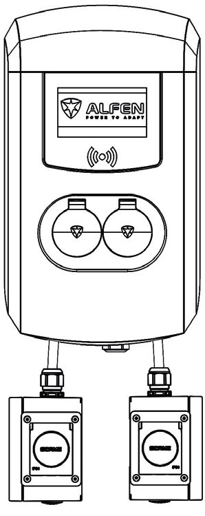
TABLE OF CONTENTS/ TABLE DES MATIÈRES

Quick installation guide 				  3
Guide d’installation rapide				15
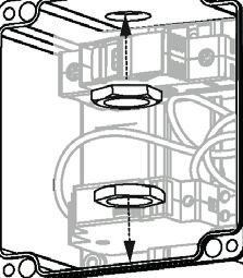
E-Socket Quick installation guide Guide d'installation rapide
TABLE OF CONTENTS

Package contents						4

Connecting the E-socket					5

Assembling the E-Socket for
mounting on the right side					         6

Assembling the E-Socket for
mounting on the left side					          8

Installing the E-Socket on the
Eve Single Pro-line FR					             10

Installing the E-Socket on the
Eve Double Pro-line FR					             11

Appendix: Single line diagram       			23

                                3
E-Socket Quick installation guide Guide d'installation rapide
en
      This document contains installation instructions       Package contents
      for the E-Socket. Please always refer to our
      website for the most up-to-date and complete
      manual for the product.www.alfen.com/en/
      downloads.
                                                                4     M4x16 Anti-theft screw
      The installation must comply with standards
      and (local) regulations and must only be carried
      out by a qualified technician.

      The electrical system must be disconnected
      from every power source before performing any
      installation or maintenance work!

      This manual describes the installation of the E-          1       Junction box with
      Socket for both the Eve Double Pro-line FR and                      E-Socket plug
      the Eve Single Pro-line FR simultaneously.

Conditions of use
                                   -25 °C /                     2     M25x1.5 Cable gland
Operating temperature
                                   +40 °C                              M25x1.5 Locknut
Relative humidity                  5% / 95%
Electrical safety class            I
Protection rating                  IP54
                                                                1          Filler plug
                                                                        M25x1.5 Locknut

                                                                1          Power cord

                                                                1     Wall mounting bracket

                                                         4
Quick start guide                                       E-Socket
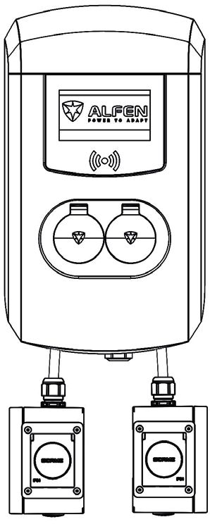
Connecting the E-Socket to the                                    Connecting the E-Socket to the
Eve Double Pro-line FR                                            Eve Single Pro-line FR
                                                       1                                                                    2

                                                                              Left                         Right
             Left                        Right

The E-Socket on the Eve Double Pro-line FR                        The E-Socket on the Eve Single Pro-line FR
        A total of two E-Sockets can be installed on the                  A total of one E-Socket can be installed on the
        Eve Double Pro-line FR.                                           Eve Single Pro-line FR.

1   Determine the position of the E-Socket(s):                    1   The E-Socket can only be installed on the right
    •   Left and/or                                                   side of the Eve Single Pro-line FR.
    •   Right.
                                                                          The E-Socket cannot be mounted on the Eve
        The E-Socket cannot be mounted on the Eve                         Single Pro-line FR. Do not leave the E-Socket
        Double Pro-line FR. Do not leave the E-Socket                     hanging. Use the proper mounting kit for
        hanging. Use the proper mounting kit for                          installation:
        installation:                                                 •   Wall mounting: The wall bracket (included in
    •   Wall mounting: The wall mounting bracket                          package).
        (included in package).                                        •   Mounting pole: The Pole mounting bracket E-
    •   Installation on Mounting pole (934459002): The                    Socket (803873063-ICU).
        cable cover E-Socket (803873064-ICU).
                                                                  2   Example of the assembled E-Socket:
2   Example of the assembled E-Socket:                                •   Right side assembly.
    •   Right side assembly.
    •   Left side assembly.                                       3   Preparing for assembling
                                                                      •   Right side assembly: Orientate the junction box
3   Preparing for assembling                                              with the opening facing to the right.
    •   Right side assembly: Orientate the junction box
        with the opening facing to the right.
    •   Left side assembly: Orientate the junction box with
        the opening facing left.

                                                              5
en

Hinge
socket on                        1       Assembling the E-Socket for
topside
                   Relay
                                         mounting on the right side
                                         Preparing for installation
                                         1   Orientate the Junction box with the opening
                   Fuse holder               facing to the right.
 Facing left

                                                 Do not damage the power cables and wires.

                                         2   Insert the cable gland at the top of the junction
                           2     3           box and fit the locknut. Do not tighten.

                                         3   Insert the filler plug at the bottom of the
               2                             junction box and fit and tighten the locknut.

                                         4   Feed the power cord end with the cable shoes
                                             and the flat cable lugs through the cable gland.
                                             •   Tighten the gland.

                                                 Ensure the cable is clamped firmly in the gland.
                                                 Only then will the IP54 sealing be effective.

               3                                 Take care not to damage the cables; keep them
                                                 clear of the locking mechanism so they do not
                                                 obstruct it.

                                 4

                                     6
Quick start guide                                       E-Socket
                                                             5   Connect wires 1, 2, 3 and 4 to the Fuse holder
                                                    5            and Relay in the junction box according to the
                             Relay
                                                                 wiring diagram (Page 23).

                                                                     The wires are number coded.
                                                2
           3
                                                4
                                                                 •   Connect   wire   1   to   the Fuse holder.
                                                                 •   Connect   wire   2   to   position 4 on the Relay.
                                                                 •   Connect   wire   3   to   position A1 on the Relay.
                                                                 •   Connect   wire   4   to   position A2 on the Relay.

                                                1
                                                             6   Feed wires 5, 6 and PE (yellow, green) through
                                                                 the E-Socket opening at the front of the junction
                                                                 box.
                             Fuse holder
                                                                     Take care not to damage the cables; keep them
                                                                     clear of the locking mechanism so they do not
                                                    6                obstruct it.
L1 and N already connected
to the E-Socket plug                                         7   Connect wires 5, 6 and PE to the E-Socket plug
                                                                 according to the wiring diagram (Page 23):
                                                                 •   Connect wire PE to PE.
                                                                 •   Connect wire (the flat cable lugs) 5 to S1and 6 to
      5                                                              S2.
      6
      PE
                                                             8   Make sure the E-Socket plug is positioned in the
                                                                 upright position.Use the anti-theft screws to
                                                                 mount the E-Socket plug on the junction box.

                                                                     Ensure the E-Socket plug anti-theft screws are
                                                                     fixed firmly. Only then will the IP54 sealing be
                                                     7               effective.

                                           PE
                                                             9   Place the lid on the junction box and tighten the
                                                                 screws.

                                                     6
                                                                     Proceed with the instruction on how to install
                                                     5
                                                                     the E-Socket on the Eve Single Pro-line FR or
                                                                     Double Pro-line FR to finish the installation.

                                                     8                                                                     9

                                                         7
en

                           1
                                   Assembling the E-Socket for
                                   mounting on the left side
Fuse holder
                                   Preparing for installation
                                   1   Orientate the Junction box with the opening
Relay                                  facing to the left.

                                           Do not damage the power cables and wires.

                                   2   Insert the cable gland at the top of the junction
                       2   3           box and fit the locknut. Do not tighten.

                                   3   Insert the filler plug at the bottom of the
              2                        junction box and fit and tighten the locknut.

                                   4   Feed power cord through the cable gland.
                                       •   Feed the stripped end with the cable shoes through
                                           the gland.
                                       •   Tighten the gland.

                                           Ensure the cable is clamped firmly in the gland.
                                           Only then will the IP54 sealing be effective.

              3
                                           Take care not to damage the cables; keep them
                                           clear of the locking mechanism so they do not
                                           obstruct it.

                           4

                               8
Quick start guide                                                E-Socket
                                         5   Connect wires 1, 2, 3 and 4 to the Fuse holder
                               5             and Relay in the junction box according to the
     Fuse holder
                                             wiring diagram (Page 23).

                                                 The wires are number coded.
1
                                             •   Connect   wire   1   to   the Fuse holder.
                                             •   Connect   wire   2   to   position 4 on the Relay.
                                             •   Connect   wire   3   to   position A1 on the Relay.
                                             •   Connect   wire   4   to   position A2 on the Relay.
4

                       3                 6   Feed wires 5, 6 and PE (yellow, green) through
2
                                             the E-Socket opening at the front of the junction
                                             box.
     Relay
                                                 Take care not to damage the cables; keep them
                                                 clear of the locking mechanism so they do not
                               6                 obstruct it.
         L1 and N already
         connected to the E-Scoket       7   Connect wires 5, 6 and PE to the E-Socket plug
                                             according to the wiring diagram (Page 23):
                                             •   Connect wire PE to PE.
                                             •   Connect wire (the flat cable lugs) 5 to S1and 6 to
                           5                     S2.
                           6
                        PE               8   Make sure the E-Socket plug is positioned in the
                                             upright position. Use the anti-theft screws to
                                             mount the E-Socket plug on the junction box.

                                                 Ensure the E-Socket plug anti-theft screws are
                                                 fixed firmly. Only then will the IP54 sealing be
                               7
                                                 effective.

                                         9   Use the anti-theft screws to mount the E-Socket
    PE                                       plug on the junction box.

                                                 Proceed with the instruction on how to install
                                6
                                                 the E-Socket on the Eve Double Pro-line FR to
                                5
                                                 finish the installation.

                               8                                                                       9

                                     9
en

                                                        1   6        Installing the E-Socket on the Eve
                                                                     Single Pro-line FR
                                                                             These installation instructions are solely
                                                                             applicable for installing the E-Socket on the Eve
                                                                             Single Pro-line FR.

                                                                             When installing the Eve Single Pro-line FR for
                                                                             the first time follow the instructions described
                                                                             in the quick installation guide delivered with the
                                                                             product.

                                                                     1   Remove the front cover.
                                                                         •   Unscrew the six T20 screws.
                                                                         •   Pull the front cover straight upwards.

                                                                     2   Remove the frame and the plug connection.
                                                                         •   Unscrew the 3 screws.

                                                                             Do not damage the power cables. Leave the
                                                                             frame hanging carefully next to the housing.
                                                    2   3   5
                                                                     3   Install the Cable gland with the locknut on the
                                                                         charging station and feed the E-Socket cable
                                                                         through the E-Socket cable gland.

                                                                     4   Connect the E-Socket cable.

                                                                             Make sure the power cable is not live.
                                        E-Socket cable
                                        power cable                      •   Connect the cores to the terminals.
                                                                         •   Tighten the gland.

                                                            4                Ensure the cable is clamped firmly in the gland.
                                                                             Only then will the IP55 sealing be effective.

                                                                     5   Follow step 2 in reverse order to refit the frame and
                                                                         plug connection.
                                                                         • Tighten the 3 screws.
1   2   3   4 5     6   7

1   2   3   4   5   6   7

                            1   2   3   4 5     6   7
                                                                             Take care not to damage the cables; keep them
                                                                             clear of the locking mechanisms so they do not
                            1   2   3   4   5   6   7                        obstruct it.

                                                                     6   Follow step 1 in reverse order to refit the front cover.
                                                                         • Place the front cover on the housing.
                                                                         • Tighten the six T20 screws on the back.

                                                                             Avoid dropping the front cover. Keep hold of
                                                                             the front cover with one hand.

                                                                10
Quick start guide                                             E-Socket
                                                                                                                                                                               1   6        Installing the E-Socket on the Eve
                                                                                                                                                                                            Double Pro-line FR
                                                                                                                                                                                                    These installation instructions are solely
                                                                                                                                                                                                    applicable for installing the E-Socket(s) on the
                                                                                                                                                                                                    Eve Double Pro-line FR.

                                                                                                                                                                                                    When installing the Eve Double Pro-line FR for
                                                                                                                                                                                                    the first time follow the instructions described
                                                                                                                                                                                                    in the quick installation guide delivered with the
                                                                                                                                                                                                    product.
                                                                                                                                                                               2   5

                                                                                                                                                                                            1   Remove the front cover.
                                                                                                                                                                                                    Be careful not to damage the front cover during
                                                                                                                                                                                                    the installation procedure.

                                                                                                                                                                                                •   Remove the two T25 screws from the underside.
                                                                                                                                                                                                •   Unscrew the two T25 screws on the side
                                                                                                                                                                                                    completely.
                                                                                                                                                                                                •   Pull the front cover from the underside upwards
                                                                                                                                                                                                    first and then straight up.

                                                                                                                                                                                            2   Remove the subframe and the plug connection.
                                                                   1   2   3   4   5   6   7   1   2   3   4   5   6   7

                                                                                                                                                                                   3            •   Press clamp fastening on one side first and lift the
                                                                                                                                                                                                    subframe on that side.

                                                                                                                                                                                                    Do not damage the power cables.

                                                                                                                                                                                            3   Install the Cable gland with the Locknut on the
                                                                                                                                                                                                charging station and feed the E-Socket cable
E-Socket installed
on the left side
                                                                                                                                                           E-Socket installed
                                                                                                                                                           on the right side
                                                                                                                                                                                                through the outer cable gland on the right or
                                                                                                                                                                                                left.

                                                                                                                                                                                   4
                                                                           E-Socket terminal strip on the right side
                                                                                                                                                                                            4   Connect the numbered wires of the E-Socket on
                                                                                                                                                                                                the corresponding terminals.
                                                                                                                                                                                                •   Use the terminal strip on the left side for mounting
                                                                                                                           1       2       3       4       5   6       7                            the E-Socket on the left.
                                                                                                                                                                                                •   Use the terminal strip on the right side for mounting
           1   2   3   4   5   6   7   1   2   3   4   5   6   7

                                                                                                                                                                                                    the E-Socket on the right.
                                                                       E-Socket terminal strip on the left side

                                                                                                                                                                                                    Ensure the cable is clamped firmly in the gland.
                                                                                                                                                                                                    Only then will the IP54 sealing be effective.
                                                                                                                               1       2       3       4       5   6       7

                                                                                                                                                                                            5   Follow step 2 in reverse order to refit the
                                                                                                                                                                                                subframe.
                                                                                                                                                                                                •   Press the clamp fastening into place on one side at
                                                                                                                                                                                                    a time.

                                                                                                                                                                                            6   Follow step 1 in reverse order to refit the cover.
                                                                                                                                                                                                •   Fit the cover onto the housing from the top.
                                                                                                                                                                                                •   Retighten the two T25 screws on the side before
                                                                                                                                                                                                    the two T25 screws on the under side.

                                                                                                                                                                                                •   Take care not to damage the cables; keep them
                                                                                                                                                                                                    clear of the locking mechanisms so they do not
                                                                                                                                                                                                    obstruct it.

                                                                                                                                                                                       11
Waste Electrical and Electronic Equipment (WEEE)

Electrical and electronic equipment (EEE) contains
materials, components and substances that may
be hazardous and present a risk to human health
and the environment when waste electrical and
electronic equipment (WEEE) is not handled
correctly.
Equipment marked with the below crossed-out
wheeled bin is electrical and electronic equipment.

The crossed-out wheeled bin symbol indicates
that waste electrical and electronic equipment
should not be discarded together with unseparated
household waste, but must be collected separately.

For this purpose all local authorities have
established collection schemes under which
residents can dispose waste electrical and
electronic equipment at a recycling centre or other
collection points, or WEEE will be collected directly
from households. More detailed information is
available from the technical administration of the
relevant local authority.

Users of electrical and electronic equipment must
not discard WEEE together with household waste.
Residents must use the municipal collection
schemes to reduce adverse environmental impacts
in connection with disposal of waste electrical and
electronic equipment and to increase opportunities
for reuse, recycling and recovery of waste electrical
and electronic equipment.
–
E-Socket
Guide d’installation rapide
TABLE DES MATIÈRES

Contenu de l’emballage				      15

Relier l’E-Socket					16

Assembler l’E-Socket pour
montage à droite					17

Assembler l’E-Socket pour
montage à gauche					19

Installer l’E-Socket sur l’
Eve Single Pro-line FR				      21

Installer l’E-Socket sur l’
Eve Double Pro-line FR				      22

Annexe: Schéma électrique 			   23

                     14
fr
       Ce document contient des instructions                Contenu de l'emballage
       d’installation pour l’E-Socket. Rendez-vous sur
       notre site Web pour obtenir la version la plus
       récente du manuel et consulter le manuel de
       l’utilisateur complet.www.alfen.com/en/
       downloads.
                                                                4       Vis anti-vol M4x16

       L'installation doit être conforme aux normes et
       aux réglementations (locales) et ne doit être
       effectuée que par un technicien qualifié.

       Le circuit électrique doit être coupé (déconnecté
       ?de toute alimentation électrique) avant toute
       opération d'installation et d'entretien !
                                                                1    Boîte de dérivation avec
       Ce manuel décrit l’installation de l’E-Socket                      prise E-Socket
       pour l’Eve Double Pro-line FR et l’Eve Single
       Pro-line FR.

Conditions d’utilisation
                                                                2    Presse-étoupe M25x1,5
                              -25 °C /                               Contre-écrou M25x1,5
Température de fonctionnement
                              +40 °C
Humidité relative                    5 % / 95 %
Classe de protection électrique      I
Indice de protection                 IP54                       1         Bouchon de
                                                                          remplissage
                                                                     Contre-écrou M25x1,5

                                                                1            Cordon

                                                                1         Support mural

                                                           15
Guide de démarrage rapide                                                   E-Socket
Relier l’E-Socket à l’Eve Double                                    Relier l’E-Socket à l’Eve Single
Pro-line FR                                                         Pro-line FR
                                                        1                                                                     2

                                                                               Gauche                          Droite
        Gauche                            Droite

L’E-Socket sur l’Eve Double Pro-line FR                             L’E-Socket sur l’Eve Single Pro-line FR
        Deux E-Sockets peuvent être installées en tout                      Une E-Socket peut être installée en tout sur
        sur l’Eve Double Pro-line FR.                                       l’Eve Single Pro-line FR.

1   Déterminez la position de l’E-Socket(s) :                       1   L’E-Socket ne peut être installée que sur le côté
    •   gauche et/ou                                                    droit de l’Eve Single Pro-line FR.
    •   droite.
                                                                            L’E-Socket ne peut pas être montée sur l’Eve
        L’E-Socket ne peut pas être montée sur l’Eve                        Single Pro-line FR. Ne laissez pas pendre l’E-
        Double Pro-line FR. Ne laissez pas pendre l’E-                      Socket. Utilisez le kit de montage approprié
        Socket. Utilisez le kit de montage approprié                        pour l’installation :
        pour l’installation :                                           •   Montage mural : le support mural (inclus).
    •   Montage mural : le support mural (inclus).                      •   Poteau de montage : le support poteau E-Socket
    •   Installation sur poteau de montage (934459002) :                    (803873063-ICU).
        la protection de câble E-Socket (803873064-ICU).
                                                                    2   Exemple de l’E-Socket assemblée :
2   Exemple de l’E-Socket assemblée :                                   •   Assemblage côté droit.
    •   Assemblage côté droit.
    •   Assemblage côté gauche.                                     3   Préparer l’assemblage
                                                                        •   Assemblage côté droit : Disposez la boîte de
3   Préparer l’assemblage                                                   dérivation avec l'ouverture orientée vers la droite.
    •   Assemblage côté droit : Disposez la boîte de
        dérivation avec l'ouverture orientée vers la droite.
    •   Assemblage côté gauche : Disposez la boîte de
        dérivation avec l'ouverture orientée vers la gauche.

                                                               16
fr
Charnière
de la prise                         1        Assembler l’E-Socket pour
sur côté

                    Relais
                                             montage côté droit
                                             Préparer l’installation
                                             1   Disposez la boîte de dérivation avec l'ouverture
                    Porte-fusible                orientée vers la droite.
 Orientation
 vers la
 gauche
                                                     N’endommagez pas les câbles et les fils
                                                     d’alimentation.

                             2      3        2   Insérez le presse-étoupe en haut de la boîte de
                                                 dérivation et montez le contre-écrou. Ne serrez
                                                 pas.
               2
                                             3   Insérez le bouchon de remplissage au fond de la
                                                 boîte de dérivation et serrez le contre-écrou.

                                             4   Faites passer l'extrémité du cordon
                                                 d'alimentation avec les cosses de câble et les
                                                 cosses plates à travers le presse-étoupe.
                                                 •   Serrez le presse-étoupe.

                                                     Assurez-vous que le câble est bien serré dans le
               3
                                                     presse-étoupe. Ce n'est que dans ce cas que
                                                     l'étanchéité IP54 sera effective.

                                                     Veillez à ne pas endommager les câbles ;
                                 4
                                                     gardez-les à l'écart du mécanisme de
                                                     verrouillage afin qu'ils ne l’obstruent pas.

                                        17
Guide de démarrage rapide                                             E-Socket
                                                          5   Raccordez les fils 1, 2, 3 et 4 au porte-fusible et
                                                 5            au relais dans la boîte de dérivation selon le
                        Relais
                                                              schéma électrique (Page 23).

                                                                  Les fils sont codés par numéro.
                                             2
            3
                                             4
                                                              •   Connectez   le   fil   1   au porte-fusible.
                                                              •   Connectez   le   fil   2   à la position 4 du relais.
                                                              •   Connectez   le   fil   3   à la position A1 du relais.
                                                              •   Connectez   le   fil   4   à la position A2 du relais.

                                             1
                                                          6   Faites passer les fils 5, 6 et PE (jaune, vert)
                                                              dans l'ouverture de la prise E-Socket à l'avant
                                                              de la boîte de dérivation.
                        Porte-fusible
                                                                  Veillez à ne pas endommager les câbles ;
                                                                  gardez-les à l'écart du mécanisme de
                                                 6                verrouillage afin qu'ils ne l’obstruent pas.
L1 et N deja reliés à
la prise E-Socket                                         7   Raccordez les fils 5, 6 et PE à la prise E-Socket
                                                              selon le schéma de électrique (Page 23):
                                                              •   Raccordez le fil PE à PE.
                                                              •   Raccordez le fil (cosses plates) 5 à S1 et 6 à S2.
       5
       6                                                  8   Assurez-vous que la prise E-Socket est en
       PE                                                     position verticale. Utilisez les vis anti-vol pour
                                                              monter la prise E-Socket sur la boîte de
                                                              dérivation.

                                                                  Assurez-vous que les vis anti-vol de la prise E-
                                                                  Socket sont solidement fixées. Ce n'est que
                                                 7                dans ce cas que l'étanchéité IP54 sera
                                                                  effective.
                                        PE
                                                          9   Placez le couvercle sur la boîte de dérivation et
                                                              serrez les vis.
                                                 6

                                                 5                Passez à l’instruction sur la façon d’installer l’E-
                                                                  Socket sur l’Eve Single Pro-line FR ou le Double
                                                                  Pro-line FR pour terminer l’installation.

                                                 8                                                                         9

                                                     18
fr

                             1
                                      Assembler l’E-Socket pour
Porte-fusible
                                      montage côté gauche
                                      Préparer l’installation
 Relais                               1   Disposez la boîte de dérivation avec l'ouverture
                                          orientée vers la gauche.

                                              N’endommagez pas les câbles et les fils
                                              d’alimentation.

                         2   3        2   Insérez le presse-étoupe en haut de la boîte de
                                          dérivation et montez le contre-écrou. Ne serrez
                                          pas.
                2
                                      3   Insérez le bouchon de remplissage au fond de la
                                          boîte de dérivation et serrez le contre-écrou.

                                      4   Faites passer le cordon d'alimentation dans le
                                          presse-étoupe.
                                          •   Faites passer l'extrémité dénudée avec les cosses
                                              de câble dans le presse-étoupe.
                                          •   Serrez le presse-étoupe.

                3
                                              Assurez-vous que le câble est bien serré dans le
                                              presse-étoupe. Ce n'est que dans ce cas que
                                              l'étanchéité IP54 sera effective.

                             4
                                              Veillez à ne pas endommager les câbles ;
                                              gardez-les à l'écart du mécanisme de
                                              verrouillage afin qu'ils ne l’obstruent pas.

                                 19
Guide de démarrage rapide                                                              E-Socket
                                              5   Raccordez les fils 1, 2, 3 et 4 au porte-fusible et
                                 5                au relais dans la boîte de dérivation selon le
        Porte-fusible
                                                  schéma électrique (Page 23).

                                                      Les fils sont codés par numéro.
1
                                                  •   Connectez   le   fil   1   au porte-fusible.
                                                  •   Connectez   le   fil   2   à la position 4 du relais.
                                                  •   Connectez   le   fil   3   à la position A1 du relais.
                                                  •   Connectez   le   fil   4   à la position A2 du relais.
4

                         3                    6   Faites passer les fils 5, 6 et PE (jaune, vert)
2
                                                  dans l'ouverture de la prise E-Socket à l'avant
                                                  de la boîte de dérivation.
        Relais
                                                      Veillez à ne pas endommager les câbles ;
                                                      gardez-les à l'écart du mécanisme de
                                  6                   verrouillage afin qu'ils ne l’obstruent pas.
                 L1 et N deja reliés à
                 la prise E-Socket            7   Raccordez les fils 5, 6 et PE à la prise E-Socket
                                                  selon le schéma électrique (Page 23) :
                                                  •   Raccordez le fil PE à PE.
                                                  •   Raccordez le fil (cosses plates) 5 à S1 et 6 à S2.
                             5
                             6                8   Assurez-vous que la prise E-Socket est en
                           PE                     position verticale. Utilisez les vis anti-vol pour
                                                  monter la prise E-Socket sur la boîte de
                                                  dérivation.

                                                      Assurez-vous que les vis anti-vol de la prise E-
                                                      Socket sont solidement fixées. Ce n'est que
                                 7                    dans ce cas que l'étanchéité IP54 sera
                                                      effective.

       PE                                     9   Utilisez les vis anti-vol pour monter la prise E-
                                                  Socket sur la boîte de dérivation.
                                   6
                                                      Passez à l’instruction sur la façon d’installer l’E-
                                   5                  Socket sur l’Eve Double Pro-line FR pour
                                                      terminer l’installation.

                                  8                                                                            9

                                         20
fr

                                                        1   6        Installer l’E-Socket sur l’Eve Single
                                                                     Pro-line FR
                                                                             Ces instructions d'installation s'appliquent
                                                                             uniquement à l'installation de l'E-Socket sur
                                                                             l’Eve Single Pro-line FR.

                                                                             Lors de la première installation du Eve Single
                                                                             Pro-line FR, suivez les instructions décrites dans
                                                                             le guide d'installation rapide accompagnant le
                                                                             produit.

                                                                     1   Retirez le capot avant.
                                                                         •   Dévissez les six vis T20.
                                                                         •   Tirez le capot en droite ligne vers le haut.

                                                                     2   Retirez le châssis et la connexion enfichable.
                                                                         •   Dévissez les 3 vis.

                                                                             N’endommagez pas les câbles d’alimentation.
                                                                             Laissez le pendre avec précaution à côté du
                                                                             boîtier.
                                                    2   3   5

                                                                     3   Installez le presse-étoupe avec le contre-écrou
                                                                         sur le station de charge et alimenter e câble E-
                                                                         Socket à travers le presse-étoupe.

                                                                     4   Raccordez le câble de l’E-Socket.

                                        Câble E-Socket                       Assurez-vous que le câble d'alimentation n'est
                                        Câble                                pas sous tension.
                                        d’alimentation

                                                                         •   Raccordez les conducteurs aux bornes.
                                                            4            •   Serrez le presse-étoupe.

                                                                             Assurez-vous que le câble est bien serré dans le
                                                                             presse-étoupe. Ce n'est que dans ce cas que
                                                                             l'étanchéité IP55 sera effective.

1

1
    2

    2
        3

        3
            4 5

            4   5
                    6

                    6
                        7

                        7
                                                                     5   Suivez l'étape 2 dans l'ordre inverse pour remonter le
                                                                         châssis et la connexion enfichable.
                            1   2   3   4 5     6   7

                                                                         • Serrez les 3 vis.
                            1   2   3   4   5   6   7

                                                                             Veillez à ne pas endommager les câbles ;
                                                                             gardez-les à l'écart des mécanismes de
                                                                             verrouillage afin qu'ils ne les obstruent pas.

                                                                     6   Suivez l'étape 1 dans l'ordre inverse pour remonter le
                                                                         capot avant.
                                                                         • Placez le capot avant sur le boîtier.
                                                                         • Serrez les six vis T20 à l'arrière.

                                                                             Évitez de faire tomber le capot avant. Tenez le
                                                                             capot avant d'une main.

                                                                21
Guide de démarrage rapide                                                                                                         E-Socket
                                                                                                                                                                               1   6        Installer l’E-Socket sur l’Eve
                                                                                                                                                                                            Double Pro-line FR
                                                                                                                                                                                                    Ces instructions d'installation s'appliquent
                                                                                                                                                                                                    uniquement à l'installation de la/des E-Socket
                                                                                                                                                                                                    sur l’Eve Double Pro-line FR.

                                                                                                                                                                                                    Lors de la première installation du Eve Double
                                                                                                                                                                                                    Pro-line FR, suivez les instructions décrites dans
                                                                                                                                                                                                    le guide d'installation rapide accompagnant le
                                                                                                                                                                                                    produit.
                                                                                                                                                                               2   5

                                                                                                                                                                                            1   Retirez le capot avant.
                                                                                                                                                                                                    Faites bien attention à ne pas endommager le
                                                                                                                                                                                                    capot avant pendant la procédure d’installation.
                                                                                                                                                                                                •   Retirez les deux vis T25 du dessous.
                                                                                                                                                                                                •   Dévissez entièrement les deux vis T25 sur le côté.
                                                                                                                                                                                                •   Tirez le capot depuis le dessous en droite ligne vers
                                                                                                                                                                                                    le haut.

                                                                                                                                                                                            2   Retirez le sous-châssis et la connexion
                                                                                                                                                                                                enfichable.
                                                                                                                                                                                                •   Pressez d'abord la fixation par serrage d'un côté et
                                                                                                                                                                                                    soulevez le sous-châssis de ce côté.
                                                                                                                                                                                   3
                                                                   1   2   3   4   5   6   7   1   2   3   4   5   6   7

                                                                                                                                                                                                    N’endommagez pas les câbles d’alimentation.

                                                                                                                                                                                            3   Installer le presse-étoupe avec le contre-écrou
                                                                                                                                                                                                sur le station de charge et faites passer le câble
                                                                                                                                                                                                E-Socket à travers du presse-étoupe à droite ou
E-Socket installée                                                                                                                                         E-Socket installée                   la gauche.
sur le côté gauche                                                                                                                                         sur le côté droit

                                                                                                                                                                                            4   Raccordez les fils numérotés de l’E-Socket sur
                                                                           Bornier de l’E-Socket sur le côté droit                                                                 4            les bornes correspondantes.
                                                                                                                                                                                                •   Utilisez le bornier sur le côté gauche pour le
                                                                                                                                                                                                    montage de l’E-Socket sur le côté gauche.
                                                                                                                                                                                                •   Utilisez le bornier sur le côté droit pour le montage
                                                                                                                           1       2       3       4       5   6       7
                                                                                                                                                                                                    de l’E-Socket sur le côté droit.
           1   2   3   4   5   6   7   1   2   3   4   5   6   7

                                                                       Bornier de l’E-Socket sur le côté gauche                                                                                     Assurez-vous que le câble est bien serré dans le
                                                                                                                                                                                                    presse-étoupe. Ce n'est que dans ce cas que
                                                                                                                                                                                                    l'étanchéité IP54 sera effective.
                                                                                                                               1       2       3       4       5   6       7

                                                                                                                                                                                            5   Suivez l'étape 2 dans l'ordre inverse pour
                                                                                                                                                                                                remonter le sous-châssis.
                                                                                                                                                                                                •   Pressez en place la fixation par serrage d’un côté à
                                                                                                                                                                                                    la fois.

                                                                                                                                                                                            6   Suivez l'étape 1 dans l'ordre inverse pour
                                                                                                                                                                                                remonter le capot.
                                                                                                                                                                                                •   Montez le capot sur le boîtier par le haut.
                                                                                                                                                                                                •   Resserrez les deux vis T25 sur le côté avant les
                                                                                                                                                                                                    deux vis T25 sur le dessous.

                                                                                                                                                                                                •   Veillez à ne pas endommager les câbles ;
                                                                                                                                                                                                    gardez-les à l'écart des mécanismes de
                                                                                                                                                                                                    verrouillage afin qu'ils ne les obstruent pas.
                                                                                                                                                                                       22
9
                                                                                                                                                                                                                                                                    Appendix/Annexe
                                 Installer l’E-Socket sur l’Eve Single
Single line diagram/Schéma1 électrique
                             6
                                        E-Socket
                                                                                                                                                                          Pro-line FR
                                                                                                                                                                                                   Ces instructions d'installation s'appliquent
                                                                                                                                                                                                   uniquement à l'installation de l'E-Socket sur
8

                                                                                                                                                                                                   l’Eve Single Pro-line FR.

                                                                                                                                                                                                   Lors de la première installation du Eve Single

                                                                                WCD1
                                                                                                                                                                                                   Pro-line FR, suivez les instructions décrites dans
                                                                                                                                                                                                   le guide d'installation rapide accompagnant le

                                                                                                                                                                                              S1
                                                                                                                                                                                                   S2
                                                                                                                                                                                                   produit.

                                                                                                       L1
                                                                                                                                     N
                                                                                                                                                             PE
                                                                                                                                                                          1                   Retirez le capot avant.
7

                                                                                                                                                                                              •    Dévissez les six vis T20.
                                                                                                                                                                                              •    Tirez le capot en droite ligne vers le haut.

                                                                                                                                                                          2                   Retirez le châssis et la connexion enfichable.
                                                                                                                                         W9 - 1.5 mm2 - BL

                                                                                                                                                                                              •    Dévissez les 3 vis.
                                                                W8 - 1.5 mm2 - BR

                                                                                                                                                                                                   N’endommagez pas les câbles d’alimentation.
                                                                                                                                                                                                   Laissez le pendre avec précaution à côté du
                                                                                                                                                                                                   boîtier.
6

                                                                                        2                       3                                5

                                                                                                                                                                                                                                            W10 - 1.5 mm2 - GN/GE
                                                                                                                                                                          3                   Installez le presse-étoupe avec le contre-écrou
                                                               1
                                                                                            3

                                                                                                                                                                          A1
                                                                                    L1

                                                                                                                L2

                                                                                                                                                                                              sur le station de charge et alimenter e câble E-
                                                 16A
                                            K1

                                                                                                                                                                                              Socket à travers le presse-étoupe.
                                                                                                                                                                                                    W6 - 1.5 mm2 - ZW

                                                                                                                                                                                                                        W7 - 1.5 mm2 - ZW
                                                                                                                                                                          A2
                                                            2
                                                                                        4

                                                                                                                                                                          4                   Raccordez le câble de l’E-Socket.
                                                           W2 - 1.5 mm2 - ZW
5

                                                     Câble E-Socket                                                                                                                                Assurez-vous que le câble d'alimentation n'est
                                                     Câble                                                                                                                                         pas sous tension.
                                                     d’alimentation
                                                                                                                     W4 - 1.5 mm2 - ZW

                                                                                                                                                                                              •    Raccordez les conducteurs aux bornes.
                                                                                                                                                  4                                           •    Serrez le presse-étoupe.
                                                               1
                                                       32A/4A
                                                F01

                                                                                                                                                                                                   Assurez-vous que le câble est bien serré dans le
                                                                                                                                                                                                   presse-étoupe. Ce n'est que dans ce cas que
4

                                                               2

                                                                                                                                                                                                   l'étanchéité IP55 sera effective.
                                                                                                                                                                          W5 - 1.5 mm2 - ZW

            1   2   3   4 5     6   7

                                                                                                                                                                          5                   Suivez l'étape 2 dans l'ordre inverse pour remonter le
                                                                                            W3 - 1.5 mm2 - ZW

            1   2   3   4   5   6   7

                                                                                                                                                                                              châssis et la connexion enfichable.
                                        1   2    3     4 5                      6       7
                                                                W1 - 1.5 mm2 - ZW

                                                                                                                                                                                              • Serrez les 3 vis.
                                        1   2    3     4        5                   6   7

                                                                                                                                                                                                   Veillez à ne pas endommager les câbles ;
                                                                                                                                                                                                   gardez-les à l'écart des mécanismes de
3

                                                                                                                                                                                                   verrouillage afin qu'ils ne les obstruent pas.
                                                                                                                                                             1
                                                                                                                          1

                                                                                                                                                                          6                   Suivez l'étape 1 dans l'ordre inverse pour remonter le
                                                                     1

                                                                                            1

                                                                                                                                                                                                    1

                                                                                                                                                                                                                        1

                                                                                                                                                                                                                                            1
                                                                                                                                                             Huls4

                                                                                                                                                                                              capot avant.
                                                                                                                                  Huls3
                                                                               Huls1

                                                                                                    Huls2

                                                                                                                                                                                                            Huls5

                                                                                                                                                                                                                                Huls6

                                                                                                                                                                                                                                                      Huls7

                                                                                                                                                                                              • Placez le capot avant sur le boîtier.
                                                                                                                                                                                              • Serrez les six vis T20 à l'arrière.

                                                                                                                                                                                                   Évitez de faire tomber le capot avant. Tenez le
2

                                                                                                                                                                                                   capot avant d'une main.

                                                                                                                                                                     23
Déchets d'équipements électriques et électroniques (DEEE)

Les équipements électriques et électroniques
(EEE) contiennent des matériaux, composants et
substances qui peuvent être dangereux et présenter
un risque pour la santé humaine et l'environnement
lorsque les déchets d'équipements électriques
et électroniques (DEEE) ne sont pas traités
correctement.
Les équipements marqués avec la poubelle barrée
ci-dessous sont des équipements électriques et
électroniques.

Le symbole de la poubelle barrée d'une croix
indique que les déchets d'équipements électriques
et électroniques ne doivent pas être jetés avec
les déchets ménagers non triés, mais doivent être
collectés séparément.

À cet effet, toutes les autorités locales ont mis
en place des systèmes de collecte dans le cadre
desquels les résidents peuvent éliminer les déchets
d'équipements électriques et électroniques dans un
centre de recyclage ou d'autres points de collecte.
Dans certains cas, les DEEE peuvent également être
collectés directement auprès des ménages. Des
informations plus détaillées sont disponibles auprès
des services techniques des administrations locales
compétentes.

Les utilisateurs d'équipements électriques et
électroniques ne peuvent pas jeter les DEEE avec
les déchets ménagers. Les résidents doivent utiliser
les systèmes de collecte municipaux pour réduire
les impacts environnementaux négatifs liés à
l'élimination des déchets d'équipements électriques
et électroniques et pour accroître les possibilités
de réutilisation, de recyclage et de valorisation des
déchets d'équipements électriques et électroniques.
Contact
–
Alfen ICU B.V.
Hefbrugweg 28
1332 AP Almere
The Netherlands

P.O. box 1042
1300 BA Almere
The Netherlands

Tel. Sales Support: +31 (0)36 54 93 402
Tel. Service:       +31 (0)36 54 93 401
Website:            www.alfen.com/en/ev-charge-points
You can also read