GLOBRITE WHITE LED LIGHT FOR POOL AND SPA - INSTALLATION AND USER'S GUIDE
←
→
Page content transcription
If your browser does not render page correctly, please read the page content below
GLOBRITE® WHITE LED LIGHT
FOR POOL AND SPA

                          INSTALLATION
                                   AND
                           USER’S GUIDE

      IMPORTANT SAFETY INSTRUCTIONS
     READ AND FOLLOW ALL INSTRUCTIONS
         SAVE THESE INSTRUCTIONS
ii
Technical Support
Phone: (800) 831-7133 - Fax: (800) 284-4151
www.pentair.com
Contents
IMPORTANT WARNING AND SAFETY INSTRUCTIONS................................. iii
GloBrite White LED Pool Light Overview .......................................................... 1
Operating GloBrite Lights Using a Wall Switch ................................................. 1
Using and External Transformer for Multiple 12 VAC GloBrite Lights ................ 1
Maximum Wattage Using Multiple LED Lights
(with a 300 W Transformer) ............................................................................... 1
Operating GloBrite White Lights Using a Wall Switch........................................ 2
GloBrite Light Fixture Installation (new pool construction USA)......................... 3
GloBrite Light Fixture Installation (new pool construction Canada).................... 4
Installing the GloBrite Light Sleeve and Niche in a Concrete/Gunite Pool ............. 4
Option 1: Light Niche Sleeve with Cone ........................................................... 5
Option 2: Conduit to Light Niche ....................................................................... 6
Installing GloBrite Light in a Fiberglass Pool .......................................................... 7
Installing GloBrite Light in a Vinyl Pool ................................................................... 8
Installing the GloBrite Light Assembly (after niche installation)............................... 9
Replacing the GloBrite Light Assembly (in an existing pool or spa) ...................... 11
Replacing the GloBrite Light Assembly (after electrical
requirements are met)............................................................................................ 12
Connecting GloBrite Lights to EasyTouch/IntelliTouch Load Center ..................... 13
Troubleshooing ...................................................................................................... 17
GloBrite Lights Parts List and Replacement Kits ................................................... 18
READ AND FOLLOW ALL INSTRUCTIONS IN THIS MANUAL
P/N 620218
GloBrite White LEDRev
Light E 1/2019and User’s Guide
Installationiii
IMPORTANT WARNING AND SAFETY INSTRUCTIONS
SERIOUS BODILY INJURY OR DEATH CAN RESULT IF THIS LIGHT
IS NOT INSTALLED AND USED CORRECTLY.
INSTALLERS, POOL OPERATORS AND POOL OWNERS MUST
READ THESE WARNINGS AND ALL INSTRUCTIONS BEFORE
USING THE POOL AND/OR SPA LIGHT.
Most states and local codes regulate the construction, installation, and
operation of public pools and spas, and the construction of residential pools and
spas. It is important to comply with these codes, many of which directly regulate the installation
and use of this product. Consult your local building and health codes for more information.
IMPORTANT NOTICE - Attention Installer: This Installation and User’s
Guide (“Guide”) contains important information about the installation, operation
and safe use of this underwater pool and spa light. This Guide should be given
to the owner and/or operator of this equipment.
Before installing this product, read and follow all warning notices
and instructions in this Guide. Failure to follow warnings and
instructions can result in severe injury, death, or property damage.
Call (800) 831-7133 for additional free copies of these instructions. Please refer to www.
pentairpool.com for more information related to this products.
RISK OF ELECTRICAL SHOCK OR ELECTROCUTION:
UNDERWATER POOL LIGHTS REQUIRE HIGH VOLTAGE WHICH
CAN SHOCK, BURN, OR CAUSE DEATH.
Before working or servicing pool lights, always disconnect
power to the pool and/or spa lights at the source circuit
breaker. Failure to do so could result in death or serious injury
to service person, pool users or others due to electric shock.
When installing and using this electrical equipment, basic
safety precautions should always be followed.
This underwater light must be installed by a licensed or certified electrician or a
qualified pool professional in accordance with the current National Electrical Code
(NEC), NFPA 70 or the Canadian Electrical Code (CEC), CSA C22.1. All applicable
local installation codes and ordinances must also be adhered to. Improper installation
will create an electrical hazard which could result in death or serious injury to
installers or others due to electrical shock, and may also cause damage to power
source. Always disconnect the power to the pool light at the circuit breaker before
servicing the light. Failure to do so could result in serious injury to service person,
due to electrical shock.
For countries in compliance with International Electrotechnical
Commission (IEC) regulatory standards: The light fixture must
be installed by a licensed or certified electrician or a qualified pool service person, in
accordance with current IEC 364-7-702 and all applicable local codes and ordinance.
Improper installation will create an electrical hazard, which could result in serious injury to
the installer or other due to electrical shock and may also cause damage to the property.
GloBrite White LED Light Installation and User’s Guideiv
IMPORTANT WARNING AND SAFETY INSTRUCTIONS
INSTALLERS AND INSPECTORS
THE GLOBRITE® LED LIGHT AND PLASTIC NICHE FORM A COMPLETE NON-
METALLIC LOW VOLTAGE LIGHTING SYSTEM. THIS CONFIGURATION DOES
NOT REQUIRE BONDING OR GROUNDING WHEN POWERED BY A LISTED 100
WATT OR 300 WATT TRANSFORMER (LISTED ON PAGE 19) AND INSTALLED IN
COMPLIANCE WITH THE CURRENT NATIONAL ELECTRIC CODE (NEC).
UNBONDED LIGHTING NEC PROVISIONS: When the UL listed non-metallic
GloBrite LED Light low voltage lights are used with the GloBrite light approved
niches (as listed on page 19), the current NEC provides an exception to
luminaire bonding and grounding in Article 680.6 and 680.23
POOL WATER BONDING NEC PROVISIONS : For Pool Water Bonding required by
NEC Article 680.26C, concrete pools are considered conductive (refer to 680.26
(b)(1) due to the porosity of concrete and the bonding of rebar. No additional
bonding is required.
POOL AND SPA FIXED LUMINARIES: Follow these guidelines when installing or
replacing Pentair Water Pool and Spa Pool and Spa fixed luminaries:
FOR LIGHT OPERATION, ONLY USE A SAFETY ISOLATION TRANSFORMER.
Note: Connect both wires to the corresponding circuit wires in the Junction
Box (black wire to power, and white wire to common) FIXED POOL AND SPA
LUMINARIES SPECIFICATION: 12 VAC 50/60 Hz
IMPORTANT NOTICE: THE GLOBRITE LED LIGHT IS A NON-
SERVICEABLE LIGHT. THE COMPLETE LIGHT ASSEMBLY MUST
BE REPLACED.
GloBrite White LED Light Installation and User’s Guide1
GloBrite® White LED Pool Light Overview
This manual describes how to install and replace the GloBrite White LED Light for pool
and spa. The 12 VAC GloBrite White LED Light allows you to choose from one of three
brightness levels. For more information see page 2.
Accessory: The optional GloBrite Glare Shield (P/N 620314 -
sold separately] is for use on GloBrite Color and White LED lights
to reduce light glare.
Operating GloBrite LED Lights Using a Wall Switch
The GloBrite LED light can be manually controlled using a standard wall-mount light
switch. Multiple GloBrite lights can be connected via a junction box and a 12 VAC isolation
transformer to a single switch so that all lights can be switched on and off together. For
wiring diagram, see page 14.
Using an External Safety Isolation Transformer for Multiple 12 VAC GloBrite
Lights
When using multiple GloBrite 12 VAC lights on a 100 Watt safety isolation transformer, it
is recommended that no more than five (5) GloBrite lights be used. For long cable lengths
with a single light, It is recommended not to exceed 150 feet (45.72 m) of total cable run
between the 12 VAC isolation transformer and the GloBrite light.
Note: If a longer cable
run is necessary, it is
recommended that
100 Watt 12 Gauge separate 100 Watt safety
J Box
Transformer (minimum) isolation transformers be
used for each light with
no more than 45.72 m
(150 ft.) of total cable run
45.72 m between the transformer
(150 ft.) and lights.
Maximum Wattage Using Multiple GloBrite LED lights
(with a 300 Watt Isolation Transformer)
IMPORTANT! When using multiple 12 VAC Pentair LED pool and spa lights the total
allowable light wattage is 300 Watts maximum. The individual light wattage is as follows:
• One GloBrite Color LED Pool light is 15 Watts maximum
• One GloBrite White LED Pool light is 15 Watts maximum
• One AmerBrite White LED (500W) pool light is 51 Watts maximum
• One AmerBrite White LED (400W) pool light is 44 Watts maximum
• One AmerBrite White LED (300W) pool light is 36 Watts maximum
• One AmerBrite Color LED pool light is 36 Watts maximum
• One IntelliBrite Color LED pool light is 30 Watts maximum
• One IntelliBrite Color LED spa light is 18 Watts maximum
GloBrite White LED Light Installation and User’s Guide2
Operating GloBrite® Lights Using a Wall Switch
GloBrite White Lights can be controlled using a standard wall-mount light switch. Multiple
GloBrite white lights can be connected via a junction box and a 12 VAC transformer to a
single switch so that all lights can be switched on and off together. GloBrite White lights
are controlled by cycling AC power to the 12 VAC transformer from a standard wall switch.
By turning the switch on and off a specific number of times, you can choose from one of
three brightness levels.
Powering on the GloBrite White LED Lights
Note: The GloBrite White LED light ships from the factory in the 100% brightness
mode.
When the GloBrite White light is powered on, it defaults to the previously selected
brightness level. Note: If power to the light is off for more than five (5) seconds, the last
brightness level that was saved will be displayed.
Selecting a GloBrite White Light Brightness Level using a Wall Switch
GloBrite White lights allow you to choose from one of three brightness levels (100%,
75% and 50%). Whenever the GloBrite white light is turned on, it starts at its highest
brightness level (100%). If it has been set to the medium (75%) or low brightness level
(50%).
To select one of the GloBrite’s three brightness levels (100%, 75% and 50%) first
power on the lights, then by rapidly cycling the light switch OFF and ON a specified
number of times, you can select the desired light brightness level.
Selecting the light’s brightness levels is as follows:
• 100% Brightness: Switching the lights OFF then rapidly back ON, will set
the lights to 100% brightness.
• 75% Brightness: Switch OFF-ON-OFF-ON and the lights will come on at
100% them dim to 75% after 1 second.
• 50% Brightness: Switch OFF-ON-OFF-ON-OFF-ON and the lights will
come on at 100%, dim to 75% after one second and then dim to 50% after
another second.
GloBrite White LED Light Installation and User’s Guide3
GLOBRITE® LIGHT FIXTURE INSTALLATION
(NEW POOL CONSTRUCTION - USA)
There are three types of GloBrite White Light niches for pool or spa: Concrete/gunite (see
page 5), fiberglass (see page 6) or vinyl liner (see pag 10).
BEFORE STARTING: The following information describes the tasks that
must be completed by the electrician before the light fixture is installed.
See Figure 2 on page 7.
Be sure that the pool or spa meets the requirements of the current National Electrical
Code (N.E.C.) Article 680-22 and all local codes and ordinances. A licensed or
certified electrician must install the electrical system to meet or exceed those
requirements before the underwater light is installed. Some of the requirements of the
National Electrical Code which the pool’s electrical system must meet are as follows:
• The Junction Box and the low voltage transformer is located at least
4 (four) inches (10.16 cm) above ground level or eight (8) inches
(20.3 cm) above maximum water level, whichever is higher. The Junction Box
must be at least 48 inches (1.22 m) from the edge of the pool. See Figure 2 on
page 7.
• The GloBrite light niche must be properly installed so that the top edge of the
lens of the GloBrite light is at least 4 inches below (not more than 48 inches
below in Canada) the surface of the water in the pool or spa. See Figure 2 on
page 7.
• To be certain that the pool or spa electrical system meets all applicable
requirements, the electrician should also consult the local building department.
GloBrite White LED Light Installation and User’s Guide4
GLOBRITE® LIGHT FIXTURE INSTALLATION
(NEW POOL CONSTRUCTION - CANADA)
Be sure the electrical system of your pool conforms with the following requirements
of the Canadian Electrical Code (CE), and all local codes and ordinances. A licensed
or certified electrician must install the electrical system to meet or exceed those
requirements before the light and (fixture-housing) is installed. Some of the CE
requirements are listed below.
• The junction/deck box must be sealed to the conduit to prevent water from
getting into the box, see Figure 2 on page 7.
• The niche must be properly installed so the center line of the Underwater Light’s
lens is at a maximum depth of 600 mm below the surface of the water in the
pool, see Figure 2 on page 7.
The following information is for the Junction Box and pool deck location for Canada only.
Junction/Deck boxes shall be installed:
(a) above the normal water level of the pool;
(b) so that the top of the box is located at or above the finished level of the pool deck;
(c) in such a manner or location that the box will not be an obstacle; and
(d) in such a manner that any water on the deck will drain away from the box
(See diagram below).
Deck water drains
away from Junction/Deck Box Approved Junction/Deck Box Diving Board or
elevated and protected other equipment
to protect
Approved Junction/Deck Box
Junction/Deck Box
Water level
below Junction/Deck Box
Top of Junction Box Flush Junction/Desk Box elevated above
with Deck Deck and Protected
Figure 1, Canada.
GloBrite White LED Light Installation and User’s Guide5
Installing GloBrite® Light Sleeve and Niche in a
Concrete/Gunite Pool - Option 1 and Option 2 (see page 6)
Option 1: Niche Sleeve with Cone (Cone is used for applications where
the niche is installed after the conduit has been connected to the 2” sleeve)
1. Install Sleeve: Note: The GloBrite white light niche must be installed in or
on the wall of the pool (or water feature) with the top of the lens not less than
10.2 cm (4 in) below the normal water level of the pool. Refer to Figure 2 on
page 7 for the exact depth requirements. The GloBrite white light can also be
installed in the bottom of the pool.
2. Install a 5 cm (2 in) PVC pipe Schedule 40, 38.1 cm (15 in.) long in the
desired location of the light niche sleeve.
3. Allow at least 2.5 cm (1 in) of the niche sleeve 5 cm (2 in) PVC pipe to
extend out on both sides of the wall during your gunite operation. Cut any
excess off the pipe so that it is flush against the wall before plastering.
4. Glue a 5 cm (2 in) x 2.54 cm (1 in) reducer bushing to the back side of the
niche sleeve.
5. Glue the 2.45 cm (1 in) conduit into the reducer as shown below in “Option
1 Installation Diagram”. Make sure the 5 cm (2 in) PVC pipe Schedule 40.
accommodates for the total length of niche/cone and reducer assembly.
6. Glue the cone into gunite niche (the cone is used to guide the fish tape from
the junction box into the niche).
7. Apply PVC cement to the inside of the sleeve. Slide the gunite niche into the
sleeve until it is flush with the gunite wall.
8. Install the desired white ring to the front of the niche.
Note: If required by local codes, install the light into niche as described on
page 9.
9. Using the niche cover to seal the front of the niche, snap on the gunite cover
over the front of the niche. This will protect the light cooling cavity of the
niche during plastering. Note: If a gunite cover is not available, use masking
tape to protect lens and cooling cavity from plaster operation.
10. Apply gunite plaster to pool wall up to the outer edge of the gunite cover. The
gunite cover should be the only exposed part of the niche after plastering.
11. After the plastering has been completed, remove and dispose of the gunite
cover.
2” PVC pipe Schedule 40
(Niche Sleeve) Color Ring
2” to 1” reducer
15” MIN.
Cone Gunite niche
1” Conduit glue to reducer
Gunite Cover
Option 1: Niche Sleeve with Cone - Installation Diagram
GloBrite White LED Light Installation and User’s Guide6
Option 2: Install Conduit to Light Niche
To install the conduit onto the GloBrite® White Light niche:
1. Install Sleeve: Locate position on vertical pool or spa wall where light is to
be installed. The top of the light lens must be a minimum of 10.2 cm (4 in)
inches below normal water level. Refer to Figure 2 on page 7 for the exact
depth requirements.
2. Install a 5 cm (2 in) PVC pipe Schedule 40, 38.1 cm (15 in.) long in the
desired location of the light niche sleeve.
3. Allow at least 2.5 cm (1 in) of the niche sleeve 5 cm (2 in) PVC pipe to
extend out on both sides of the wall during your gunite operation. Cut any
excess off the pipe so that it is flush against the wall before plastering.
4. Pull the fish tape and the light power cord through the 2.5 cm (1 in) conduit
and the 5 cm (2 in) PVC sleeve schedule 40.
5. Glue the 2.5 cm (1 in ) conduit into the back of the conduit shown below in
“Option 2 Installation Diagram”.
6. Glue the cone into gunite niche (the cone is used to guide the fish tape from
the junction box into the niche).
7. Apply PVC cement to the inside of the sleeve. Slide the gunite niche into the
sleeve until it is flush with the gunite wall.
8. Install the desired white ring to the front of the niche.
Note: If required by local codes, install the light into niche as described on
page 9.
9. Using the niche cover to seal the front of the niche, snap on the gunite cover
over the front of the niche. This will protect the light cooling cavity of the
niche during plastering. Note: If a gunite cover is not available, use masking
tape to protect lens and cooling cavity from plaster operation.
10. Apply gunite plaster to pool wall up to the outer edge of the gunite cover. The
gunite cover should be the only exposed part of the niche after plastering.
11. After the plastering has been completed, remove and dispose of the gunite
cover.
5.1 cm (2 in) PVC pipe Schedule 40 Color Ring
(Niche Sleeve)
38 cm (15 IN MIN.)
Gunite niche
2.54 cm (1 in) Conduit glue
to Gunite Niche Gunite Cover
Option 2: Conduit to Light - Installation Diagram
GloBrite White LED Light Installation and User’s Guide7
1.22 m (48 in) minimum
To 12 VAC
Transformer
10.2 cm (4 in) (20.3 cm (8 in)
USA: 10.2 cm
Canada: 600 mm max.
(4 in) to top of
to centerline of the Lens
lens
Ridgid
2.54 cm (1 in) Niche Sleeve
(cut flush to wall
Conduit before plastering)
Niche Sleeve: 5.08 cm (2 in) PVC Pipe
35.1 cm (15 in) For Gunite Niche Only Color Ring and Gunite Cover
Plaster Finish
Figure 2, Gunite Light Installation Diagram
Installing GloBrite® Light Niche in a Fiberglass Pool
To install the GloBrite white light niche in a fiberglass pool:
1. Drill or punch a 5 cm (2 in) hole in the desired location for the GloBrite light
niche.
2. Place the sealing gasket on the niche as shown below.
3. Insert the niche through the 5 cm (2 in) hole in the pool wall.
4. Install the PVC washer to the back of the niche.
5. Install the plastic nut onto the back of the niche. Hand tighten the nut to
secure the niche in place.
6. Glue the 2.5 cm (1 in) conduit into back of niche.
Pool wall
Niche
2.54 cm (1 in) Conduit Nut
PVC washer Sealing gasket
GloBrite White Light Niche (Fiberglass pool) Installation Diagram
GloBrite White LED Light Installation and User’s Guide8
Installing GloBrite® Light Niche in a Vinyl Pool
To install the GloBrite white light niche in a vinyl liner pool:
1. Drill a 7.62 cm (3 in) hole in the desired location for the light vinyl niche.
2. From the inside of the pool, insert the vinyl niche through the 7.62 cm (3 in)
hole.
3. Install the plastic nut onto the back of the niche. Hand tighten the nut to
secure the niche in place.
4. Place the sealing gasket onto the front of the niche as shown below.
5. Install the vinyl liner.
6. Install the conduit. See Figure 2 on page 7.
7. Using the alignment tabs on the niche, carefully align the faceplate to the
niche. Once the faceplate is properly aligned, pierce liner through faceplate
and install the screws one at a time.
8. Using a No. 2 Phillips head screwdriver, hand tighten each retaining screw to
secure the cover. DO NOT OVER TIGHTEN THE SCREWS. DO NOT USE
A POWER TOOL TO SECURE THE SCREWS. Over tightening or using a
motorized screwdriver on the sealing ring screws can over torque the screw
threads and damage the niche housing and/or vinyl liner seal.
Wall panel Liner
Face Plate
Niche Stainless steel
screws (x4)
2.54 cm (1 in) Conduit Nut
Sealing Gasket
GloBrite White LED Light Installation and User’s Guide9
INSTALLING THE GLOBRITE® LIGHT ASSEMBLY
(AFTER NICHE INSTALLATION)
To install the GloBrite white light into the gunite, fiberglass or vinyl niche:
1. Route the GloBrite light power cord through the front of the niche, to the
location of the 12 VAC pool transformer or junction box.
2. At the 12 VAC transformer or junction box, cut off any extra cord. Leave
at least 15.2 cm (6 in) of cord in the Junction Box or transformer to
facilitate the light installation, niche inspection. Cut off any extra cord.
See Figure 2 on page 7. For junction box installation for Canada, see
Figure 1 on page 4.
3. Strip back the outer cord jacket of the wires to expose the two (2) insulated
conductors. Strip back the two conductors. Be careful not to damage the
copper conductor.
4. Connect the two (2) conductors to the corresponding circuit wires in the
Junction Box (black wire to power, white wire to common). Secure the
Junction Box cover.
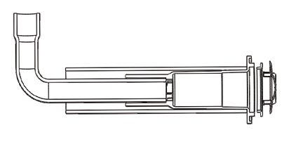
5. Install the new GloBrite light assembly: Push the light into the niche
while pulling the power cord from the junction box or transformer, making
sure the locking tabs in the back end of the light are properly aligned with the
niche openings (inside the niche).
Note: When using longer runs of cables or multiple lights per transformer, it is
recommended to use the 13 VAC or 14 VAC tap on the transformer.
Locking tabs Rubber seal
(back of light)
Light niche Light power cord Light assembly
(gunite niche
shown)
GloBrite Niche and Light
GloBrite White LED Light Installation and User’s Guide10
6. Place the light installation tool (P/N 620057) over the front of the light.
Turn the tool and light clockwise (less than an .3175 cm (1/8th. turn), while
pushing inward, until you feel the stop point. This indicates the light is
properly seated, locked and the niche is completely sealed.
Note: If the light does not turn smoothly, pull the light slightly out and make
sure that it’s seated properly and the niche is free of debris, then install the
light as described in step 6.
Rotate handle 1/8
turn clockwise to
install or counter-
clockwise 1/8 turn
to remove
Light installation
and remove tool
Align and insert tool pins with holes
in front of light
GloBrite® White Light Installation/Removal Tool
7. Before operating the GloBrite white light, fill the pool with water until the light
is completely submerged.
Note: The GloBrite white light should not be powered for more than 30
seconds if is not submersed in water.
8. Final check for proper GloBrite light operation: Switch on the main switch
or circuit breaker to the 12 VAC transformer and the switch that operates the
GloBrite light itself. The light should illuminate when the 12 VAC power is
applied. If not recheck the installation steps.
GloBrite White LED Light Installation and User’s Guide11
REPLACING THE GLOBRITE® LIGHT ASSEMBLY
(IN AN EXISTING POOL OR SPA)
Risk of Electrical Shock or Electrocution!
This underwater light must be installed by a licensed or certified
electrician or a qualified pool professional in accordance with
the current National Electrical Code (NEC), NFPA 70 or the
Canadian Electrical Code (CEC), CSA C22.1 and all applicable
local codes and ordinances. Improper installation will create an
electrical hazard which could result in death or serious injury to
pool users, installers or others due to electrical shock, and may
also cause damage to property.
Always disconnect the power to the pool light at the circuit
breaker before servicing the light. Failure to do so could result
in death or serious injury to service person, pool users or others
due to electrical shock.
IMPORTANT NOTICE:
THE GLOBRITE LIGHT IS A NON-SERVICEABLE LIGHT. THE
COMPLETE LIGHT ASSEMBLY MUST BE REPLACED.
Be sure that the pool or spa meets the requirements of the current National Electrical
Code (N.E.C.) Article 680-22 and all local codes and ordinances. A licensed or
certified electrician must install the electrical system to meet or exceed those
requirements before the underwater light is installed. Some of the requirements of the
National Electrical Code which the pool’s electrical system must meet are as follows:
• The Junction Box and the low voltage transformer is located at least
4 (four) inches (10.16 cm) above ground level or eight (8) inches
(20.3 cm) above maximum water level, whichever is higher. The Junction
Box must be at least 48 inches (1.22 m) from the edge of the pool. See
Figure 2 on page 7.
• The GloBrite light niche must be properly installed so that the top edge
of the lens of the GloBrite light is at least 4 inches below (not more than
48 inches below in Canada) the surface of the water in the pool or spa.
Figure 2 on page 7.
• To be certain that the pool or spa electrical system meets all applicable
requirements, the electrician should also consult the local building
department.
GloBrite White LED Light Installation and User’s Guide12
REPLACING THE GLOBRITE® LIGHT ASSEMBLY
(AFTER ELECTRICAL REQUIREMENTS ARE MET)
The following removal and installation instructions describe how to remove and install the
GloBrite light assembly.
Failure to bring the pool or spa’s electrical system up to code requirements
before installing the underwater light will create an electrical hazard which
could result in death or serious injury to pool users, installers, or others due to
electrical shock, and may also cause damage to property.
1. Switch off electrical switch or circuit breaker at the source. Note: DO
NOT service the light while in the pool water. Service the light
on the deck.
2. Remove Junction Box or Transformer cover. Disconnect the light wires and
attach a fish tape to the existing light power cord. This will assist in pulling
the replacement light power cord through the conduit back to the junction
box.
3. Remove the GloBrite light assembly from the pool or spa water and
place it on the deck: Using the provided installation tool (P/N 620057),
rotate the light assembly counter-clockwise about a 1/8th turn to release the
light from the niche as shown on page 10).
4. Slowly pull the light and attached power cord (with attached fish tape) out of
the niche. Pull the light’s power cord and fish tape out of the niche and place
the light on the deck.
5. Attach the new light power cord to the fish tape and carefully feed the fish
tape and cable to the junction box.
6. Install the light into the niche: Place the light installation tool over the front
of the light. Turn the tool and light clockwise while pushing inward, until you
feel the stop point. This indicates the light is properly seated, locked and the
electrical conduit, is completely sealed (see page 10).
Note: If the light does not turn smoothly, pull the light slightly out and be sure
that it’s seated properly and the niche is free of debris, then install the light
as described in step 5.
7. Connect the two (2) conductors to the corresponding circuit wires in the
Junction Box (black wire to power, white wire to common) and secure the
Junction Box cover in place.
8. Final check for proper GloBrite light operation: Switch on the main switch
or circuit breaker to the 12 VAC transformer and the switch that operates the
light itself. The light should illuminate when 12 VAC power is applied. If not
recheck the installation steps.
GloBrite White LED Light Installation and User’s Guide13
CONNECTING GLOBRITE® LIGHTS TO
EASYTOUCH® OR INTELLITOUCH® CONTROL SYSTEM
LOAD CENTER TO AN AUXILIARY RELAY
RISK OF ELECTRICAL SHOCK OR ELECTROCUTION
Always disconnect AC power to EasyTouch and IntelliTouch control system load
center at the circuit breaker before servicing, or removing the HIGH VOLTAGE FRONT
PANEL. Failure to do so could result in death or serious injury to installer, service
person, pool users, or others due to electrical shock.
1. EasyTouch or IntelliTouch Control System Load Center: Unlatch the
enclosure door spring latch, and open the door.
2. Discharge Electrostatic energy before removing the cover by first
touching the metal part of the enclosure.
3. Loosen the two (2) retaining screws from the HIGH VOLTAGE FRONT
PANEL. Remove the panel from the enclosure.
4. Run the GloBrite white light power cord to a auxiliary relay in the
EasyTouch/IntelliTouch load center.
5. Connect the 120 Volt side of a 12 VAC transformer to the LOAD SIDE of
one of the auxiliary (AUX) relays in the load center.
6. Connect the Neutral conductor from the 12 VAC transformer to the Neutral
bus bar in the load center.
7. After the connection has been completed, close the control panel and
secure it with the two (2) retaining screws.
8. Close the load center front door. Fasten the spring latch.
GloBrite White LED Light Installation and User’s Guide14
AUXILIARY RELAYS
AUX 1 EASYTOUCH 4 AUTOMATION CONTROL
®
AUX 1
LINE 1 LOAD 1
LINE 1
CIRCUIT BREAKER
GROUND
NEUTRAL
LOAD 1 120V/12V
Step Down Black
Neutral Transformer Black JUNCTION
(100W or 300W) White
Ground (see page 1 for White BOX
transformer Five WHITE GloBrite 12 VAC
load maximum) Lights require a 100 Watt
transformer.
EasyTouch® and IntelliTouch® Control System Load Center Wiring Diagram
GloBrite® White Light with Wall Switch Wiring Diagram
GloBrite White LED Light Installation and User’s Guide15
SETTING UP GLOBRITE® WHITE LIGHTS WITH
EASYTOUCH® AND INTELLITOUCH® CONTROL SYSTEM
EasyTouch® Control System
The following describes how to setup the GloBrite White Light from the EasyTouch® control
system indoor control panel or the EasyTouch control system wireless control panel. From
the EasyTouch control panel you can control the light shows.
To set up a GloBrite light circuit; assign the “Light Circuit Name” to the relay circuit
(example; AUX 3, as “Pool Light”) and “Function”: assign the name “Pool Light” circuit in
the Circuit Func. menu as a “light” circuit (IntelliBrite). After assigning the circuit name
and function, the light circuit name “Pool Light” can be setup in the CONFIG menu for light
position, color etc.
To assign a Circuit Name go to: MENU > SETTINGS > CIRCUIT NAMES
IntelliFlo Circuit Names
IntelliChlor Circuit #: 1/18
Circuit Names Circuit : AUX 1
Circuit Func. [POOL LIGHT ]
1. Press the Up/Down button to select a circuit number 1/18. Press the Up
button two times to select AUX 1 to choose this circuit for a light circuit On/
Off button. The circuit number (1/18) corresponds to its assigned circuit
name.
2. Press the Up/Down button to scroll through the list of preset names. Select
a name such as “Pool Light.” AUX 1 has now been assigned the circuit name
“Pool Light.”
To assign a Circuit Function go to: MENU > SETTINGS > CIRCUIT FUNC.
Circuit / Func. :
[POOL LIGHT ]
[INTELLIBRITE ]
Freeze: No
3. Press the Menu button to return to the Settings menu. Press the Down but-
ton to and select “Circuit Func.” Press the Right button to access the Circuit
Func. menu.
4. Press the Up/Down button to select the already assigned circuit name “Pool
Light.”
5. Press the Right button to view “Circuit Functions” to assign to light circuit
“Pool Light.”
6. Press the Up/Down button to select the type of light circuit function to use.
Select “INTELLIBRITE” for the GloBrite light circuit function.
7. Press the Menu button three times to return to the main screen.
Operating the GloBrite lights: The GloBrite white light is ready to operate using the
EasyTouch control panel button 1 (auxiliary 1 circuit). To access the Lights menu screen
(special Light Features), press Menu > Lights. The Lights menu settings are: MODES,
COLORS, ALL ON, ALL OFF, SYNC, MAGICSTREAM, CONFIG: From the Modes screen
you can control the color light shows. To access the Modes menu, press Menu > Lights >
Modes. See page 2 for GloBrite color light shows.
GloBrite White LED Light Installation and User’s Guide16
IntelliTouch® Control System
The following describes how to setup the GloBrite White Light from the IntelliTouch®
control system control panel. From the IntelliTouch® control system control panel you
can control the light shows. To access the GloBrite light screens, from the IntelliTouch
indoor control panel or the MobileTouch® Wireless Remote control panel.
Assigning a Circuit Name
To identify the GloBrite light connected to the auxiliary circuits (AUX 1, AUX 2) in
the IntelliTouch load center, you need to assign the GloBrite light circuit name to
the corresponding auxiliary circuits in the IntelliTouch indoor control panel. Choose
a circuit name from the preset list of names for the GloBrite light connected to the
auxiliary relay installed in the IntelliTouch load center.
Assigning a Circuit Name for the GloBrite Light: To assign a Circuit Name for the
GloBrite light, go to: MENU > SETUP > ADVANCED > CIRCUIT NAMES > ASSIGN
CIRCUIT NAMES > DISPLAY.
Selecting DISPLAY Screen 1, 2, 3, or 4: The auxiliary circuits that control the pool
and spa equipment can be accessed from the “Display” screen on the Indoor Control
Panel or MobileTouch wireless control panel. Selecting the button next to Display 1,
2, 3, or 4 displays the screen with circuits belonging to that particular expansion Load
Center or Power Center. “Feature Circuits” can also be assigned from this screen.
To assign circuit names for a specific display screen:
Display #1 - This screen shows circuit names for the filter pump, pool and spa
modes, and all high voltage auxiliary circuits connected to the main Load Center or
Power Center. Display #2 - This screen shows circuit names for the additional
auxiliary circuits connected to the first expansion center (Load Center or Power
Center).
Display #3 - This screen shows circuit names for the additional auxiliary circuits
connected to the second expansion center (Load Center or Power Center)
Display #4 - This screen shows circuit names for the additional auxiliary circuits
connected to the third expansion center (Load Center or Power Center).
To assign a GloBrite light circuit name for the MAIN SCREEN:
1. Select the button next to Display #1. These are the circuit names that will be
displayed on the Main Screen. Note: If there is an expansion Load Center or
Power Center installed, select the appropriate Display #2, #3, or #4 associ-
ated with that expansion Load Center or Power Center.
2. From the Main Display screen, press the button next to AUX 1.A small arrow
pointing to AUX 1 is displayed.
3. Use the Up and Down buttons at the bottom of the screen to scroll through
the alphabetical list of preset equipment names. Choose the equipment
name that matches the label name for button number 1 on the Load Center
Outdoor Control Panel.
4. Continue to name other auxiliary circuits (AUX2, AUX3, etc.): After selecting
the equipment name you want to use for AUX 1, press the button next to the
AUX 2 and choose a circuit name. The small arrow indicates which circuit is
selected for naming.
5. Repeat the process to assign the other equipment to circuits on this screen.
6. When you have finished assigning equipment circuit names, press the Save
button. Press the Exit button to return to the Main screen.
7. CONTINUE TO NEXT PAGE to set up the GloBrite “Function Circuit.”
GloBrite White LED Light Installation and User’s Guide17
Set up a GloBrite® Light Circuit Function
To setup an AUX circuit to control the GloBrite white light, assign the circuit light function
an auxiliary relay circuit (AUX 1), then assign the circuit name for that light circuit. The light
circuit name will appear on the main screen. Each GloBrite light must also be assigned a
circuit function.
To assign a Circuit Name for the GloBrite light, go to: MENU > SETUP > ADVANCED
> CIRCUIT FUNCTIONS
Setup a GloBrite light function circuit: Assign each light auxiliary relay circuit a
circuit name, then assign that light relay circuit in the “CIRCUIT FUNCTIONS” section,
as “INTELLIBRITE.”
To setup the GloBrite light circuit function (use the “IntelliBrite” circuit name):
1. Press the button next to the AUX button (the relay auxiliary circuit
connected to the GloBrite (IntelliBrite) light).
2. Press the right or left side (PREV/NEXT) button next to “INTELLIBRITE.”
Scroll through the circuit functions until “INTELLIBRITE” is displayed.
3. Press the SAVE button on the bottom of the screen. Press the EXIT button to
return to the main screen.
Assign the GloBrite light circuit to the Lights screen:
4. Press the Lights button on the bottom of the screen.
5. Press the right side button next to “CONFIGURE.”
6. Press the button next to “NONE” to assign an IntelliBrite light circuit to the
selected button. Light names can be setup to display on the left side for
“Spa” features and on the right side for the “Pool” features.
7. Press the top left or right side button to scroll through the available light cir-
cuits which can be used for the GloBrite (IntelliBrite) lighting features. Select
at the circuit name you wish to use. The displayed circuit names are circuit
names that were previously assigned when assigning a circuit function.
Operating and Selecting GloBrite (IntelliBrite® White Light) White Mode
Special Light Features: Up to twelve (12) IntelliBrite light circuits can be displayed on
the main Lights screen (special light features). From the Lights screen you can activate
the IntelliBrite lighting features (i.e., color swim, color set). Assuming each GloBrite
(IntelliBrite) light has its own relay and separate circuit.
Troubleshooting (GloBrite Lights)
Both of the LEDs are flashing: Check the light wiring connection to the junction
box at the pool side and to the AC power switch.
The light will not illuminate:
Check the light wiring connection to the junction box at the pool side and to the AC
power switch. Be sure that there is proper AC power applied to the light.
GloBrite White LED Light Installation and User’s Guide18
GloBrite® White Lights Parts List and Replacement Kits
GloBrite Lights
Part No. Description
602053 GloBrite 12 VAC 30’ cord
602054 GloBrite 12 VAC 50’ cord
602055 GloBrite 12 VAC 100’ cord
602056 GloBrite 12 VAC 150’ cord
GloBrite Bundles
Part No. Description
619993 Gunite Combo #1- 1 GloBrite 100’ w/300W transformer & Gunite niche
619994 Gunite Combo #2 - 2 GloBrite 100’ w/300W transformer & 2 Gunite
niches
620051 Fiberglass combo #1- 1 GloBrite 100’ w/300W txfmr & Fiberglass niche
620052 Fiberglass combo #2 - 2 GloBrite 100’ w/300W txfmr & 2 Fiberglass
niches
620080 Vinyl combo #1- 1 GloBrite 100’ w/300W txfmr and vinyl niche
620081 Vinyl combo #2 - 2 GloBrite 100’ w/300W txfmr and two vinyl niches
GloBrite Light Niches
Part No. Description
620039 Vinyl Niche for GloBrite
620040 Gunite Niche for GloBrite
620041 Fiberglass Niche for GloBrite
620093 Fiberglass Niche for GloBrite (Blue)
620094 Fiberglass Niche for GloBrite (Gray)
GloBrite Light Replacement Kits
Part No. Description
620055 Fiberglass (Washer and Gasket)
620056 Color Ring (Color Ring and Plaster Cover)
620057 O-Ring (O-Ring, Insertion Tool)
620058 Nut (Fiberglass/Vinyl Nut)
620314 Glare Shield
602136 Vinyl Blue, Gaskets (3), Front Face Plate (Blue), Screws (12)
602137 Vinyl Gray, Gaskets (3), Front Face Plate (Gray), Screws (12)
602138 Vinyl White, Gaskets (3), Front Face Plate (White), Screws (12)
GloBrite White LED Light Installation and User’s Guide19
Note
GloBrite White LED Light Installation and User’s Guide20 1620 HAWKINS AVE., SANFORD, NC 27330 • (919) 566-8000 10951 WEST LOS ANGELES AVE., MOORPARK, CA 93021 • (805) 553-5000 WWW.PENTAIR.COM All Pentair trademarks and logos are owned by Pentair, Inc. GloBrite®, IntelliFlo®, IntelliBrite®, EasyTouch®, IntelliTouch®, SunTouch®, IntelliChlor®, MobileTouch® and SAm® are trademarks and/or registered trademarks of Pentair Water Pool and Spa, Inc. and/or its affiliated companies in the United States and/ or other countries. Unless expressly noted, names and brands of third parties that may be used in this document are not used to indicate an affiliation or endorsement between the owners of these names and brands and Pentair Water Pool and Spa, Inc. Those names and brands may be the trademarks or registered trademarks of those third parties. Because we are continuously improving our products and services, Pentair reserves the right to change specifications without prior notice. Pentair is an equal opportunity employer. © 2020 Pentair Water Pool and Spa, Inc. All rights reserved. This document is subject to change without notice. *620218* P/N 620218 REV E 1/2020 GloBrite White LED Light Installation and User’s Guide
LÁMPARA BLANCA LED GLOBRITE®
PARA PISCINAS Y SPA

                           GUÍA DE INSTALACIÓN
                                  Y DE USUARIO

  INSTRUCCIONES DE SEGURIDAD IMPORTANTES
     LEA Y SIGA TODAS LAS INSTRUCCIONES
        GUARDE ESTAS INSTRUCCIONES
         Guía de instalación y de usuario para lámpara LED blanca GLOBRITE de piscina/spa
Soporte técnico
Teléfono: (800) 831-7133 - Fax: (800) 284-4151
www.pentair.com
Contenido
ADVERTENCIA IMPORTANTE E INSTRUCCIONES DE SEGURIDAD............................ i-ii
Información general de la lámpara LED blanca GloBrite para piscinas ........................... 1
Controlar las lámparas blancas GloBrite con un interruptor de pared............................... 1
Utilizar un transformador externo para varias lámparas GloBrite de 12 VAC ................... 1
Máxima potencia de consumo utilizando varias luces LED
(con un transformador de 300 W) .................................................................................... 1
Controlar las lámparas blancas GloBrite con un interruptor de pared............................... 2
Instalación de lámpara GloBrite (construcción de piscina nueva)..................................... 3
Instalar la manga y el nicho para lámparas GloBrite
(una vez que se cumplen los requisitos eléctricos)................................................................. 3
Instalar la manga y el nicho para lámparas GloBrite en una piscina de cemento/gunita ....... 5
Opción 1: Manga y nicho para lámparas con cono .......................................................... 5
Opción 2: Conducto hacia el nicho para lámparas ........................................................... 6
Instalar la lámpara GloBrite en una piscina de fibra de vidrio ................................................ 7
Instalar la lámpara GloBrite en una piscina de vinilo .............................................................. 8
Instalar el ensamblaje de lámparas GloBrite (después de la instalación del nicho)................ 9
Reemplazar el ensamblaje de lámparas GloBrite (en una piscina o spa existente) .............. 11
Reemplazar el ensamblaje de lámparas GloBrite (una vez que se
cumplan los requisitos eléctricos).......................................................................................... 12
Conectar las lámparas GloBrite al centro de carga EasyTouch/IntelliTouch ......................... 13
Lista de partes y kits de reemplazo para lámparas GloBrite® .............................................. 19
LEA Y SIGA TODAS LAS INSTRUCCIONES DE ESTE MANUAL.
P/N 620218 Rev E 1/2020i
INSTRUCCIONES IMPORTANTES DE ADVERTENCIA Y SEGURIDAD
NO INSTALAR Y UTILIZAR ESTA LÁMPARA CORRECTAMENTE PUEDE
PELIGRO CAUSAR LESIONES FÍSICAS O LA MUERTE.
PELIGRO LOS INSTALADORES, OPERADORES Y PROPIETARIOS DE LA PISCINA
DEBEN LEER ESTAS ADVERTENCIAS Y TODAS LAS INSTRUCCIONES
ANTES DE USAR LA LÁMPARA DE PISCINA Y/O SPA.
ADVERTENCIA L a m ay o r í a d e l o s c ó d i g o s r e g i o n a l e s y e s t a t a l e s r e g u l a n l a
construcción, instalación y operación de spas y piscinas públicas, así
como la construcción de spas y piscinas residenciales. Es importante cumplir con esos
códigos, muchos de los cuales regulan directamente la instalación y el uso de este producto.
Consulte sus códigos de construcción y salud regionales para obtener más información.
AVISO IMPORTANTE. Atención del instalador: Esta Guía de instalación y de usuario
(“Guía”) contiene información importante sobre la instalación, el funcionamiento y el
uso seguros de esta lámpara sumergible para piscinas y spa. Se le debe proporcionar
esta Guía al dueño u operador del equipo.
ADVERTENCIA
Antes de instalar este producto, lea y siga todas las instrucciones y preste
atención a las advertencias que se incluyen en esta Guía. No seguir las
instrucciones ni prestar la debida atención a las advertencias puede ocasionar daños a la
propiedad, lesiones graves y hasta la muerte. Llame al (800) 831-7133 para obtener copias
adicionales y gratuitas de las instrucciones. Visite www.pentairpool.com para obtener más
información sobre estos productos.
RIESGO DE DESCARGAS ELÉCTRICAS O DE ELECTROCUCIÓN:
PELIGRO ANTES DE TRABAJAR CON la lámpara, siempre desconecte la
alimentación de las lámparas de la piscina o el spa en el disyuntor
fuente antes de hacer el mantenimiento de la lámpara. Si incumple
con esto, puede dar como resultado la muerte o lesiones serias a la
persona que realiza el mantenimiento, a los usuarios de la piscina o
a terceros debido a un choque eléctrico. Cuando instale y use estos
equipos eléctricos, siempre se deben seguir las precauciones de
seguridad básicas.
Esta lámpara sumergible debe instalarla un electricista certificado o con licencia, o en todo
caso, un equipo profesional calificado de mantenimiento de conformidad con el Código Nacional
Eléctrico (NEC) vigente, NFPA 70 o con el Código Eléctrico Canadiense (CEC), CSA C22.1.
Además, deben respetarse todos los códigos y las ordenanzas regionales aplicables. Una
instalación incorrecta representa un peligro eléctrico que podría dar como resultado la muerte o
una seria lesión a los usuarios de la piscina, instaladores u otros debido a un choque eléctrico,
y también podría causar daños a la fuente de alimentación. Siempre desconecte la alimentación
de la lámpara de la piscina desde el disyuntor antes de realizar el mantenimiento de la lámpara.
Si incumple con esto, podría dar como resultado la muerte o lesiones serias a la persona que
realiza el mantenimiento, a los usuarios de la piscina o a otros debido a un choque eléctrico.
ADVERTENCIA Para los países que cumplen con las normas reguladoras de la Comisión
Electrotécnica Internacional (IEC): Las lámparas deben ser instaladas por un
electricista certificado o con licencia, o en todo caso, una persona calificada de mantenimiento de
piscinas, en conformidad con el IEC 364-7-702 actual y todos los códigos y las ordenanzas locales
vigentes. Una instalación incorrecta representa un peligro eléctrico que podría dar como resultado
la muerte o una seria lesión a los usuarios de la piscina, instaladores u otros debido a un choque
eléctrico, y también podría causar daños a la propiedad.
Guía de instalación y de usuario para lámpara LED blanca GLOBRITE de piscina/spaii
INSTRUCCIONES IMPORTANTES DE ADVERTENCIA Y SEGURIDAD
INSTALADORES E INSPECTORES
LA LÁMPARA LED BLANCA GLOBRITE® Y EL NICHO DE PLÁSTICO COMPONEN UN
SISTEMA DE ILUMINACIÓN COMPLETO DE BAJO VOLTAJE Y SIN METALES. ESTA
CONFIGURACIÓN NO EXIGE CONEXIÓN O PUESTA A TIERRA CUANDO RECIBE
ALIMENTACIÓN DE UN TRANSFORMADOR DE 100W O 300W INCLUIDO EN LA LISTA
(LISTA EN LA PÁGINA 19) Y SE INSTALA EN CUMPLIMIENTO DEL CÓDIGO NACIONAL
ELÉCTRICO VIGENTE (NEC).
DISPOSICIONES DE LA NEC SOBRE ILUMINACIÓN: Cuando la UL incluyó en su lista que
las lámparas LED de bajo voltaje se utilizan con los nichos aprobados para lámparas
GloBrite (como se menciona en la página 19), el NEC actual añade una excepción sobre
la conexión y el cableado a tierra de las luminarias en el Artículo 680.6 y 680.23
DISPOSICIONES DE NEC SOBRE CONEXIONES EN AGUA DE PISCINA: Para las conexiones
en agua de piscina exigidas por el Artículo 680.26C de NEC, se considera que las piscinas
de cemento son conductoras (consulte 680.26 [b] [1]) debido a la porosidad del cemento y
la unión con las varillas. No se requiere conexión adicional.
LUMINARIAS FIJAS PARA PISCINAS Y SPA: Siga estas pautas al instalar o reemplazar
luminarias fijas para piscinas y spas de Pentair Aquatic Systems:
- PARA CONTROLAR LAS LÁMPARAS, UTILICE ÚNICAMENTE UN TRANSFORMADOR DE
AISLAMIENTO DE SEGURIDAD.
Nota: Conecte los tres conductores a los cables de circuito correspondientes en la caja
de conexiones (cable negro a alimentación, cable blanco a común y cable verde a tierra).
ESPECIFICACIÓN SOBRE LUMINARIAS FIJAS PARA PISCINAS Y SPA: 12 VCA 50/60 Hz
NOTA IMPORTANTE: LA LÁMPARA BLANCA GLOBRITE NO PUEDE
RECIBIR MANTENIMIENTO. SE DEBE REEMPLAZAR LA LÁMPARA EN SU
TOTALIDAD.1
Vistazo general de la lámpara LED multicolor GloBrite® para piscinas
Este manual describe cómo instalar y reemplazar la lámpara LED blanca GloBrite® para piscinas
y spas. La lámpara LED blanca GloBrite le permite elegir entre tres niveles de brillo. Para más
información, consulte la página 2.
El accesorio de opcional GloBrite ™ antirreflejos de la pantalla (P/N 620314 -
vendido por separado] es para su uso en GloBrite ™ luces LED para reducir
reflejo de la luz.
Controlar las lámparas LED GloBrite con un interruptor de pared
La lámpara LED GloBrite se puede controlar manualmente utilizando un interruptor de luces estándar
que se monta en la pared. Se pueden conectar varias lámparas GloBrite mediante una caja de con-
exiones y un transformador de aislamiento de 12 VCA a un único interruptor, de modo que se puedan
encender y apagar todas las luces simultáneamente. Para ver el diagrama del cableado, consulte la
página 13.
Utilizar un transformador de aislamiento de seguridad externo para varias lámparas
GloBrite de 12 VCA.
Cuando utiliza varias lámparas GloBrite de 12 VCA en un transformador de aislamiento de seguridad,
se recomienda utilizar no más de cinco (5) lámparas GloBrite. Para cables largos con una sola
lámpara, se recomienda no superar los 45,72 m (150 pies) de cable total entre el transformador de
aislamiento de 12 VCA y la lámpara GloBrite.
Nota: Si es necesario un cable
más largo, se recomienda
utilizar transformadores de
Transformador Calibre 12 Caja de C
aislamiento de seguridad de
100W independientes para
de 100 watts (mínimo) cada lámpara con cables de
no más de 45,72 m (150 pies)
entre los transformadores y
las lámparas.
45,72 m
(150 pies)
Máxima potencia de consumo con varias lámparas LED blancas
GloBrite (con un transformador de aislamiento de 300 watts)
¡IMPORTANTE! Cuando se utilizan varias lámparas LED blancas Pentair de 12 VCA en una piscina
o en un spa, la potencia de consumo total permitida para las lámparas es 300W. La potencia de
consumo individual por lámpara es la siguiente:
• Una lámpara LED de color/blance GloBrite para piscina tiene un máximo de 15 watts
• Una lámpara LED AmerBrite blanca (500W) para piscina tiene un máximo de 51 watts
• Una lámpara LED AmerBrite blanca (400W) para piscina tiene un máximo de 44 watts
• Una lámpara LED AmerBrite blanca (300W) para piscina tiene un máximo de 36 watts
• Una lámpara LED AmerBrite de color para piscina tiene un máximo de 36 watts
• Una lámpara LED IntelliBrite de color para piscina tiene un máximo de 30 watts
• Una lámpara LED IntelliBrite de color para spa tiene un máximo de 18 watts
Guía de instalación y de usuario para lámpara LED blanca GLOBRITE de piscina/spa2
Controlar las lámparas blancas GloBrite® con un interruptor de pared
Las lámparas blancas GloBrite® se pueden controlar con un interruptor convencional que se monta
en la pared. Se pueden conectar varias lámparas blancas mediante una caja de conexiones y un
transformador de 12 VCA a un único interruptor, de modo que se puedan encender y apagar las
lámparas al mismo tiempo. Las lámparas blancas GloBrite® se controlan enviando corriente AC al
transformador de 12 VCA desde un interruptor de pared convencional. Al alternar el interruptor entre
ON y OFF un número específico de veces, puede elegir entre tres niveles de brillo.
Encender las lámparas LED blancas GloBrite
Nota: La lámpara LED blanca GloBrite se envía de fábrica en el modo de 100 % brillo.
Cuando se enciende la lámpara blanca GloBrite, su nivel de brillo es el mismo que el último que se
aplicó. Nota: Si la alimentación de la lámpara se corta por más de cinco (5) segundos, se aplicará el
último nivel de brillo que se guardó.
Seleccionar un nivel de brillo para la lámpara blanca GloBrite con
un interruptor de pared
Las lámparas blancas GloBrite le permiten elegir entre tres niveles de brillo (100%, 75% y 50%).
Cuando se enciende la lámpara blanca GloBrite, comienza en el nivel máximo de brillo (100 %).
Si se ha configurado al nivel medio (75 %) o bajo (50 %) esto encenderá en el 100 % entonces
se adaptan al nivel de resplandor correcto.
Para seleccionar uno de los tres niveles de brillo (100 %, 75 % y 50 %) de GloBrite, primero
encienda las lámparas, luego alterne rápidamente el interruptor entre ON (ENCENDIDO) y OFF
(APAGADO) el número de veces específico para seleccionar el nivel de brillo deseado.
La selección del brillo de las lámparas se realiza de la siguiente manera:
• 100 % de brillo: Mueva el interruptor a OFF y luego rápidamente a ON para encender
las lámparas con 100 % de brillo.
• 75 % de brillo: Alterne el interruptor OFF-ON-OFF-ON y las lámparas se encenderán
al 100 % y se atenuarán a 75 % después de 1 segundo.
• 50 % de brillo: Mueva el interruptor OFF-ON-OFF-ON-OFF-ON y las lámparas se
encenderán al 100 %, un segundo después se atenuarán a 75 % y otro segundo
después se atenuarán a 50 %.3
INSTALACIÓN DE LÁMPARA GLOBRITE®
(NUEVA CONSTRUCCIÓN DE PISCINA)
A continuación se describe cómo instalar la lámpara GloBrite®.
ANTES DE COMENZAR: La siguiente información describe las tareas que el
electricista debe realizar antes de instalar la unidad de iluminación. Vea la Figura 1
de la página 6.
ADVERTENCIA
Verifique que la piscina o el spa cumplan con los requisitos del Artículo 680-22 del Código
Nacional Eléctrico (NEC) actual y todos los códigos y ordenanzas locales vigentes. Un
electricista con licencia o certificado debe instalar el sistema eléctrico para cumplir o superar
estos requisitos antes de instalar la lámpara sumergible. Algunos requisitos del Código Nacional
Eléctrico, que el sistema eléctrico de la piscina debe cumplir, son los siguientes:
• La caja de conexiones y el transformador de bajo voltaje se ubica al menos a
10,16 cm (4 pulgadas) sobre el nivel del suelo u 20,3 cm
(8 pulgadas) sobre el máximo nivel del agua, el que sea mayor. La caja de
conexiones se debe encontrar al menos a 1,22 m (48 pulgadas) del borde de la
piscina. Vea la Figura 1 de la página 7.
• El nicho para lámparas GloBrite se debe instalar correctamente de modo que el
borde superior de la lente de la lámpara de color GloBrite esté al menos 10.16 cm
(4") debajo (no más de 1,22 m (48") debajo en Canadá) de la superficie del agua
de la piscina o el spa.
• Para asegurarse de que el sistema eléctrico de la piscina o del spa cumpla con
todos los requisitos vigentes, el electricista debe consultar con el departamento
local de construcciones.
INSTALAR LA MANGA Y EL NICHO DE LA LÁMPARA GLOBRITE
(UNA VEZ QUE SE CUMPLEN LOS REQUISITOS ELÉCTRICOS)
Existen tres tipos de nichos de lámparas LED GloBrite para piscinas o spa:
Cemento/gunita, fibra de vidrio o recubrimiento vinilo.
Nota: El nicho para lámparas GloBrite se debe instalar en la pared de la piscina (u otra
instalación con agua) o sobre ella con la parte superior del lente a no menos de 10,2 cm
(4") debajo del nivel de agua normal de la piscina. La lámpara blanca GloBrite también se
puede instalar en el fondo de la piscina (boca arriba).
Guía de instalación y de usuario para lámpara LED blanca GLOBRITE de piscina/spaYou can also read