TIPPMANN - PAINT-SUPPLY.net
←
→
Page content transcription
If your browser does not render page correctly, please read the page content below
TIPPMANN
                                                        ®

            2955 Adams Center Road, Fort Wayne, IN 46803 USA
                    P) 260-749-6022 • F) 260-749-6619
                           www.Tippmann.com

                                  ®

   TACTICAL COMPACT RIFLE
.68 CALIBER PAINTBALL MARKER
       OWNER’S MANUAL
   CALIBRE .68 LANCEUR DE PAINTBALL
         MANUEL D’UTILISATION

  MACADOR PARA PAINTBALL CALIBRE .68
        MANUAL DEL USUARIO

                                                               TP04225
                                                                  02/15
E
N
G WARNING
L This is not a toy. Misuse may cause serious injury or death.
I
Eye, face, and ear protection designed for paintball must be
S
worn by the user and any person within range. We recommend
H
you be at least 18 years old to purchase. Persons under 18
must have adult supervision when using this product. Read
the Owner’s Manual before using this product.
F AVERTISSEMENT
R Ceci n’est pas un jouet. Une mauvaise utilisation peut causer
A de sérieuses blessures ou la mort. Une protection pour les
N yeux, la tête et les oreilles adaptée au paintball doit être portée
Ç par l’utilisateur ainsi que tous les utilisateurs situés dans
A le champ de tir. Nous recommandons que l’acheteur ait au
I moins 18 ans. Les personnes de moins de 18 ans doivent être
S supervisées par un adulte durant l’utilisation de ce produit.
Lisez le Manuel avant d’utiliser ce produit.
ADVERTENCIA
Esto no es un juguete. Un uso inapropiado puede causar
E serias heridas o la muerte. Ojos, cara y oidos deben ser
S protegidos todo el tiempo, con la protección diseñada para
P paintball tanto por jugadores como por cualquier persona
A que este en el radio de alcance. Recomendamos al menos 18
Ñ años para la compra y uso. Las personas menores de 18 años
O deben usar este producto bajo la supervisión de un adulto. Lea
L el Manual del Usuario antes de usar este producto.
2 TP04225 Ver. 02/15E
N
WARNING G
L
Safety is Your Responsibility I
Read and familiarize yourself and any other user of this S
marker with the safety instructions in this manual. Follow these H
instructions when using, working on, transporting, Push in for Safety
or storing this marker.
Always keep the trigger safety in Safe mode when
not in a shooting situation, see instructions on
page 6.
Always keep the barrel blocking device installed
when not in a shooting situation, see instructions Barrel
Blocking Device
on page 4.
AVERTISSEMENT
La Securite est Votre Responsabilite
Lisez et familiarisez-vous ainsi que tout autre utilisateur de ce F
lanceur avec les instructions de securite contenues dans ce R
manuel. Suivez ces instructions lorsque vous utilisez, travaillez A
sur, transportez, ou entreposez ce lanceur. Securite Verrouillee
N
Toujours maintenir le bouton en mode sécurité Ç
lorsque vous n’êtes pas en situation de jeu, voir les A
instructions de la page 3. Gardez toujours le I
dispositif de blocage du canon S
installe lorsque vous n’etes pas en situation de Dispositif de
tir comme indique dans les instructions en page 1. Blocage du Canon
ADVERTENCIA
La Seguridad es Su Responsabilidad
Lea y familiaricese usted y cualquier otro usuario de este
marcador con las instrucciones de seguridad de este manual. Siga
estas instrucciones cuando se utiliza, trabajando, transporte, o
almacenar este marcador. Presione el Seguro
E
Mantenga siempre el seguro del gatillo seguridad en S
modo seguro cuando no se encuentra en una P
situación de captura, consulte las instrucciones en A
la página 3. Ñ
Mantenga el mecanismo de bloqueo del barril O
instalado cuando no este haciendo disparos Mechanismo de
Bloqueo del Barril L
como se ilustra en la página 1.
TP04225 Ver. 02/15 3E
N Tippmann Sports, LLC
2955 Adams Center Road, Fort Wayne, IN 46803 USA
G P) 260-749-6022 • F) 260-749-6619 • www.Tippmann.com
L Tippmann Sports Europe, SPRL
I Rue du Mont D’Orcq 16, Z.I. Tournai Ouest, 7503 Froyennes, Belgium
S Telephone +32 (0) 69 549 578 • europeservice@tippmann.com • www.Tippmann.com
H
WARNING
This is not a toy. Misuse may cause serious injury or death. Eye,
face, and ear protection designed for paintball must be worn by
the user and any person within range. We recommend you be at
least 18 years old to purchase. Persons under 18 must have adult
supervision when using this product. Read the Owner’s Manual
before using this product.
WARNING
Always keep the barrel blocking device installed except when your
marker is in use. Always make sure that the trigger safety is in the
safe mode (see instructions on page 6) and the barrel blocking device
is properly installed on your marker according to the instructions to
prevent damage to property, serious injury, or death.
Barrel Blocking Device Installation Instructions
1. Place the barrel blocking device onto the barrel and loop the cord under the grip, and
position at the back of the grip as shown.
2. Push in the button of the cord retainer and pull the cord through it until the retainer is
snug against the back of the grip. Release the cord retainer button. Keeping the cord
as tight as possible, leave
just enough cord elasticity to
pull the cord retainer from the
marker to remove the Barrel
Blocking Device for firing.
3. After the cord length
is properly adjusted,
lock the cord length Barrel
by tying a knot in the Blocking
cord against the back of the Device
retainer as shown. Cord
Retainer
4. Before and after playing,
inspect the barrel blocking
device. Replace the barrel
blocking device if the cord is damaged or there is a loss of cord elasticity.
5. Clean the barrel blocking device with plain, warm water and store out of sunlight in a dry
area when not in use.
4 TP04225 Ver. 02/15E
N
G
by TIPPMANN
®
L
I
S
CONGRATULATIONS on your purchase of a Tippmann Tactical Compact Rifle (TCR) paintball H
marker. We believe our TCR marker to be the most versatile magfed marker in paintball. Your
Tippmann TCR marker will provide many years of dependable service if cared for properly.
Please take time to read this manual thoroughly and become familiar with your Tippmann
TCR marker’s parts, operation, and safety precautions before you attempt to load or fire this
marker. If you have a missing or broken part, or need assistance, please contact Tippmann
Customer Service at 1-800-533-4831 for fast, friendly service.
TABLE OF CONTENTS
Barrel Blocking Device Installation Instructions.......................................................................4
Warning/Liability Statement.....................................................................................................6
Getting Started........................................................................................................................8
1. CO2 Cartridge Installation...........................................................................................8
2. Removing the Magazine and Loading.........................................................................9
3. Firing the Marker.........................................................................................................9
4. Unloading the Magazine............................................................................................10
5. Flip Up Sights............................................................................................................10
6. Vertical Folding Grip..................................................................................................10
7. Hopper Feed Option..................................................................................................10
Velocity Adjustment...............................................................................................................11
CO2 Cartridge Removal........................................................................................................11
Removing an Unused CO2 Cartridge (Non-Punctured)................................................11
Removing a Used CO2 Cartridge (Punctured)..............................................................12
Adjust TCR for CO2 Cartridges.....................................................................................12
Cleaning & Maintenance.......................................................................................................12
Magazine Disassembly, Reassembly, and Testing................................................................13
TCR Disassembly/Assembly.................................................................................................14
Firing Valve Disassembly/Assembly . ...........................................................................16
Air Valve Disassembly/Assembly...................................................................................16
Puncture Valve Disassembly/Assembly.........................................................................17
Regulator Disassembly/Assembly.................................................................................18
Remote Line Adapter Assembly............................................................................................18
Hopper Feed Installation.......................................................................................................18
Release Pressure From a Marker That Will Not Fire.............................................................19
Regulator Pressure Relief Valve Adjustment.........................................................................19
Troubleshooting.....................................................................................................................20
Using a Remote Line with TCR.............................................................................................22
Air/CO2 Cylinder Warnings...................................................................................................23
Air/CO2 Cylinder Safety Tips.........................................................................................24
Repairing Air/CO2 Cylinder Leaks.................................................................................24
Storage . ...............................................................................................................................25
Specifications........................................................................................................................25
TCR Parts Diagram and Parts List.................................................................................. 26-28
Warranty and Repair Information..........................................................................................30
TP04225 Ver. 02/15 5E
N Warning/Liability Statement
G
This marker is classified as a dangerous weapon and is surrendered by Tippmann Sports,
L
LLC with the understanding that the purchaser assumes all liability resulting from unsafe
I handling or any action that constitutes a violation of any applicable laws or regulations.
S Tippmann Sports, LLC shall not be liable for personal injury, loss of property or life resulting
H from the use of this weapon under any circumstances, including intentional, reckless,
negligent or accidental discharges.
All information contained in this manual is subject to change without notice. Tippmann Sports,
LLC reserves the right to make changes and improvements to products without incurring any
obligation to incorporate such improvements into products previously sold.
If you as a user do not accept liability, Tippmann Sports, LLC requests you do not use a
Tippmann Sports, LLC marker. By using this paintball marker you release Tippmann Sports,
LLC of any and all liability associated with its use.
SAFETY IS YOUR RESPONSIBILITY!
WARNING
Except when your TCR marker is in use,
always make sure that the trigger safety is
in Safe mode, and that the barrel blocking
device is properly installed (see page 4).
To turn ON the trigger safety (Safe mode),
push in the safety button (arrow) as
shown at right.
To turn OFF the trigger safety (Fire
mode), push in the safety button from the
opposite side of the receiver.
The ownership of this marker places upon you the total responsibility of its safe and lawful
use. You must observe the same safety precautions as you would any firearm to assure
the safety of not only yourself but everyone around you. Outlined here are some general
precautions to be aware of. The user should at all times use caution and common sense when
using this marker and always remember that the game of paintball can only survive and grow
if it remains SAFE!
• Do not load or fire this marker until you have completely read this manual and are
familiar with its safety features, mechanical operation and handling characteristics.
• Handle this and any marker as if it were loaded at all times.
• Keep your finger off the trigger until you are ready to shoot.
• Do not look down the barrel of a paintball marker. Accidental discharge into the eyes
may cause permanent injury or death.
• Keep the marker in Safe mode until ready to shoot (see Warning above).
• Keep the barrel blocking device installed on marker when not shooting (page 4).
• Never point the marker at anything you do not intend to shoot.
6 TP04225 Ver. 02/15E
• Never fire your marker at anything you do not intend to shoot because there may be N
paintballs or foreign debris lodged in the chamber, barrel, and/or the marker valve. G
• Do not shoot at fragile objects such as windows. L
I
• Never fire your marker at personal property of others. The paintball impact can S
cause damage and the paint can stain the finish of automobiles, houses, etc.
H
• Always keep the muzzle pointed down or in a safe direction, even if you stumble or fall.
• Eye, face, and ear protection designed specifically to stop paintballs in the form of
goggles and full face mask meeting ASTM Specification F 1776 must be worn by the
user and any person within range.
• Never shoot at a person who is not protected by eye, face, and ear protection
designed for paintball.
• Pressurize and load the marker only when the marker will be immediately used.
• Store the marker unloaded and degassed in a secure place.
NOTE: Before storing or disassembling, be sure to remove paintballs and air/CO2
supply (see unloading and air/CO2 removal instructions on pages 10 -12). Make sure
the trigger safety is in Safe mode (page 6) and install the barrel blocking device (page 4).
• Do not field strip or otherwise disassemble this marker while it is pressurized with
air/CO2 supply.
• Dress appropriately when playing the game of paintball. Avoid exposing any skin
when playing the game of paintball. Even a light layer will absorb some of the
impact and protect you from the paintballs.
• Keep exposed skin away from escaping gas when installing or removing air/CO2
cylinder or if the marker or air/CO2 supply is leaking. Compressed air, CO2, and
nitrogen gasses are very cold and can cause frostbite under certain conditions.
• Use only .68 caliber paintballs. Never load or fire any foreign objects.
• Avoid alcoholic beverages before and during the use of this marker. Handling
markers while under the influence of drugs or alcohol is a criminal disregard for
public safety.
• Avoid shooting an opponent at point blank, 6 feet or less.
• Familiarize yourself with instructions listed on air/CO2 cylinder or adapter. Contact
the air/CO2 cylinder or adapter manufacturer with any questions.
• Read the Air/CO2 Cylinder Warnings and Safety Tips on pages 23–24 before
beginning the cylinder installation or removal.
• Always measure your marker’s velocity before playing paintball and never shoot at
velocities in excess of 300 feet per second (see instructions on page 11).
• Do not brandish or display this product in public as it may cause confusion and may
be a crime. Police or others may mistake this product for a real firearm. Altering the
coloration or markings required by state or federal law to make the product look
more like a firearm is dangerous and may be a crime.
TP04225 Ver. 02/15 7E
N Getting Started
G • Eye protection designed for paintball use must be worn by the user and any person
L within range.
I • Do not disassemble this marker while it is pressurized.
S • Do not pressurize a partially assembled marker.
• Read each step completely before performing the instruction.
H
NOTE: Carefully hand start all threaded parts when assembling, and do not overtighten, as
this may potentially strip the threaded parts. In this manual, item numbers of parts are in
parentheses. You can also find these item numbers in the Parts Diagram on pages 26-27.
WARNING
Keep exposed skin away from gas
escape points (arrows) when installing
or removing a CO2 cartridge, or if
the marker or air supply is leaking.
Compressed air, CO2, and nitrogen
gasses are very cold, and can cause
frostbite under certain conditions. Eye protection designed for
paintball use must be worn by the user and any person within range.
1. CO2 Cartridge Installation
If you intend to use a Remote Line with the TCR, read the Air/CO2 Cylinder Warnings,
Safety Tips, and Removal on pages 23-24 before beginning the cylinder installation. Do not
pressurize a partially assembled marker. Follow the Remote Line instructions starting on page
22, then go to step 2 on page 9.
a. Put the trigger safety in Safe mode (see page 6)
and install the barrel blocking device (see page 4).
b. Open the left side Picatinny Rail as shown.
c. If applicable, tip the muzzle end of the Barrel
downward to allow an existing CO2 cartridge to
clear the opening.
d. If applicable, tilt the marker to the left and raise the
muzzle upwards. An existing CO2 cartridge will fall
from the marker.
e. Clean the small end of a full 12 gram CO2
cartridge. Tip the muzzle downward and insert a
new cartridge into the marker oriented as shown
by the arrow at right.
f. Close the left side Picatinny Rail to the marker.
Note: The CO2 cartridge is NOT punctured during
installation. After you move the trigger safety to Fire mode,
the first pull of the Trigger punctures the CO2 cartridge
without firing. You can hear the CO2 cartridge pressurize
the marker. Your marker is now ready to fire on the next
Trigger pull.
IMPORTANT: If your marker begins to leak gas, keep exposed skin away from the escaping
gas (the arrows in the WARNING illustration above show gas escape points) and follow CO2
Cartridge Removal instructions on page 11 (on page 22 for markers using a Remote Line)
8 TP04225 Ver. 02/15E
and then go to Troubleshooting on page 20. N
If you want to move the CO2 access door to the other side of the marker, follow step 5 on G
page 15 in TCR Disassembly/Assembly. L
2. Removing the Magazine and Loading I
The barrel blocking device must be installed (see page 4) and the trigger safety in Safe mode S
(see arrow at right and also see page 6). H
A seven ball Magazine and a twelve ball Magazine are provided. Safety Button
The 12 ball magazine is capable of holding First Strike rounds
as well as .68 caliber paintballs. If you choose to use First Strike
paintballs, read and understand the Warning below. The 7 ball Magazine Release
magazine will only hold .68 caliber paintballs.
a. To remove the Magazine, push in the Magazine
Release button and the Magazine ejects out the
bottom of the grip. Ball Carrier
b. For the 7 ball magazine, use tabs on the side of the
Ball Carrier to pull it down until it locks into place at
the bottom of the Magazine. Load 12 paintballs into
the 12 ball magazine to lock down the ball carrier.
c. Keep the Magazine vertical as shown, and insert one
paintball at a time into the top of the Magazine until full.
Paintballs in the Magazine are not under pressure until
the Magazine is inserted into the marker.
d. To insert a loaded Magazine into the marker, slide the Magazine into
the grip until you hear it lock into place.
WARNING
This paintball marker is not a toy. Misuse may cause serious injury
or death. If “First Strike” paintballs, or other non-spherical or shaped
paintballs are used, extreme caution is required. “First Strike” paintballs
will travel a greater distance than standard paintballs. Eye, face, and
ear protection designed for paintball must be worn by the user and any
person within range. Some fields may not allow the use of “First Strike”
paintballs. Markers must be chronographed to ensure that velocity does
not exceed 300 fps and/or any velocity limitation imposed by the field.
This paintball marker is built to meet or exceed the requirements of
ASTM standard F2272. “First Strike” paintballs, and other non-spherical
or shaped paintballs, may not comply with ASTM standard F1979.
3. Firing the Marker
Eye protection designed for paintball use must be worn by the user and any person within range.
Point the marker in a safe direction. Remove the barrel blocking device from the marker. Move
the trigger safety from Safe mode to Fire mode. Pull the Trigger to fire the marker. Each pull of
the Trigger fires one paintball.
TP04225 Ver. 02/15 9E
N NOTE: If your marker does not fire after you have successfully loaded and punctured your
G CO2 cartridge, put the trigger safety into Safe mode (see page 6), install the barrel blocking
L device (page 4), and go to Troubleshooting on page 20.
I 4. Unloading the Magazine
S a. Eye protection designed for paintball use must be worn by the user and any person
within range.
H b. Remove the Magazine from the TCR marker. When removing the Magazine, two
loose paintballs might drop from the grip. Look up inside the grip to inspect the
breech chamber for a paintball. Point the marker in a safe direction and pull the
trigger (dry fire) to clear the marker of any remaining paintballs. Put the trigger
safety in Safe mode (see page 6) and install the barrel blocking device (see page 4).
c. If desired, you can reload the loose paintballs into the Magazine.
d. To remove all paintballs from the Magazine, press down on the top of the Carrier
Release Armature with a flat object, and any remaining paintballs are pushed out the
top of the Magazine (Magazine parts are shown on page 14).
TIP: For best results and to keep your TCR at peak performance, it is recommended you
use a paintball that is not too old or fragile, and is free of dimples or defects. To determine
if the paintball is proper for use with the TCR marker, press the tip of your fingernail against
the paintball to see if it is easily dimpled. Tippmann discourages leaving paintballs sitting in
Magazines for an extended period of time, as this can lead to the paintball becoming out of
round. Only load Magazines with paintballs on the day of play.
5. Flip Up Sights
The Front Flip Up Sight and the Rear Flip Up Sight can be in two positions. When flat against
the Picatinny Rail, you can press the Tippmann T (large arrow) or press the two tabs located
on the sides of the sight (small arrow) to make them flip up for use.
Front Sight
Rear Sight
6. Vertical Folding Grip
Depress the button (large arrow) to fold the grip to the desired
angle. Depress the button (small arrow) to move the grip to a
different position on the Picatinny Rail, or to remove the grip
from the Picatinny Rail.
7. Hopper Feed Option
If you wish to use the Hopper Feed option, refer to the
instructions in TCR Disassembly/Assembly on page 18.
10 TP04225 Ver. 02/15E
Velocity Adjustment N
Each time you play paintball, check the velocity of your paintball G
marker with a chronograph (an instrument for measuring velocity) L
prior to playing paintball. Verify that the marker’s velocity is set I
below 300 feet per second (or less if required by the playing S
field). H
To adjust the velocity, use the 3/16” hex key included with your
marker. The Velocity Adjustment Screw is located at the back of
the receiver, as shown at right. (Do not use a smaller hex key
and mistakenly adjust the Regulator Pressure Relief Valve Set Back of Grip
Screw which is accessed through the Velocity Adjustment Set
Screw - see note below.) To reduce the velocity, turn the screw
counterclockwise. To increase the velocity, turn the screw clockwise.
NOTE: This marker has a Regulator Pressure Relief Valve that prevents excessive air/CO2
pressure that could damage your marker, and is factory set at 350 psi. It will vent excessive
gas pressure out the access point. Adjust only as outlined in the Regulator Pressure Relief
Valve Adjustment instructions on page 19.
CO2 Cartridge Removal
WARNING
Keep exposed skin away from gas escape
points (arrows) when installing or removing
a CO2 cartridge, or if the marker or air
supply is leaking. Compressed air, CO2,
and nitrogen gasses are very cold, and can
cause frostbite under certain conditions.
Eye protection designed for paintball use must be worn by the user and
any person within range.
Do not store or disassemble a marker with the CO2 cartridge (punctured or non-punctured)
installed. If you are using the optional remote line, do not remove the CO2 cartridge until you
first follow the air/CO2 cylinder removal instructions in the Remote Line Adapter instructions
on page 22. Read each step completely before performing the instruction.
Removing an Unused CO2 Cartridge (Non-Punctured)
If you installed a new CO2 cartridge, but have not yet pulled the trigger once to puncture the
cartridge, and decide you do not want the cartridge in the marker, do the following:
1. Eye protection designed for paintball use must be worn by the user and any person
within range. Always keep the TCR muzzle pointed away from you.
2. Open the Picatinny Rail/CO2 Access Door as shown on page 8.
3. Tip the muzzle end of the Barrel downward to allow an existing non-punctured CO2
cartridge to clear the opening.
4. Tilt the marker so the CO2 Access Door is downward, and raise the muzzle upwards.
The existing CO2 cartridge comes out of the marker.
5. Close the Picatinny Rail/CO2 Access Door.
TP04225 Ver. 02/15 11E
N Removing a Used CO2 Cartridge (Punctured)
G A punctured CO2 cartridge must be emptied before it is removed.
L 1. Eye protection designed for paintball use must be worn by the user and any person
I within range. Always keep the TCR muzzle pointed away from you.
S 2. Point the marker in a safe direction and fire until there is no CO2 left in the cartridge.
H NOTE: If you have a punctured cartridge in your marker and the marker will not fire,
follow the instructions on page 19, Release Pressure From a Marker That Will Not
Fire.
3. Open the Picatinny Rail/CO2 Access Door as shown on page 8.
4. Tip the muzzle end of the Barrel downward to allow an existing punctured, empty CO2
cartridge to clear the opening.
5. Tilt the marker so the CO2 Access Door is lowered and raise the muzzle upwards. The
existing CO2 cartridge comes out of the marker.
6. If desired, install a new CO2 cartridge.
7. Close the Picatinny Rail/CO2 Access Door.
Adjust TCR for CO2 Cartridges
CO2 cartridge lengths vary from brand to brand. The TCR is easily tuned to puncture a variety
of cartridge brands. This adjustment also prevents CO2 cartridge leaks in the puncture valve
assembly. Tuning Port
1. If the CO2 cartridge is not punctured or is leaking,
turn a 3/32” hex key clockwise in the tuning port to
move the CO2 cartridge closer to the puncture pin
and increase the cartridge seal.
2. To prevent a CO2 cartridge from being punctured
during installation, turn a 3/32” hex key
counterclockwise to move the cartridge away from the puncture pin.
Cleaning & Maintenance
Always wear eye protection (safety glasses) when cleaning or performing maintenance on
your TCR marker. To reduce the chance of an accidental discharge, follow CO2 Cartridge
Removal instructions on page 11 (on page 22 for markers with a Remote Line Adaptor).
Never disassemble a marker that is under pressure. Clean and lubricate your marker (where
noted in assembly instructions) with Tippmann grease after approximately 5000 shots.
• Familiarize yourself with instructions and follow warnings on CO2 cartridge and/or
air/CO2 cylinder packaging for use, handling, storage, and disposal. Contact the air/
CO2 cylinder manufacturer with any questions.
• Read and follow Air/CO2 Cylinder Warnings and Safety Tips on pages 23-24.
• Petroleum based lubricants and aerosol products can damage marker O-rings.
Do not use any petroleum based lubricants or cleaning solvents. Do not use any
cleaning solvents that come in aerosol cans.
• Clean your marker using a damp towel to wipe off paint, grease, and debris.
• To clean inside the barrel, turn the barrel counterclockwise and remove. Push the cable
of the squeegee through the barrel, then pull the squeegee through to remove debris.
• To clean the breech and barrel with the Magazine removed, push the cable of the
12 TP04225 Ver. 02/15E
squeegee up into the grip and out the barrel, then pull the squeegee through to N
remove debris. G
• Clean the Magazine with a damp towel to wipe off paint, grease, and debris. Dry L
springs immediately to help prevent rusting. I
• To maintain your marker in good working condition, inspect, clean, and replace S
any damaged parts. Lubricate as instructed in the following TCR Disassembly/ H
Assembly section. The best valve O-rings are made of urethane. Urethane
O-rings are not affected by high air/CO2 pressures. These may be purchased from
Tippmann or your local paintball dealer. Use certified Tippmann oil to lightly lubricate
the O-rings and springs, to maintain your marker in good working condition.
Magazine Disassembly, Reassembly, and Testing
Read these instructions completely before attempting Magazine disassembly or reassembly.
These instructions show the 7 ball magazine, but also apply to the 12 ball magazine. Some
of the 12 ball magazine parts are just longer than those for the 7 ball magazine. Refer to the
exploded view on page 14 for these instructions.
Magazine Disassembly
1. Set the Magazine on a workbench with the Left Shell side (7 ball) facing up or the Right
Shell side (12 ball) facing up.
2. Remove four (7 ball) or six (12 ball) #4 x 5/8 Screws.
3. Gently disengage the top latch (arrow in illustration on page 14), then separate both
halves of the Magazine.
4. Remove and clean the internal parts as necessary.
NOTE: If you clean the (7 ball) Ball Carrier Spring with water, prevent rusting by thoroughly
drying it and applying a light coating of Tippmann oil before reassembly.
Magazine Reassembly
1. Place the Carrier Release Lever Spring into the Right Shell.
2. Properly orient the Carrier Release Lever onto the Carrier Release Lever Spring in the
Right Shell. Carrier Release Armature
3. Place the Magazine Ball Latch and Carrier
Release Armature into the Right Shell.
4. Set the Latch Spring between the Magazine Ball
Latch and the Carrier Release Armature. The
Latch Spring sets in a pocket formed by the two
parts inside the Right Shell. Magazine
5. Confirm that the Magazine Ball Latch and Carrier Ball
Release Armature are oriented as shown in the Latch
circled area at right. The flat surfaces of the
Magazine Ball Latch and the Carrier Release
Armature fit together, and must align correctly for
Latch
the Magazine to operate properly. Spring
6. Place the Ball Carrier Spring into the Right Shell.
7. Install the Left Shell onto the Right Shell, but do not fully press the two pieces together.
Be sure the internal parts stay in their locations while putting the two shell halves
together. The top latch (see arrow on next page) of the Right Shell does not engage at
this time.
TP04225 Ver. 02/15 13E
N 8. Install the bottom #4 x 5/8 Screw. Tighten it until snug.
G 9. Place the Ball Carrier onto the Ball Carrier Spring (aligning the two tabs on the Ball
Carrier with the slots in the Left Shell and Right Shell) and slide down into the top of the
L assembled shell halves. Push down on the Ball Carrier until it snaps into place inside
I the Magazine. Note that the 12 ball Ball Carrier has a flat side that goes against the
S Magazine Ball Latch.
Ball Top Latch
H 10. Push the top of the Carrier
Magazine together
so the Top Latch Magazine
engages Ball Carrier Ball Latch
(arrow at Spring
right).
Latch
Spring
Carrier
Release
Armature
#4 x 5/8 Screws Carrier
Release
Lever Right Shell
Carrier Release
Lever Spring
Left Shell
11. Install the remaining #4 x 5/8 Screws. Tighten them until they are snug.
Magazine Testing
1. Push down the Ball Carrier. Make sure the Ball Carrier moves freely.
2. While holding down the Ball Carrier, push down on the Carrier Release Armature and
ensure that the Magazine Ball Latch moves freely.
3. Push down the Ball Carrier all the way to the bottom of the Magazine until it locks into place.
4. Place a finger inside the top of the Magazine, then press down on the Carrier Release
Armature to release the Ball Carrier. Releasing the Ball Carrier without a finger to stop it
may result in the Ball Carrier assembly breaking.
Magazine testing is complete.
TCR Disassembly/Assembly
Set up a table with plenty of space to work to make sure no small parts become lost. Eye protection
must be worn during disassembly and reassembly. Do not disassemble a pressurized paintball
marker. Do not pressurize a partially assembled paintball marker. Unload the TCR using the
instructions (step 4) on page 10. Follow CO2 Cartridge Removal instructions on page 11 or
Remote Line Removal instructions on page 22.
1. Remove the Barrel (52) by turning it counterclockwise, and pull it out.
2. Remove the Front Sight and Rear Sight by removing the Screw holding them to the
Picatinny Rail. If applicable, remove the Feed Neck by loosening the screw holding it to
the Picatinny Rail.
3. Refer to the graphic at the top of the next page. Remove the Folding Front Grip by
pushing in on the button (60) and sliding it off from the Picatinny Rail. Pushing in on
14 TP04225 Ver. 02/15E
button (57) allows 70
N
you to change the 71 G
angle of the Folding 52 11 L
Front Grip.
I
4. Use a 1/8” hex key to
remove two screws S
11
(11). Remove the H
Front Receiver by
sliding it forward. 60
57
5. Open the CO2
compartment door.
Using the long end of
a hex key, push the Pivot Pin out. Now the CO2 door
can be removed from the marker.
a. If you want the CO2 door on the other side of the
marker, remove the Picatinny Rail on the right
marker side (two screws).
b. Rotate the CO2 Inner Housing by 180°.
c. Install the Picatinny Rail to the left marker side.
d. Install the CO2 door to the right
marker side. Reinsert the Pivot Pin
to hold the door in place.
6. Remove the left receiver side by
unscrewing the 12 screws (circled in
white at right) from the left marker side. The
left and right Receiver halves are held together
by a catch at the location circled in black at right.
Carefully lift and disconnect
the Left Receiver half to
access the internal parts.
7. Lift out the Barrel Adapter 53
(53). Lift out (as one
piece) the Long Gas Line
(50), Puncture Valve (41),
Regulator (42), Air Valve (47)
(includes the Firing Valve
(item 47.6 in the parts list),
and Short Gas Line (49) NOTE: Carefully hand start all threaded parts.
assembly. Do not overtighten, you might strip threaded parts when
To separate this sub- reassembling.
assembly, pull the Long 47
Gas Line out of the two
integrated air fittings. (At
reassembly, lubricate the 53 41 50 42 49 47.6
Long Gas Line O-rings.)
Pull the Regulator from the
Air Valve and pull out the
Short Gas Line (lubricate
O-rings at reassembly).
Remove the Firing Valve
(47.6) from Air Valve (see
Firing Valve Disassembly on the next page).
8. Lift out the Magazine Release (38) Spring (37), Safety (48) (at reassembly, the black
TP04225 Ver. 02/15 15E
N O-ring end goes into right receiver half);
G Trigger (51), Trigger Pin (8), Ball Latches
(73), and the Actuator Link (45). Black O-Ring
L 9. Clean and inspect parts. Replace any
Red
O-Ring
I damaged parts. Use Tippmann grease
S to lightly lubricate the Safety O-rings,
H Spring (37), Trigger hinge (arrow at
right), and Trigger Pin (8) to maintain 51. 8 48 73 38. 37 46. 45.
your marker in good working condition.
10. To reassemble, follow these instructions
in reverse and be sure the Firing Valve’s
Actuator Pin (47.6.3, below right) is
pushed in all the way to the Firing Valve
Body as shown.
NOTE: Carefully hand start all threaded
parts. Do not overtighten and strip threaded parts when reassembling.
NOTE: Failure to reassemble correctly can cause damage to parts, air/CO2 leaks, and
other problems. As you reassemble your marker, double check to be sure parts are
clean, not damaged, lubricated, and installed/aligned correctly.
Firing Valve Disassembly/Assembly
1. Follow TCR Disassembly/Assembly beginning on page 14.
2. Remove the Firing Valve from the Air Valve 47
Assembly (47), by removing two Socket Head 40
Cap Screws (47.12) with a 3/32” hex key.
3. The two O-rings (47.13) are not attached.
NOTE: Be sure these two O-rings are in place
when reassembling the Firing Valve to the Air 47.6
47.13
Valve Assembly. 47.6.3
4. Pull the Actuator Pin (47.6.3) out. NOTE: When 47.6.2
reassembling be sure this Actuator Pin is 47.6.1
pushed in all the way to the Firing Valve body
as shown. 47.6.4 47.6.5
5. Remove the Firing Valve Pin Guide (47.6.4) using a
3/32” hex key. 47.12
6. Tap on the Firing Valve Body (47.6.1). Two O-rings (47.6.2) and the
Valve Bushing (47.6.5) should fall out (if you need to pull the parts out,
use a plastic tool so you do not damage the parts).
7. Clean and inspect parts. Replace any damaged parts. Use Tippmann grease to lightly
lubricate the O-rings (47.6.2) and Spring (40) to maintain your marker in good working
condition.
8. To reassemble and reattach the Firing Valve to the Air Valve, follow these instructions
in reverse. NOTE: Carefully hand start all threaded parts and do not overtighten and
strip threaded parts when reassembling. NOTE: Failure to reassemble correctly can
cause damage to parts, air/CO2 leaks, and other problems. As you reassemble your
marker, double check to be sure parts are clean, not damaged, lubricated, and installed
correctly.
Air Valve Disassembly/Assembly
1. Follow TCR Disassembly/Assembly beginning on page 14.
2. Refer to the following diagram. Slide the Front Bolt (44), Bolt Bumper Cover (47.14),
and Bumper Disk (47.8) off the Power Tube (47.2).
16 TP04225 Ver. 02/15E
47.14 47.3 47.10
N
47.8
47.2 47.4 47.1 G
47.5
L
44 I
S
47.11 47.7
47.9 H
NOTE: The Firing Valve Assembly attaches to the Air Valve (47)
(see Firing Valve Disassembly/Assembly on the previous page).
3. Remove Power Tube from the Air Valve Body (47.1) by unscrewing the Power Tube with
a 1/2” wrench on the “wrench flats” (see arrow on 47.2 in the next graphic).
4. To access the Air Valve Body internal parts, remove the Snap Ring (47.9) with a snap
ring tool. NOTE: The snap ring tool tips should fit snugly into the snap ring. Using a
snap ring tool with tips too small may cause the snap ring to fly off the tool and cause
injury and/or damaged parts. To remove the internal parts from the Air Valve body
(47.1), carefully push them out with a plastic tool in the direction shown.
5. Clean and inspect parts. Replace any damaged parts. NOTE: O-rings are shown
removed. It is not necessary to remove O-rings as shown to inspect, clean, and
lubricate. Use Tippmann grease to lightly lubricate the O-rings and springs to maintain
your marker in good working condition. Be sure to grease the Front Bolt (44)and the
Power Tube (47.2).
6. To reassemble, follow these instructions in reverse. NOTE: Carefully hand start all
threaded parts and do not overtighten and strip threaded parts when reassembling.
NOTE: Failure to reassemble correctly can cause damage to parts, air/CO2 leaks, and
other problems. As you reassemble your marker, double check to be sure parts are
clean, not damaged, lubricated, and installed correctly.
Puncture Valve Disassembly/Assembly
1. Follow TCR Disassembly/Assembly beginning on page 14. Do not overtighten and
strip threads when reassembling.
2. To access the Puncture Valve internal parts, remove the Snap Ring (41.3) with a snap ring tool.
NOTE: The snap ring tool tips should fit snugly into the snap ring - using a snap ring tool with
tips too small may cause the snap ring to fly off the tool and cause injury and/or damage parts.
To remove the internal parts from the Puncture Valve Body (41.1), remove the Puncture
Pin Cap (41.9) and carefully push Puncture Pin (41.7) and internal parts out as shown at
the arrow below.
41.2.2
41.3 41.4 41.5 41.10 41.7 41.6 41.1 41.9
41.8 41.2
3. Clean and inspect parts. Replace any damaged parts. NOTE: O-rings are shown
removed; It is not necessary to remove O-rings as shown to inspect, clean, and
lubricate. Use Tippmann grease to lightly lubricate the O-rings and Springs to maintain
your marker in good working condition.
4. To reassemble, follow these instructions in reverse. NOTE: Carefully hand start all
threaded parts and do not overtighten and strip threaded parts when reassembling.
NOTE: Failure to reassemble correctly can cause damage to parts, air/CO2 leaks, and
other problems. As you reassemble your marker, double check to be sure parts are
clean, not damaged, lubricated, and installed correctly.
TP04225 Ver. 02/15 17E
N Regulator Disassembly/Assembly
G 1. Follow TCR Disassembly/Assembly beginning on page 14.
L 2. Remove the Regulator End Cap (42.11) from the Regulator Body (42.1) by holding the
I Regulator Body on the “wrench flats” (arrow) with a 5/8” wrench, and remove the End
Cap by turning to the left with a 3/16” hex key. Internal parts will slide out.
S 3. To remove the Regulator Adjustment Cap (42.2), unscrew it with a 3/16” hex key until it
H and the Spring (42.6) come out. Use your fingers to pull the Regulator Piston (42.12) out.
It is not necessary to remove the Pressure Relief parts (42.5) for normal maintenance.
42.5 - Pressure Relief parts
42.8 42.1 42.12 42.2
42.3 42.6
42.9 42.10
42.11
4. Clean and inspect parts. Replace any damaged parts. NOTE: It is not necessary to
remove O-rings to inspect, clean, and lubricate them. Use Tippmann grease to lightly
lubricate O-rings and springs to maintain your marker in good working condition.
5. Reassemble the Regulator following these instructions in reverse. NOTE: Failure to
reassemble correctly can cause damage to parts, air/CO2 leaks, and other problems.
As you reassemble your marker, double check to be sure parts are clean, not damaged,
lubricated, and installed correctly.
6. Upon marker reassembly, you will need to adjust the Regulator Pressure Relief Valve
if you removed the Pressure Relief parts from item #42.12 (see Regulator Pressure
Relief Valve Adjustment on page 19).
Remote Line Adapter Assembly
1. The Remote Line Adapter
assembly is shown at
right. NOTE: Failure to
reassemble correctly
can cause damage
to parts, air/CO2
leaks, and other
problems. As you
reassemble your marker, double
check to be sure parts are clean, not
damaged, lubricated, and installed correctly.
2. Whenever disassembling the Remote Line
Adapter, be sure to inspect all O-rings for wear or
damage. Replace the O-rings if necessary.
Hopper Feed Installation
1. Disassemble the marker as described in TCR
Disassembly/Assemlby steps 1 through 6. Separate
the receiver halves and remove the Hopper Feed Plug (5)
from the right Receiver half.
2. Flip over the Barrel Adapter (53) so that the part that
receives the Magazine is now facing upwards.
3. Reassemble the marker. Slide the Hopper Feed onto
the top Picatinny Rail aligning with the hole from the
Hopper Feed Plug. Use the screw to hold in place as shown (arrow). Reinstall the Front
Receiver. Reinstall the Front and Rear Sights.
18 TP04225 Ver. 02/15E
Release Pressure From a Marker That Will Not Fire N
G
WARNING L
Keep exposed skin away from gas escape I
points (arrows) when installing or removing S
a CO2 cartridge, or if the marker or air H
supply is leaking. Compressed air, CO2,
and nitrogen gasses are very cold, and can
cause frostbite under certain conditions.
Eye protection designed for paintball use must be worn by the user and
any person within range.
Only use this procedure if marker will not fire and the CO2 cartridge has been punctured. Put
the trigger safety in Safe mode (see page 6) and install the barrel blocking device (see page 4).
Remove the Magazine as outlined in CO2 Cartridge Removal (see page 11).
Back out the CO2 cartridge adjustment screw in the
Tuning Port to empty CO2 from the cartridge. Keep
exposed skin away from escaping gas as it rushes out
at the CO2 release points (arrows in previous warning).
Remove and dispose of the CO2 cartridge. You will need Tuning Port
to readjust the puncture setting for the next CO2 cartridge
(see page 12 for instructions).
Regulator Pressure Relief Valve Adjustment
The regulator pressure relief valve is located near the Remote Line Adapter and is factory set
to 350 psi. Do not reset it higher than 350 psi because that could cause damage to marker
parts or cause personal injury. If you disassemble the Regulator (page 16-17) and remove the
indicated parts from item #42.12, you will need to reset the Regulator Pressure Relief Valve
before using your marker.
1. Adjust the velocity as outlined in Velocity Adjustment on
page 11 until your marker chronographs below 300 fps.
2. Put the trigger safety in Safe mode (see page 6) and
install the barrel blocking device (see page 4). Remove the
Magazine as outlined in Magazine Removal, Loading,
and Unloading (see page 10).
3. Insert a 1/8” hex key through the Velocity Adjuster Set
Screw (V) and into the Regulator Relief Set Screw (S) and
turn it slowly counterclockwise only until air/CO2 begins to
escape through the Relief Valve. Then turn the set screw
slowly back clockwise only until air/CO2 stops escaping, v
setting the relief pressure. NOTE: Do not turn any further
clockwise which would set it higher than 350 psi. This
could cause damage to marker parts or cause personal s
injury.
TP04225 Ver. 02/15 19E
N Troubleshooting
G
PROBLEM: You have successfully loaded and punctured a new cartridge, put the trigger
L
safety in Fire mode. Your marker will not fire and you can’t get the CO2 cartridge out of the
I marker.
S
SOLUTION: Put the trigger safety in Safe mode (see page 6) and install the barrel blocking
H device (see page 4). Remove the Magazine as outlined in Magazine Removal (see page
10). Follow the instructions Release Pressure From a Marker That Will Not Fire on page
19.
PROBLEM: Air/CO2 is leaking out of the gas vent hole(s)
(see arrows).
SOLUTION: The most common air/CO2 leak is caused by a dirty
or damaged puncture seal. Check the Puncture Seal (36) for dirt or
damage (see Puncture Valve Disassembly on page 17).
PROBLEM: Magazine will not feed paintballs correctly.
SOLUTION: Try using fresh paintballs.
SOLUTION: Clean the Magazine with a damp towel to wipe off paint, grease, and debris. Dry
springs immediately, if necessary, to help prevent rusting.
SOLUTION: Ensure breech is clear and that ball latches are installed correctly.
PROBLEM: You pull the trigger, and the marker does not pressurize.
SOLUTION: Adjust the CO2 cartridge screw in the Tuning Port (see instructions on page 12).
PROBLEM: Air/CO2 is leaking from the air/CO2 cylinder connection to the remote coil tank
adapter.
SOLUTION: The most common leak occurs from a bad air/CO2 cylinder valve O-ring (see
Repairing Air/CO2 Cylinder Leaks on page 24).
Problems After Disassembly/Assembly Of Your Marker
Failure to reassemble parts correctly can cause damage
to parts, air/CO2 leaks, and other problems. Always
double check to be sure parts are clean, not
damaged, lubricated, and installed
correctly when you disassemble and
reassemble your marker.
PROBLEM: You pull the trigger and the marker does not
pressurize.
SOLUTION: Check that the puncture pin cap (41.9) is
installed (see Puncture Valve Disassembly on page 17).
SOLUTION: Adjust the CO2 cartridge travel (use hex key
in circled Tuning Port at right to lengthen or shorten the
amount of travel for the CO2 cartridge, see page 12).
20 TP04225 Ver. 02/15E
PROBLEM: You install a cartridge and you hear CO2 leaking. N
SOLUTION: Check to be sure the O-rings of the long gas line and the short gas line are not G
damaged (see TCR Disassembly/Assembly on page 14). L
I
PROBLEM: The Regulator (page 18) vents CO2 continuously.
S
SOLUTION: Adjust the Pressure Relief Valve (see page 19).
H
SOLUTION: Check the Regulator Pin for dirt, damage, or if it is not inserted into the Regulator
Piston properly. Clean, inspect, and replace if damaged.
NOTE: When assembling, be sure the Regulator Pin seats into the Regulator Piston (see
Regulator Disassembly on page 18).
PROBLEM: You pull the trigger back and it binds and will not release.
SOLUTION: Check the Actuator Pin for misalignment. Disassemble the Firing Valve and make
sure the Actuator Pin is pushed in flush with the Firing Valve Body during assembly (see
Firing Valve Disassembly on page 16).
PROBLEM: There is air/CO2 leaking out of the barrel.
SOLUTION: Check the Front Valve Spool O-ring for dirt or damage (see Air Valve
Disassembly on page 16).
PROBLEM: When the trigger is pulled slowly, a short leaking sound is normal. The leak
continues without the gun firing.
SOLUTION: Check the Valve Spool rear O-ring and the Air Valve End Cap O-ring for dirt or
damage (see Air Valve Disassembly diagram on page 16).
PROBLEM: The trigger will not move at all when trying to fire.
SOLUTION: Check the trigger safety to be sure it is not installed backwards. The red O-ring
should be on the left side of the marker (PUSH SAFE is embossed on this side), and the
black O-ring on the right side of the marker (PUSH FIRE is embossed on this side) (see TCR
Disassembly on page 14).
PROBLEM: You fire the marker but no paintballs are fired.
SOLUTION: If the Front Bolt sticks in the forward position, paintballs will not load. Check the
Ball Latches to be sure one or both are not installed backwards (see TCR Disassembly on
page 14).
SOLUTION: If the Front Bolt is installed correctly and does not return completely, paintballs will
not load. Check the Barrel Adapter and the Air Valve Assembly for dirt or damage (see TCR
Disassembly on page 14). Clean and lubricate the Front Bolt and Air Valve.
PROBLEM: You pull the Trigger but the marker does not fire.
SOLUTION: Check the Barrel Adapter and the Front Bolt
Spring for misalignment (see TCR Disassembly on page 14).
The Barrel Adapter is shown here cut in
half showing the spring properly seated.
Misalignment of the spring will cause the
marker to not fire.
NOTE: If a problem still exists, contact Tippmann’s Service Department at 1-800-533-4831 or
see your local paintball dealer.
TP04225 Ver. 02/15 21E
N Using a Remote Line with TCR
(alternative air/CO2 delivery method)
G The Remote Line Adapter (C) on the TCR is
L at the rear of the Receiver. Rotate the adapter
I C
down to use a Remote Line, or rotate it up
S into the Receiver when not using a Remote
H Line. To use a Remote Line with the TCR, you
need to leave an empty CO2 cartridge in the
TCR, see page 8 for CO2 cartridge installation
instructions.
NOTE: The following instructions are for
installation, turning on, and turning off the air/CO2 cylinder of the Tippmann H-01 Remote
Line. If your remote line is not this Tippmann model, follow the instructions provided with your
remote line for installation, turning on, and turning off the remote air/CO2 cylinder.
Connecting, Disconnecting, and Removing a Remote Line CO2 Cylinder
1. Eye protection designed for paintball use must be worn by the user and any person
within range. Put trigger safety in Safe mode (see page 6). Install the barrel blocking
device (see page 4). Remove and unload the Magazine (go to page 9 and follow
Magazine Removal, Loading, and Unloading instructions).
2. Pull and hold the Remote Line fitting locking
ring (A) back to connect or remove the Remote C D C
Line fitting (B). Never pull back on the locking
A
ring (A) when the Remote Line is pressurized.
3. To connect (with no cylinder attached to the
Remote Line), hold down the Locking Ring (A), B
A
push the remote line fitting (B) onto the Remote
Line Adapter (C), and then release the locking
ring to the lock position (D). Pull down on the Remote Line fitting B.
(B) to be sure it is secured properly.
4. Make sure the Remote Line is turned off. Turn off the Remote
Line air/CO2 flow control valve (F) by turning the flow control knob
(G) counterclockwise outward until it stops (see the top G in the H.
illustration at lower right).
5. Install the air/CO2 cylinder to the Remote Line ASA (H). First
mark the cylinder and cylinder valve if necessary (see Air/CO2
Cylinder Warnings and Safety Tips on pages 23-24). Lubricate
the cylinder valve O-ring with Tippmann® Certified grease, then
insert the cylinder valve end into the ASA of the Remote Line (H).
Twist the cylinder clockwise into the ASA until it stops. Your TCR is
ready to fire after you:
• turn on the flow control (G) clockwise until it stops (J),
• remove the barrel blocking device, and
G. F.
• move the Safety to Fire mode.
To turn off the air/CO2 supply, turn the flow control (G) completely
counterclockwise until it stops (F). The air line is still under pressure.
Point the TCR in a safe direction and discharge any remaining gas
by pulling the trigger until the TCR stops firing. G. J. H.
6. Air/CO2 Cylinder Removal from Remote Line ASA — You must first read the Air/CO2
Cylinder Warnings and Safety Tips on pages 23-24 before beginning the cylinder
removal process in step 9. Unload the TCR magazine (page 10).
22 TP04225 Ver. 02/15E
7. Refer to the illustration at N
right. Whenever you turn Remote Line Air 5. STOP
Supply Adapter
H. G
the air/CO2 cylinder (2) L
during removal, watch the 4.
mark (4) on the cylinder I
and the mark (3) on the S
cylinder valve to be sure H
that they rotate together. If
you see the marks begin G. 3.
1. 2.
to separate (5), STOP! and
take your TCR and cylinder to a qualified professional, such as a “C5” certified airsmith.
8. Put the trigger safety in Safe mode (see page 6) and install the barrel blocking device
(see page 4).
9. Turn the air/CO2 cylinder counterclockwise to remove it from the Remote Line ASA.
Air/CO2 Cylinder Warnings
WARNING
The brass or nickel plated cylinder valve (#1) is intended to be
permanently attached to the air or CO2 cylinder (2).
An air or CO2 cylinder can fly off with enough force to cause serious
injury or death if the cylinder (2) unscrews from a cylinder valve (1).
Refer to the figure at right. There have been reported incidents 1 2
caused by players unknowingly unscrewing the cylinder (2) from
the cylinder valve (1). This occurs when the player thinks the
entire valve-cylinder assembly is being unscrewed from the air/
CO2 adaptor of the paintball marker, when in fact he or she is
unscrewing the cylinder from the cylinder valve.
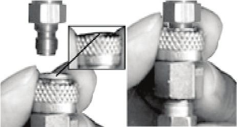
To avoid this danger, it is recommended (if your cylinder is not
already marked) that you use paint or nail polish to place a 3
mark (3) on the cylinder valve, and place another mark (4) on 4
the cylinder, in line with the #3 mark as shown.
Whenever you turn the cylinder during removal, watch the marks
3
on the cylinder and the cylinder valve to be sure that they rotate
together. If at any time these marks start to separate as shown
in the figure at right, the cylinder is starting to unscrew from the
cylinder valve and you must STOP and take the entire unit to
a “C5” certified airsmith for safe removal and/or repair.
NOTE: The cylinder valve should unscrew from the paintball
marker in about 3 or 4 full turns. If you finish the 4th full turn 4
and the cylinder valve is not unscrewed from the paintball
marker, STOP! Take the entire unit to a “C5” certified airsmith for safe removal and/or repair.
Locate a “C5” Certified Airsmith at www.paintball-pti.com. Whether you have a new or used
refillable air/CO2 cylinder, you are at risk if any of the following has occurred:
• The valve unit was replaced or altered after purchase.
• An anti-siphon device was installed.
• The valve unit was removed from the cylinder for any reason.
• Any modification was done to the refillable air/CO2 cylinder.
If any of these conditions has occurred, take your air/CO2 cylinder to a “C5” Certified Airsmith
for inspection or contact the cylinder manufacturer.
TP04225 Ver. 02/15 23E
N Air/CO2 Cylinder Safety Tips
G SAFETY TIPS to ensure that your air/CO2 cylinder is safe for play:
L • Improper use, filling, storage, or disposal of air/CO2 cylinder may result in property
I damage, serious personal injury or death.
S • Make sure that any maintenance or modification to any air/CO2 cylinder is done by
H a qualified professional, such as a “C5” certified airsmith.
• Installing an anti-siphon device is dangerous. However, if one is already installed on
your air or CO2 cylinder or is desired, it is critical that your cylinder be checked by,
or the device installed by, a qualified professional.
• All air/CO2 cylinders must be filled only by properly trained personnel.
• Cylinder valves must be installed only by properly trained personnel.
• Do not overfill a cylinder! Never exceed the air/CO2 cylinder’s capacity.
• Do not expose pressurized air/CO2 cylinder to temperatures exceeding 130 degrees
Fahrenheit (55 degrees Celsius).
• Do not use caustic cleaners or strippers on the air/CO2 cylinder or cylinder valve
and do not expose to corrosive materials.
• Do not modify the air/CO2 cylinder in any way. Never try to disassemble the cylinder
valve from the air/CO2 cylinder.
• Any air/CO2 cylinder that has been exposed to fire or heated to a temperature
of 250 degrees Fahrenheit (121 degrees Celsius) or more must be destroyed by
properly trained personnel.
• Use appropriate gas for your cylinder. Only use CO2 in a CO2 cylinder and only use
compressed air in a compressed air cylinder.
• Keep all cylinders out of the reach of children.
• The Air or CO2 cylinder should be inspected and hydrostatically retested at least
every 5 years by a DOT licensed agency.
• Keep exposed skin away from escaping gas when installing or removing air/CO2, or
if the marker or air/CO2 is leaking. Compressed air and CO2 gasses are very cold,
and can cause frostbite under certain conditions.
NOTE: Locate a “C5” certified airsmith at www.paintball-pti.com.
Repairing Air/CO2 Cylinder Leaks
The most common leak occurs from a bad air/CO2 cylinder valve O-ring. To replace a valve
O-ring you must first remove the bad O-ring and then install a new one. This O-ring is located
on the tip of your air/CO2 valve. The best valve O-rings are made of urethane. Urethane
O-rings are not affected by high air/CO2 pressures. These may be purchased from Tippmann
or your local paintball dealer.
NOTE: If a new air/CO2 valve O-ring does not resolve an air/CO2 leak, do not attempt to
repair the air/CO2 cylinder. Contact Tippmann Sports, LLC, your local paintball dealer, or a
“C5” Certified Airsmith.
24 TP04225 Ver. 02/15You can also read