INSTRUCTIONS FOR PREPARING ALUMACORE, ADSS, LOOSE TUBE, HEXACORE, CENTRACORE AND MINICORE FIBER OPTIC CABLES IN THE SB01 SPLICE ENCLOSURE - AFL GLOBAL
←
→
Page content transcription
If your browser does not render page correctly, please read the page content below
Installation Instructions
                                                       INS-ACA124

                    Instructions for Preparing

   AlumaCore, ADSS, Loose Tube, HexaCore,

CentraCore and MiniCore Fiber Optic Cables

                  in the SB01 Splice Enclosure

www.AFLglobal.com or 800-866-7385
                                    i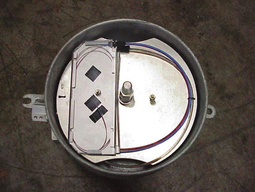
Installation
SB01 Splice
Instructions
Enclosure
Installation Instructions
INS-ACA124
TABLE OF CONTENTS
Instructions for Preparing AFL AlumaCore OPGW in Instructions for Preparing AFL HexaCore, CentraCore
the SB01 Splice Enclosure and MiniCore OPGW in the SB01 Splice Enclosure
Table of Contents . . . . . . . . . . . . . . . . . . . . . . . . . . . . . . . . . . 3 Table of Contents . . . . . . . . . . . . . . . . . . . . . . . . . . . . . . . . . . . 30
List of Materials. . . . . . . . . . . . . . . . . . . . . . . . . . . . . . . . . . . . 4 List of Materials . . . . . . . . . . . . . . . . . . . . . . . . . . . . . . . . . . . . 31
Purpose of Installation. . . . . . . . . . . . . . . . . . . . . . . . . . . . . . . 4 Purpose of Installation. . . . . . . . . . . . . . . . . . . . . . . . . . . . . . . . 32
Scope . . . . . . . . . . . . . . . . . . . . . . . . . . . . . . . . . . . . . . . . . . . 4 Scope. . . . . . . . . . . . . . . . . . . . . . . . . . . . . . . . . . . . . . . . . . . . 32
Precautions. . . . . . . . . . . . . . . . . . . . . . . . . . . . . . . . . . . . . . . 5 Precautions. . . . . . . . . . . . . . . . . . . . . . . . . . . . . . . . . . . . . . . . 32
Cable Preparation . . . . . . . . . . . . . . . . . . . . . . . . . . . . . . . . . . 5 Cable Preparation at Towers . . . . . . . . . . . . . . . . . . . . . . . . . . . 32
Cable to Splice Box Preparation . . . . . . . . . . . . . . . . . . . . . . . . 7 Preparation of the Splice Enclosure . . . . . . . . . . . . . . . . . . . . . . 33
Anchoring the Optical Units. . . . . . . . . . . . . . . . . . . . . . . . . . . 8 Securing the Optical Ground Wire Sample . . . . . . . . . . . . . . . . . 33
Optical Unit Preparation. . . . . . . . . . . . . . . . . . . . . . . . . . . . . . 9 HexaCore:
Splicing Fibers. . . . . . . . . . . . . . . . . . . . . . . . . . . . . . . . . . . . 12 Removal of Strands – Stranded Stainless Steel Tube Designs. . . 34
Installing Mounting Plate to Splice Box. . . . . . . . . . . . . . . . . . 13 CentraCore:
Sealing the Splice Box . . . . . . . . . . . . . . . . . . . . . . . . . . . . . . 14 Removal of Strands – SS Tube in Aluminum Pipe Designs. . . . . 35
Removal of Stainless Steel Tubes . . . . . . . . . . . . . . . . . . . . . . . . 36
Instructions for Preparing ADSS and Unarmored Loose Placement of the Transition Tubing. . . . . . . . . . . . . . . . . . . . . . . 38
Tube Cable in the SB01 Splice Enclosure Identifying Fiber Groups . . . . . . . . . . . . . . . . . . . . . . . . . . . . . . 38
Table of Contents . . . . . . . . . . . . . . . . . . . . . . . . . . . . . . . . . 18 Cleaning the Optical Units. . . . . . . . . . . . . . . . . . . . . . . . . . . . . 39
List of Materials. . . . . . . . . . . . . . . . . . . . . . . . . . . . . . . . . . . 19 Placement of the Transition Tubing. . . . . . . . . . . . . . . . . . . . . . . 39
Purpose of Installation. . . . . . . . . . . . . . . . . . . . . . . . . . . . . . 19 Placement of Optical Fibers in Transition Tubing/Trays
Scope . . . . . . . . . . . . . . . . . . . . . . . . . . . . . . . . . . . . . . . . . . 20 (12F Tray Application) . . . . . . . . . . . . . . . . . . . . . . . . . . . . . . . 40
Precautions. . . . . . . . . . . . . . . . . . . . . . . . . . . . . . . . . . . . . . 20 Optical Unit Preparation . . . . . . . . . . . . . . . . . . . . . . . . . . . . . . 41
Cable Preparation . . . . . . . . . . . . . . . . . . . . . . . . . . . . . . . . . 20 Splicing Fibers. . . . . . . . . . . . . . . . . . . . . . . . . . . . . . . . . . . . . . 42
Cable to Splice Box Preparation . . . . . . . . . . . . . . . . . . . . . . . 22 Installing Mounting Plate within the Splice Box . . . . . . . . . . . . . 43
Anchoring the Optical Units. . . . . . . . . . . . . . . . . . . . . . . . . . 23 Sealing the Splice Box. . . . . . . . . . . . . . . . . . . . . . . . . . . . . . . . 44
Optical Unit Preparation. . . . . . . . . . . . . . . . . . . . . . . . . . . . . 24 Appendix A. . . . . . . . . . . . . . . . . . . . . . . . . . . . . . . . . . . . . . . . 45
Splicing Fibers. . . . . . . . . . . . . . . . . . . . . . . . . . . . . . . . . . . . 25
Installing Mounting Plate to Splice Box. . . . . . . . . . . . . . . . . . 26 Instructions for Preparing ST1-72 Fiber Splice Tray
Sealing the Splice Box . . . . . . . . . . . . . . . . . . . . . . . . . . . . . . 27 in the SB01 Splice Enclosure
Table of Contents . . . . . . . . . . . . . . . . . . . . . . . . . . . . . . . . . . . 48
Tray Description. . . . . . . . . . . . . . . . . . . . . . . . . . . . . . . . . . . . . 49
Maximum Fiber Capacity. . . . . . . . . . . . . . . . . . . . . . . . . . . . . . 49
ADSS or Loose Tube Installation. . . . . . . . . . . . . . . . . . . . . . . . . 50
Stainless Steel Tube Installation. . . . . . . . . . . . . . . . . . . . . . . . . 51
Routing of Optical Fibers. . . . . . . . . . . . . . . . . . . . . . . . . . . . . . 52
Fiber Splice Sleeves. . . . . . . . . . . . . . . . . . . . . . . . . . . . . . . . . . 52
Closing the ST1-72 Tray. . . . . . . . . . . . . . . . . . . . . . . . . . . . . . . 53
Routing and Securing the ST1-72 Tray . . . . . . . . . . . . . . . . . . . . 53
Removing the ST1-72 Tray. . . . . . . . . . . . . . . . . . . . . . . . . . . . . 54
www.AFLglobal.com or 800-866-7385 5.18.2021
ii
AlumaCore OPGW
                                                                                        Installation Instructions
                                                                                                     INS-ACA124

                    Instructions for Preparing

       ALUMACORE OPTICAL GROUND WIRE

              IN THE SB01 SPLICE ENCLOSURE

                   ATTENTION:
                   The SB01 Splice Enclosure now includes a lid gasket that does not require RTV application.
                   Do not apply RTV to the gasket when sealing the SB01 Splice Enclosure. See Section 10
                   (page 14) for updated instructions.

                   NOTE:
                   EXCEPT AS MAY BE OTHERWISE PROVIDED BY CONTRACT, THESE DRAWINGS AND/OR
                   SPECIFICATIONS ARE THE PROPERTY OF AFL, ARE ISSUED IN STRICT CONFIDENCE, AND
                   SHALL NOT BE REPRODUCED OR COPIED OR USED AS THE BASIS FOR MANUFACTURE OR
                   SALE OF PRODUCT WITHOUT PERMISSION.

                   CERTAIN INFORMATION SUCH AS THE DATA, OPINIONS OR RECOMMENDATIONS SET FORTH
                   HEREIN OR GIVEN BY AFL REPRESENTATIVES, IS INTENDED AS A GENERAL GUIDE ONLY.
                   EACH INSTALLATION OF OVERHEAD ELECTRICAL CONDUCTOR, UNDERGROUND ELECTRICAL
                   CONDUCTOR, AND/OR CONDUCTOR ACCESSORIES INVOLVES SPECIAL CONDITIONS
                   CREATING PROBLEMS THAT REQUIRE INDIVIDUAL SOLUTIONS AND, THEREFORE, THE
                   RECIPIENT OF THIS INFORMATION HAS THE SOLE RESPONSIBILITY IN CONNECTION WITH
                   THE USE OF THE INFORMATION. AFL DOES NOT ASSUME ANY LIABILITY IN CONNECTION
                   WITH SUCH INFORMATION.

www.AFLglobal.com or 800-866-7385                                            © 2011, AFL, all rights reserved. INS-ACA034, Revision 3, 5.18.2021
                                                                                               Specifications are subject to change without notice.
                                                         1
AlumaCore OPGW
                                                   Installation Instructions
                                                                INS-ACA124

THE SB01 SPLICE ENCLOSURE NOW
INCLUDES A LID GASKET THAT DOES
   NOT REQUIRE RTV APPLICATION.

DO NOT APPLY RTV TO THE GASKET
   WHEN SEALING THE SB01 SPLICE
                               ENCLOSURE.

            SEE SECTION 10 (PAGE 14)
       FOR UPDATED INSTRUCTIONS.

www.AFLglobal.com or 800-866-7385       © 2011, AFL, all rights reserved. INS-ACA034, Revision 3, 5.18.2021
                                                          Specifications are subject to change without notice.
                                    2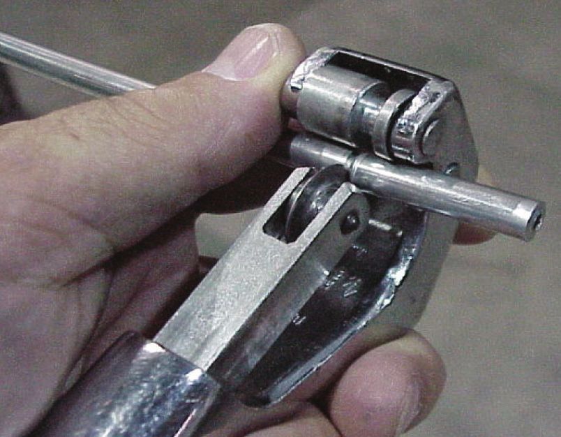
AlumaCore OPGW
                                                                Installation Instructions
                                                                             INS-ACA124

TABLE OF CONTENTS
CONTENTS                                  PAGE NO.
List of Materials                            4
Purpose of Installation                      4
Scope                                        4
Precautions                                  5
Cable Preparation                            5
Cable to Splice Box Preparation              7
Anchoring the Optical Units                  8
Optical Unit Preparation                     9
Splicing Fibers                             12
Installing Mounting Plate to Splice Box     13
Sealing the Splice Box                      14

www.AFLglobal.com or 800-866-7385                    © 2011, AFL, all rights reserved. INS-ACA034, Revision 3, 5.18.2021
                                                                       Specifications are subject to change without notice.
                                          3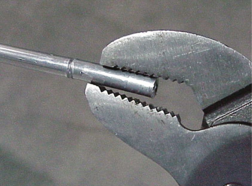
AlumaCore OPGW
                                                                                                                   Installation Instructions
                                                                                                                                INS-ACA124

List of Materials
     ITEM    DESCRIPTION                                                                                  QTY
             Splice Box (consisting of the following):
              Splice Box Body                                                                              1
              CSM Termination Eye Bolt                                                                   2 or 4
              Center Shaft                                                                                 1
              Cover Gasket                                                                                 1
              Connector Assemblies (consisting of the following items for 1 connector):                  2 or 4
      1
                 Connector Body                                                                            1
                 Cable Retainer                                                                            1
                 Nut Retainer                                                                              1
                 Entry Bushing                                                                             1
                 Set Screw – 5/16 – 18 UNC                                                                 2
                 O-Ring                                                                                    1
             Organizer Tray Assembly (consisting of the following items for 1 tray):                     2 to 8
              Tray                                                                                         1
      2       Cover                                                                                        1
              Splice Protector Holders (6 Splices / Holder)                                                2
              Manifold (MCI Tray Only)                                                                     1
       3     Splice Box Cover                                                                              1
       4     RTV – 108 Adhesive                                                                            1
       5     Spanner Nut or Hex Nut                                                                        1
       6     O-Ring or Self-Sealing Washer                                                                 1
       7     Retaining Rings                                                                               2
       8     Tension Screw                                                                               0 to 4
       9     Tension Nut                                                                                 0 to 4
      10     Humi – Sorb                                                                                   1
      11     Range-Taking Flanged Sleeve (used with FRP strength member)                                 0 to 4
      12     Mounting Plate                                                                                1
      13     Slotted Sleeve (used with OPT/GW FRP strength member)                                       0 to 4
      14     Spacer                                                                                        1
      15     Splice Protector Sleeves                                                                   10 to 56

Remove all loose parts, top retaining ring, spacer, mounting plate with tray assemblies from the box. Confirm all parts are present (see List of Materials
above), then place in a convenient location.
Please see supplemental instruction sheet for ST1-72 Tray installation instructions.

Items Supplied by Customer:
• Lag screws and washers (1/2 in. dia.) or hardware for attachment of assembly to pole or tower
• Silicone sealant for splice protection
• Splicer equipment

1.0 Purpose of Installation
The purpose of installing an Optical Ground Wire (OPGW) into a splice box is to connect one OPGW to another, and protect the connection in a sealed enclosure.

2.0 Scope
This document describes and illustrates the installation of Optical Ground Wire into the AFL SB01 splice box. This Splice Box has the following advantages:
1.    Capable of storing 25 to 40 feet of optical units per cable inside of the splice box for immediate or future splicing.
2.    The SB01 splice box can be pre-mounted because of its internal unit storage capacity. Typically the Splice Box is mounted to the pole or tower 15 to
      25 ft. (4.5 to 7.6 meters) from the ground.
3.    Creates a neater installation of the routing of the OPGW cables into the SB01 splice box. This eliminates the necessity of coiling extra OPGW cable
      onto the pole or tower.

www.AFLglobal.com or 800-866-7385                                                                       © 2011, AFL, all rights reserved. INS-ACA034, Revision 3, 5.18.2021
                                                                                                                          Specifications are subject to change without notice.
                                                                               4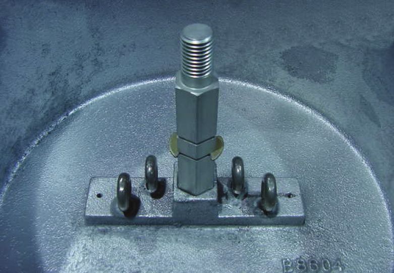
AlumaCore OPGW
                                                                                                                 Installation Instructions
                                                                                                                              INS-ACA124

3.0 Precautions
3.1    Health
       Optical fibers are very thin, fragile and sharp. Therefore, careful handling is required to avoid either damage to the delicate glass fibers, or more
       importantly, injury to the technician or bystander. Small fiber scraps should be deposited on strips of adhesive tape, placed in a bottle or vinyl bag
       and properly disposed. Do not eat, or drink when working with optical fibers as small pieces of glass may inadvertently be ingested. Never look
       directly at the end of a fiber unless certain that no Laser Light is being transmitted through the fiber.

3.2    Work Environment
       Handle optical fiber and fiber cable carefully, taking care to impose no damage by physical shock or sharp bends. During the actual splicing, care
       must be taken to keep hands and work area clean in order that the fibers may be kept clean. Dirty fibers mean poor splices! Keep all tools and
       equipment in their proper cases or storage pouches when not in use. Consideration should be given to the work area in which the Isolator will be
       organized. A clean, snag free horizontal surface is necessary.

4.0 Cable Preparation
4.1    After the stringing procedure, the ends of the optical unit(s) must be located. It is recommended that this occur prior to the cable being cut free
       from the payoff to ensure proper length remains for splicing. In some OPGW designs there could be some pull back of the optical unit(s) during
       the stringing installation. “Pullback” is a term used when the optical unit(s) or core appears to migrate inside the pipe due to elongation of the
       metallic components during the stringing procedure. When this happens, the core must be located so that the proper amount of optical unit(s) is
       available for the installation. Cut back 3-5 feet at a time until the optical unit(s) is found.

4.2    Form the OPGW cables into drip loops where they will enter the splice box. Mark the individual cables at these points. These Marks will
       be referenced as mark “A”. Mark “A” is eventually where the outer strands of the OPGW cables will enter the splice box. The diameter of
       the drip loops should be 30 x the Diameter of the OPGW or not less than 15 inches for a cable that is less than or equal to 0.5 inches in
       diameter (See Fig. 1).

       Fig. 1                                           SPLICE BOX IS
                                                        NORMALLY MOUNTED
                                                        15-25 FT. ABOVE
                                                        GROUND.

                                                                          “A” MARK OUTER
                                                                           STRANDS HERE
                    “B” CABLE
                      DRIP

                                                              15-25 FT.

                    GROUND                                            FREE END
                     LEVEL

4.3    Measure 30 feet from each individual OPGW cable mark “A” toward the Free End. Mark and cut the cables at this point. This will give 30
       feet of optical units for splicing. Unlay the wire strands from the free end about 1 foot back. Score the pipe with a tubing cutter. Do not
       cut completely through the pipe. Gently flex the pipe until it breaks. Cut the optical units between the sections of pipe that have been
       separated. This step is necessary so that the optical unit(s) will be able to move freely within the pipe when the pipe is removed.

NOTE: These measurements are based on the splice box being mounted 20 feet on the structure.

www.AFLglobal.com or 800-866-7385                                                                     © 2011, AFL, all rights reserved. INS-ACA034, Revision 3, 5.18.2021
                                                                                                                        Specifications are subject to change without notice.
                                                                             5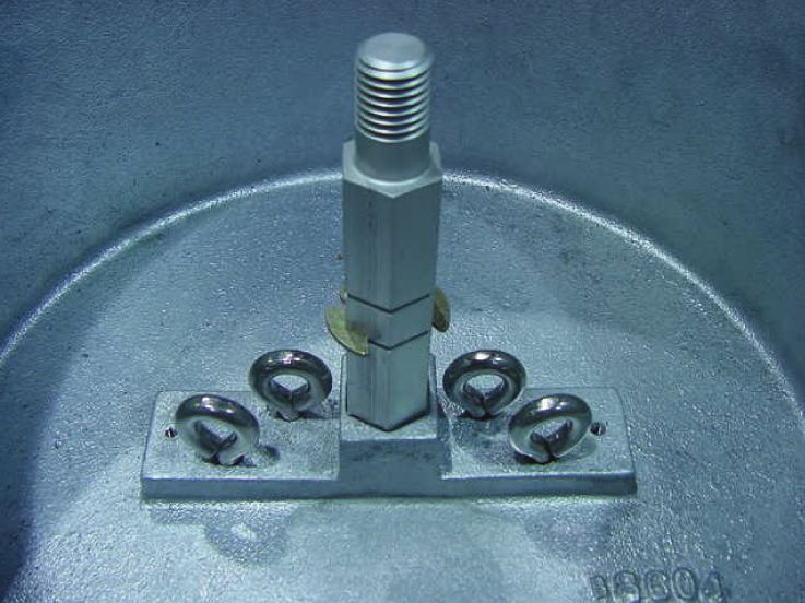
AlumaCore OPGW
                                                                                                                    Installation Instructions
                                                                                                                                 INS-ACA124

4.4     Apply electrical tape 12 inches behind mark “A” (See Fig. 2), THEN PREPARE THE OPGW CABLES ONE AT A TIME. Starting at steps 4.1 to 4.3. Cut
        the outer strands at the 2-foot mark, which is 24 inches from the “A” mark. Be careful not to damage or cut the pipe.

                                                   MEASURE FROM MARK "A" 30 FT. TOWARD
                                                     THE FREE END ON ALL OPGW CABLES

      Fig. 2           ELECTRICAL                 “A”                         2 FT.           FREE END OF CABLE
                          TAPE                   MARK                         MARK

                                    12"                          24"

NOTE: A tie-wrap can be used in place of electrical tape.

4.5     Once all of the marks have been established, insert a screwdriver in between the outer strands at the two-foot mark on one of the OPGW cables
        being careful not dent the pipe with screwdriver. Pry up one strand at a time and cut it. Then unlay the strand back to the electrical tape. Cut each
        strand at the Mark “A” (See Fig. 3a and 3b).

      Fig. 3a

                           ELECTRICAL             “A” MARK                                               ELECTRICAL
                              TAPE                                                                          TAPE

                                          12"

                                                    “A” MARK                   ALUMINUM PIPE
      Fig. 3b              ELECTRICAL           CUT HERE LEAVING                                         ELECTRICAL
                              TAPE                 NO BURRS                                                 TAPE

                                          12"

                                                                                                  REMOVE SECTION
                                                                                                    OF STRANDS

4.6     Measure 1 3/4 inches from the "A" mark. Using a felt marker pen, make a mark on the aluminum pipe. Then score the aluminum pipe with small pipe
        cutter. Try 2 or 3 rotational passes around the pipe first. Then try to bend the pipe back and forth. If the pipe does not move easily, try a few more
        passes. Do not score too deeply or completely through the pipe. If unsure, cut a small piece of pipe, 2 feet from the free end of the cable and practice
        cutting the pipe. The number of rotational passes can vary depending on the pipe size and design of the cable (See Fig. 4).

                                                                               ALUMINUM PIPE
      Fig. 4                         ELECTRICAL                                                 ELECTRICAL
                                                                    “A” MARK
                                        TAPE                                                       TAPE

                                                                             1 3/4"

                                                          12"                       24"

www.AFLglobal.com or 800-866-7385                                                                        © 2011, AFL, all rights reserved. INS-ACA034, Revision 3, 5.18.2021
                                                                                                                           Specifications are subject to change without notice.
                                                                                6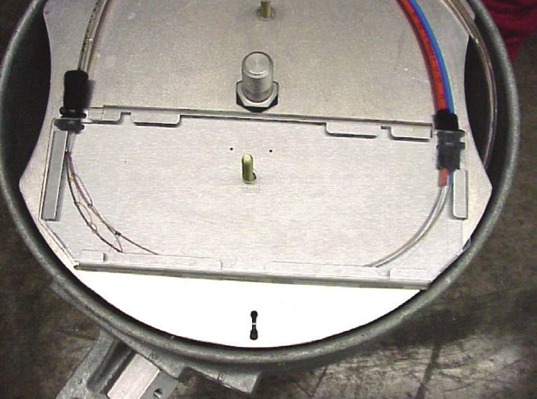
AlumaCore OPGW
                                                                                                                    Installation Instructions
                                                                                                                                 INS-ACA124

4.7     The pipe may now be broken by bending it back and forth gently and by not more than 10 degrees (See Fig. 5).
                                                                       24"
        Fig. 5

                                                                                                                                    10°

                                                                ALUMINUM PIPE

4.8     Slide the outer strands with pipe intact about 2 feet toward the free end of the cable. While holding the cable pull the optical units completely out of
        the pipe by pulling toward the tower. Be careful not to kink the optical unit(s) (See Fig. 6).

        Fig. 6                      PULL OPTICAL UNITS                                                PULL TOWARD
                                    TOWARD THE TOWER                    2 FT. (0.62 M)                THE FREE END

                                                                      ALUMINUM PIPE

4.9     Immediately tape the end of the optical units when the end clears the aluminum pipe. This will hold the core intact for ease in performing the
        next steps.

5.0 Cable to Splice Box Preparation
The section will explain how to install the cable into the splice box. This should be performed when the individual OPGW cable has been properly prepared.

5.1     After the individual OPGW end has been prepared slide the cable retainer over the optical unit(s) and over all outer-strands of wires. Then place a
        bead of RTV silicone on the wire tips and around the pipe (See Fig. 7).

        Fig. 7

                                                                                                         OPTICAL UNIT

                                                                                    BEAD OF RTV

5.2     Below (See Fig. 8) is a cross-section of the cable connection inside the splice box plus a three-step procedure for securing the cable to the splice
        box. Do not unwrap the binder tape and expose the yarn and unit(s) at this time. (NOTE: Use the ports on the right side of the splice box first,
        when two cables are being spliced.)

                                          CONNECTOR BODY
        Fig. 8                                                                              RETAINING NUT
                       CABLE RETAINER

                                   OPGW                    ALUMINUM PIPE

                                                                                                         OPTICAL UNITS
                                           SET SCREWS                                ENTRY BUSHING

www.AFLglobal.com or 800-866-7385                                                                        © 2011, AFL, all rights reserved. INS-ACA034, Revision 3, 5.18.2021
                                                                                                                           Specifications are subject to change without notice.
                                                                                7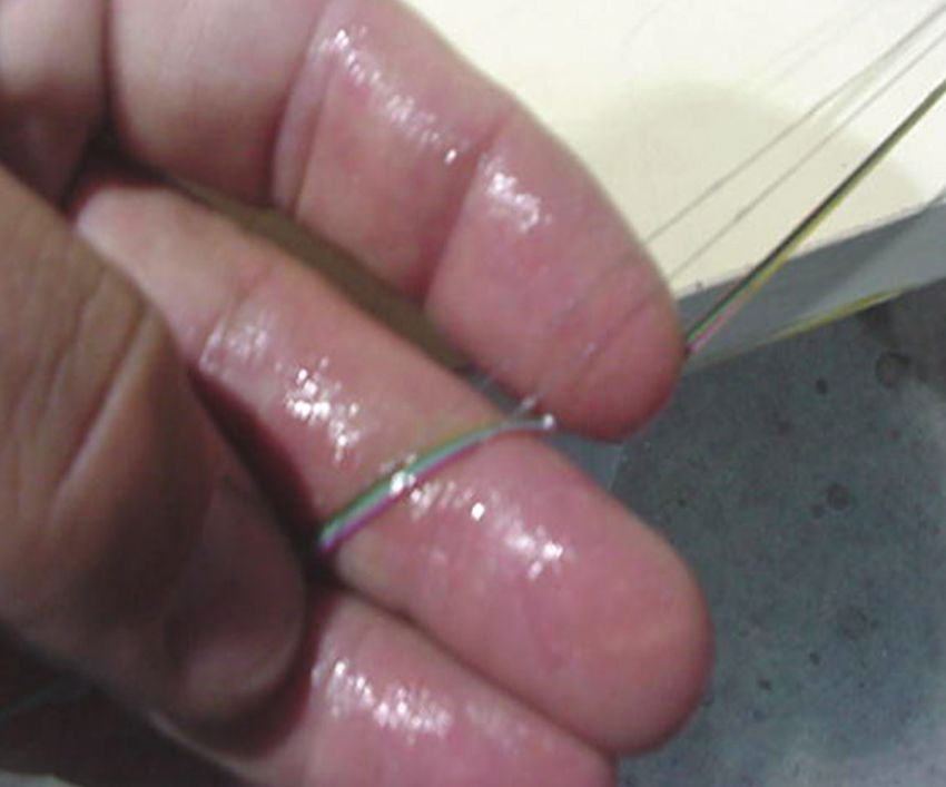
AlumaCore OPGW
                                                                                                                      Installation Instructions
                                                                                                                                   INS-ACA124

5.3     Feed the optical units from the OPGW cable through the connector body and entry bushing. Route the optical unit(s) so that they lay on the center
        shaft of the splice box during the feeding process. This will keep the optical unit(s) from kinking.

5.4     After all of the unit(s) have been fed into the enclosure, insert the OPGW cable with the cable retainer into the connector body of the splice box. Make
        sure that the cable retainer is aligned properly and inserted completely. Tighten setscrews.

5.5     Each of the fiber unit(s) should be supported and attached with tape to the outer diameter of the splice enclosure (See Fig. 9) as soon as the OPGW
        cable has been secured into the connector body. This will secure the optical unit(s) to the splice box and prevent them from kinking.

5.6     If a Dielectric Cable is being spliced, the connector body may have a conduit fitting attached to it. To verify that the cable retainer on the dielectric
        cable has been aligned properly, remove the top Allen (hex socket head) screw and visually align and tighten setscrews. This type of Splice Box
        configuration (OPGW spliced to a dielectric cable) should be located on the TAKE-OFF structures or designated splice locations where this type of
        splice box applies.

5.7     Repeat all of the previous steps for the remaining OPGW cables that are to be installed into this particular splice location. Remember to prep only one
        cable at a time.

6.0 Anchoring the Optical Units
6.1     Place a piece of electrical tape on the individual optical units, 14 to 18 inches from the entry bushing of the splice box. Working with one optical
        unit at a time, cut the binder tape at this mark, on the entry bushing side. Unwrap the binder tape back to the entry bushing and cut the binder
        tape. Cut the yarn at the electrical tape and use the yarn to anchor the optical unit by threading the yarn through the eyebolt and tying in a series
        of half hitches. Make sure that the yarn is tied off in line and to the eyebolt in the proper position from where the individual OPGW cable enters
        the splice box. If the cable does not contain yarn, the central strength member should be anchored into the box. Repeat the previous steps for the
        remaining OPGW cable(s). Tape the optical units together after they have been secured to the eye-bolts (See Fig. 9).

        Fig. 9
                       30 FT. (TO FREE
                       END OF CABLE)                                                     TAPE

                                                                                                 TIE OFF YARN OR
                                                                                                 CENTRAL STRENGTH MEMBER

                                                                                                 ROUTE OPTICAL UNITS
                                                                                                 BEHIND YARN

           ENTRY BUSHING SEALS
           AROUND THE PIPE
                                                                                  REMOVE BINDER TAPE
                                                                                  AT THIS POINT

NOTE: There should be 30 ft. of optical unit(s) prepped for each individual OPGW cable that is to be inserted into the Splice Box. The 30 ft. of optical unit(s) is
      divided into two sections:

        1. 20 ft. from box to ground, and
        2. 10 ft. for storing and splicing.

        Should the Splice Box be mounted at a different height, then adjust the amount of OPGW cable to be prepped, stored and spliced.

www.AFLglobal.com or 800-866-7385                                                                          © 2011, AFL, all rights reserved. INS-ACA034, Revision 3, 5.18.2021
                                                                                                                             Specifications are subject to change without notice.
                                                                                 8
AlumaCore OPGW
Installation Instructions
INS-ACA124
6.2 Temporarily tape the units to the top outside radius of the box (See Fig. 9). This will help support the units and prevent damage of the units at the
bushing. Also explained in section 5.5.
6.3 Tighten the retaining nut so that the bushing is sealed around the pipe.
6.4 Tape all of the optical units together every 2 feet. Stop taping the optical units 6 feet from the free end. Tape each individual group of optical unit(s)
up to 4 feet 10 inches from the free end. Remove the yarn and binder tape from the optical unit(s) along the 4 foot 10 inch section toward the free
end.
7.0 Optical Unit Preparation
7.1 Starting at the free end of one of the OPGW cables, separate the individual colored units one at a time by unlaying them back to the 4 foot 10
inch tape mark. (This only applies to the multiple unit configurations). Now proceed to the other OPGW units and repeat the same step
7.2 Mark the individual colored unit(s) 4 feet from the free end with a permanent marker. In case of multiple units, pair the like colored buffer tubes
together. (For example, take the blue units from each of the OPGW cables and match them up. Continue with orange to orange, green to green,
etc.).
For Tight Structure Type Alumacore, follow steps 7.3 to 7.4.
For Loose Tube Type Alumacore, follow steps 7.5 to 7.6.
7.3 Place the AFL sheath stripper on one of the blue units at the 4-foot mark with the arrow on the sheath stripper pointing toward the free end. Grip
down tightly and pull the sheath stripper in one continuous motion toward the free end. Remove the colored sheath.
7.4 Carefully remove the clear epoxy coating from the entire 4 feet by starting at the free end and peeling back. Slowly remove the fibers from the
fiberglass reinforced plastic central member (FRP). Count the fibers to make sure that all the fibers are identified before proceeding. Continue
separating the fibers for the remainder of the 4 feet. Cut the FRP as close as possible to the core of the optical unit without damaging any fibers.
Clean and remove the silicone from all the fibers. Proceed to step 7.7.
7.5 For loose tube units, using a buffer tube cutter, carefully score and snap the buffer tubes at the 4-foot mark, then gently pull the tube straight
away from the fibers.
7.6 If the buffer tubes contain 12 fibers or less, gently wipe them with a clean towel to remove the excess gel. Then clean them with an approved gel-
removing solvent. The fibers are ready to be loaded into the splice tray(s). Proceed to Step 7.7.
If the buffer tubes contain more than 12 fibers each, follow the below instructions pertaining to the colored thread binders.
7.6.1 Starting at the end closest to the stainless steel tube, separate the fibers until you identify one of the colored string binders (See Fig. 10).
7.6.2 Lightly pull on the binder until the bundle starts to separate from the other fibers.
7.6.3 Once a single bundle has been identified, inspect the bundle for the matching color prior to separating the fibers from the other bundles.
Once you have identified that both binders are around the same fiber group, separate the unit from the other fibers (See Fig. 11).
Fig. 10 Fig. 11
www.AFLglobal.com or 800-866-7385 © 2011, AFL, all rights reserved. INS-ACA034, Revision 3, 5.18.2021
Specifications are subject to change without notice.
9AlumaCore OPGW
Installation Instructions
INS-ACA124
7.6.4 Repeat steps 7.6.1 through 7.6.2 on each of the fiber bundles. Separate each group of bundled fibers to assure easy identification (See Fig. 12).
7.6.5 On each of the fiber bundles, confirm that the fibers meet the proper color code and specified fiber amount (See Fig. 13).
Fig. 12 Fig. 13
7.6.6 After all of the fiber bundles have been checked, return to the fiber end closest to the buffer tube. Separate and cut both string binders
approximately 12 inches from the buffer tube. Remove and dispose of the excess binder from the optical fibers (See Fig. 14). Take both
remaining binders and loosely loop it through itself to form a small slipknot around the bundle they mark. Repeat this process 4 to 5 times.
Cut the excess binder, approximately 1.5 inches above the knot (See Fig. 15).
Fig. 14 Fig. 15
7.6.7 Assure that each bundle is identifiable before continuing on to the to the next.
7.6.8 After all fiber bundles have been identified, clean each individual fiber group with a standard gel removal cleaner (See Figs. 16 and 17).
Fig. 16 Fig. 17
www.AFLglobal.com or 800-866-7385 © 2011, AFL, all rights reserved. INS-ACA034, Revision 3, 5.18.2021
Specifications are subject to change without notice.
10AlumaCore OPGW
Installation Instructions
INS-ACA124
7.7 After same color optical units have been stripped, cleaned, and separated, tape the like units together by placing a piece of double-back tape ¼
inch from the end of the outer jacket material of the optical units. Place the double-back tape units onto the splice tray and secure them to the
tray with tie wraps (see Fig. 18).
Fig. 18 OPTICAL UNITS TIE-WRAPS
CLEANED FIBERS
7.8 When cutting fibers to length, wrap the 4 feet of fibers of the inside units around the tray in a clockwise direction. Cut the fibers so that the spliced
section will fit into the splice protector sleeve holders. Be sure that the fibers are cut and positioned in color code order. Prepare the outside unit in the
same manner. The first six fibers will be shorter than the last six fibers in the outside unit. In the inside unit, the first six fibers will be longer than the last
six fibers, based on a 12-fiber unit design. Place the cover onto the splice tray making sure that all of the fibers are wrapped inside the tray (see Fig. 19).
Fig. 19 OPTICAL UNITS TIE-WRAPS
END OF OUTER JACKET
7.9 Prep all trays in the same manner as in detailed in Fig. 20 before any splicing is performed. (NOTE: The exact arrangement may vary due to fiber
count configurations.)
Fig. 20 CUTTING THE FIBERS TO LENGTH
OUTSIDE UNIT OUTSIDE UNIT
FIBERS 7-12 FIBERS 1-6
CUT FIBERS HERE
CUT FIBERS HERE
INSIDE UNIT
INSIDE UNIT FIBERS 1-6
FIBERS 7-12
Lay the fibers across their appropriate Splice Protector Holder and cut
the fibers at the mid-point of the Splice Protector Holder.
www.AFLglobal.com or 800-866-7385 © 2011, AFL, all rights reserved. INS-ACA034, Revision 3, 5.18.2021
Specifications are subject to change without notice.
11AlumaCore OPGW
Installation Instructions
INS-ACA124
8.0 Splicing Fibers
When splicing, follow these steps:
8.1 Splicing will be easier if the splice tray is level with the top of the splicer.
8.2 Lay out only enough fiber to cleave and place into the splicer.
8.3 Slide one splice protector sleeve over each of the fibers before making splices.
8.4 After splicing is completed and the splicing technician has accepted the splice, slide the splice protector over the spliced area and place in the tube
heater. Once the splice protector has cooled and has become rigid, place and center it into splice protector holder in the tray.
8.5 After all of the fibers have been spliced, protected and positioned, make sure that all fibers are stored on the inside of the splice tray. Place the splice
tray cover onto the splice tray. Secure the splice tray cover to the splice tray by wrapping both ends of the splice tray with electrical tape (See Fig. 20a).
8.6 If multiple splice trays are required, work only with one splice tray at a time.
8.7 Place the splice tray(s) on the mounting plate bolt. If multiple splice trays are present, be sure to stack all splice tray(s) on the same side of the
mounting plate. Place the tension nut on the bolt and tighten it down snug. This will keep the splice tray(s) secured to the mounting plate.
Fig. 20a FRONT VIEW
TIE-WRAP OVER THE FELT TO
SECURE THE OPTICAL UNITS
TO THE MOUNTING PLATE.
OPTICAL
UNITS
ELECTRICAL
TAPE
8.8 Place felt around the mylar tape on both units and tie-wrap as shown in Fig. 20a above.
www.AFLglobal.com or 800-866-7385 © 2011, AFL, all rights reserved. INS-ACA034, Revision 3, 5.18.2021
Specifications are subject to change without notice.
12AlumaCore OPGW
Installation Instructions
INS-ACA124
9.0 Installing Mounting Plate to Splice Box
9.1 Using felt around the mylar tape, secure the optical units to the back side of the mounting plate. Tie-wrap the optical units (snug) as shown in Fig. 20b.
9.2 Coil the optical units in a counter-clockwise direction on to the back side of the mounting plate. Coil just enough of the optical units so that the
mounting plate would lie on the ground. (The reason for this is to prevent a tremendous mechanical shock to the optical units in the event that the
technician drops the mounting plate while coiling the optical units as he climbs the tower.)
9.3 After coiling as much of the optical units (while on the ground tie-wrap the units snug, but not too tight), continue to coil the optical units around the
back side of the mounting plate about 1 inch from the edge until the splice box has been reached. Remove the temporary tape from the top front rim
of the splice box. Proceed to coil the small section of optical units in a counter-clockwise direction and by aligning and positioning the mounting plate
to the center shaft.
NOTE: Coiling the optical units should be done by rotating the mounting plate. This avoids twisting and stressing the fiber units (See Back View, below).
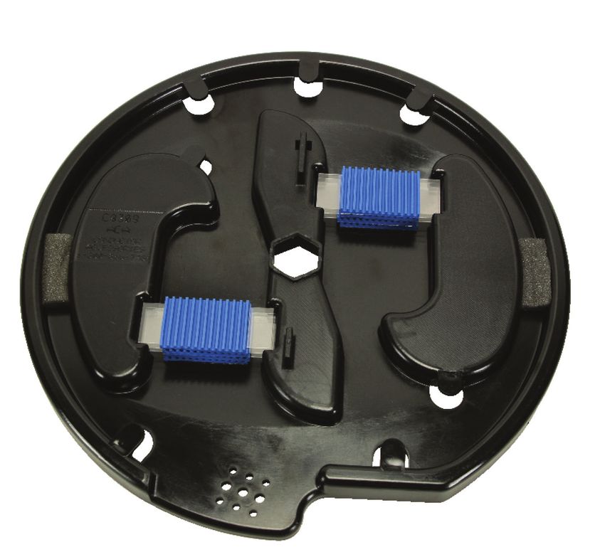
Fig. 20b BACK VIEW PLACE FELT ON
THE OPTICAL UNITS.
COIL OPTICAL UNITS
ONTO THE BACK SIDE
OF MOUNTING PLATE.
TIE-WRAP UNITS OVER
FELT TO THE BACK.
9.4 When all of the slack is coiled and stored behind the mounting plate, align the mounting plate and secure it to the center shaft by placing the spacer
on the center shaft, and installing the outside retaining “clip” ring. (See Fig. 21a on following page.)
www.AFLglobal.com or 800-866-7385 © 2011, AFL, all rights reserved. INS-ACA034, Revision 3, 5.18.2021
Specifications are subject to change without notice.
13AlumaCore OPGW
Installation Instructions
INS-ACA124
Fig. 21a Fig. 21b
SPLICE BOX
SPLICE BOX LID
MOUNTING
PLATE
SPACER SPANNER NUT
OUTSIDE OR HEX NUT
CENTER RETAINING
SHAFT CLIP RING
O-RING WITH RTV 108
OR SELF-SEALING
WASHER
SECURING
ACCUMULATE NUT
OPTICAL UNITS IN
THIS AREA BEHIND
MOUNTING PLATE
TRAY
ASSEMBLY
GASKET LID
GASKET
10.0 Sealing the Splice Box
10.1 Using alcohol ≥91% and a clean cloth, wipe down the inside groove (both sides) of the gasket and the inside of the splice box lid.
10.2 Place the gasket on the splice box with the beveled side on the lip of the splice box.
Fig. 22
10.3 Place the splice box lid on the splice box.
WITH SPANNER NUT
10.5 Place the O-Ring over shaft. Cover the O-Ring with RTV. Screw the spanner nut on the shaft.
10.6 Tighten the spanner nut on the center shaft until the lid bottoms out (typically 45 ft-lbs).
WITH JAM NUT
10.5 Place the self-sealing washer over the shaft. Screw the nut on the shaft.
10.6 Tighten the spanner nut on the center shaft until the lid bottoms out (typically 45 ft-lbs).
www.AFLglobal.com or 800-866-7385 © 2011, AFL, all rights reserved. INS-ACA034, Revision 3, 5.18.2021
Specifications are subject to change without notice.
14AlumaCore OPGW
Installation Instructions
INS-ACA124
Fig. 23 CONNECTOR ASSEMBLY FLANGED SLEEVE
(IF REQUIRED)
ENTRY BUSHING
SET SCREWS O-RING
RETAINING
CAP
RETAINING
NUT
CONNECTOR
BODY
WIRE
RETAINER
www.AFLglobal.com or 800-866-7385 © 2011, AFL, all rights reserved. INS-ACA034, Revision 3, 5.18.2021
Specifications are subject to change without notice.
15ADSS and Loose Tube Cable
Installation Instructions
INS-ACA124
Instructions for Preparing
ADSS AND UNARMORED LOOSE TUBE CABLE
IN THE SB01 SPLICE ENCLOSURE
ATTENTION:
The SB01 Splice Enclosure now includes a lid gasket that does not require RTV application.
Do not apply RTV to the gasket when sealing the SB01 Splice Enclosure. See Section 10
(page 27) for updated instructions.
NOTE:
EXCEPT AS MAY BE OTHERWISE PROVIDED BY CONTRACT, THESE DRAWINGS AND/OR
SPECIFICATIONS ARE THE PROPERTY OF AFL, ARE ISSUED IN STRICT CONFIDENCE, AND
SHALL NOT BE REPRODUCED OR COPIED OR USED AS THE BASIS FOR MANUFACTURE OR
SALE OF PRODUCT WITHOUT PERMISSION.
CERTAIN INFORMATION SUCH AS THE DATA, OPINIONS OR RECOMMENDATIONS SET FORTH
HEREIN OR GIVEN BY AFL REPRESENTATIVES, IS INTENDED AS A GENERAL GUIDE ONLY.
EACH INSTALLATION OF OVERHEAD ELECTRICAL CONDUCTOR, UNDERGROUND ELECTRICAL
CONDUCTOR, AND/OR CONDUCTOR ACCESSORIES INVOLVES SPECIAL CONDITIONS
CREATING PROBLEMS THAT REQUIRE INDIVIDUAL SOLUTIONS AND, THEREFORE, THE
RECIPIENT OF THIS INFORMATION HAS THE SOLE RESPONSIBILITY IN CONNECTION WITH
THE USE OF THE INFORMATION. AFL DOES NOT ASSUME ANY LIABILITY IN CONNECTION
WITH SUCH INFORMATION.
www.AFLglobal.com or 800-866-7385 © 2011, AFL, all rights reserved. INS-ACA035, Revision 1, 11.20.14
Specifications are subject to change without notice.
16ADSS and Loose Tube Cable
Installation Instructions
INS-ACA124
THE SB01 SPLICE ENCLOSURE NOW
INCLUDES A LID GASKET THAT DOES
NOT REQUIRE RTV APPLICATION.
DO NOT APPLY RTV TO THE GASKET
WHEN SEALING THE SB01 SPLICE
ENCLOSURE.
SEE SEALING THE SPLICE BOX
SECTION (PAGE 27)
FOR UPDATED INSTRUCTIONS.
www.AFLglobal.com or 800-866-7385 © 2011, AFL, all rights reserved. INS-ACA035, Revision 1, 11.20.14
Specifications are subject to change without notice.
17ADSS and Loose Tube Cable
Installation Instructions
INS-ACA124
TABLE OF CONTENTS
CONTENTS PAGE NO.
List of Materials 19
Purpose of Installation 19
Scope 20
Precautions 20
Cable Preparation 20
Cable to Splice Box Preparation 22
Anchoring the Optical Units 23
Optical Unit Preparation 24
Splicing Fibers 25
Installing Mounting Plate to Splice Box 26
Sealing the Splice Box 27
www.AFLglobal.com or 800-866-7385 © 2011, AFL, all rights reserved. INS-ACA035, Revision 1, 11.20.14
Specifications are subject to change without notice.
18ADSS and Loose Tube Cable
Installation Instructions
INS-ACA124
List of Materials
ITEM DESCRIPTION QTY
Splice Box (consisting of the following):
Splice Box Body 1
CSM Termination Eye Bolt 2 or 4
Center Shaft 1
Cover Gasket 1
Connector Assemblies (consisting of the following items for 1 connector): 2 or 4
1
Connector Body 1
Cable Retainer 1
Nut Retainer 1
Entry Bushing 1
Set Screw – 5/16 – 18 UNC 2
O-Ring 1
Organizer Tray Assembly (consisting of the following items for 1 tray): 2 to 8
Tray 1
2 Cover 1
Splice Protector Holders (6 Splices / Holder) 2
Manifold (MCI Tray Only) 1
3 Splice Box Cover 1
4 Spanner Nut or Hex Nut 1
5 O-Ring or Self-Sealing Washer 1
6 Retaining Rings 2
7 Tension Screw 0 to 4
8 Tension Nut 0 to 4
9 Humi – Sorb 1
10 Range-Taking Flanged Sleeve (used with FRP strength member) 0 to 4
11 Mounting Plate 1
12 Slotted Sleeve (used with OPT/GW FRP strength member) 0 to 4
13 Spacer 1
14 Splice Protector Sleeves 10 to 56
Remove all loose parts, top retaining ring, spacer, mounting plate with tray assemblies from the box. Confirm all parts are present (see List of Materials
above), then place in a convenient location.
Please see supplemental instruction sheet for ST1-72 Tray installation instructions.
Items Supplied by Customer:
• Lag screws and washers (1/2 in. dia.) or hardware for attachment of assembly to pole or tower
• Silicone sealant for splice protection
• Splicer equipment
1.0 Purpose of Installation
This document describes and illustrates the installation of ADSS and/or Unarmored Loose Tube Cable into the AFL (B8424) Premounted Splice Box.
www.AFLglobal.com or 800-866-7385 © 2011, AFL, all rights reserved. INS-ACA035, Revision 1, 11.20.14
Specifications are subject to change without notice.
19ADSS and Loose Tube Cable
Installation Instructions
INS-ACA124
2.0 Scope
This Splice Box has the following advantages:
1. Capable of storing a minimum of 30 ft. of optical unit per ADSS and/or Unarmored Loose Tube cable inside of the (B8424) Splice Box for immediate
or future splicing.
2. The (B8424) Splice Box can be premounted because of its internal unit storage capacity. Typically the Splice Box is mounted to the pole or tower 15-
25 ft. (6.1 meters) from the ground.
3. Creates a neater installation of the routing of cables into the (B8424) Splice Box. This eliminates the necessity of coiling of extra cable onto the pole
or tower.
3.0 Precautions
3.1 Health
Optical fibers are very thin, fragile, and sharp. Therefore, careful handling is required to avoid either damage to the delicate glass fibers or, more
importantly, injury to the technician or bystander. Small fiber scraps should be deposited on strips of adhesive tape, placed in a bottle or vinyl bag,
properly disposed. Do not eat or drink when working with optical fibers as small pieces of glass may inadvertently be ingested. Never look directly
at the end of a fiber unless certain that no Laser Light is being transmitted through the fiber.
3.2 Work Environment
Handle optical fiber and fiber cable carefully, taking care to impose no damage by physical shock or sharp bends. During the actual splicing, care
must be taken to keep hands and work area clean in order that the fibers may be kept clean. Dirty fibers mean poor splices! Keep all tools and
equipment in their proper cases or storage pouches when not in use. Consideration should be given to the work area in which the splice box will
be organized. A clean, snag free horizontal surface (protected from wind) is necessary.
4.0 Cable Preparation
4.1 After the stringing or pulling procedure there should be a minimum of a 100 ft. of ADSS and/or Unarmored Loose Tube cable from each pulling
direction at the tower. The 100 ft. of ADSS and/or Unarmored Loose Tube cable is measured from the base of the tower.
4.2 When marking the ADSS and/or Unarmored Loose Tube cable use yellow or contrasting color tape to ad in visibility. Form the ADSS and/or
Unarmored Loose Tube cable into drip loops where they will enter the connector body at the splice box. Mark the individual cables at these points.
These Marks will be referenced to as Mark “A”. (See Fig. 1.)
Fig. 1
SPLICE BOX IS NORMALLY
MOUNTED 15-25 FT.
ABOVE GROUND.
“A” MARK OUTER
“B” CABLE STRANDS HERE
DRIP
15-25 FT.
GROUND FREE END
LEVEL
FIBER OPTIC
UNDERGROUND
CABLE
www.AFLglobal.com or 800-866-7385 © 2011, AFL, all rights reserved. INS-ACA035, Revision 1, 11.20.14
Specifications are subject to change without notice.
20ADSS and Loose Tube Cable
Installation Instructions
INS-ACA124
4.3 Measure 30 feet from each individual ADSS and/or Unarmored Loose Tube cable from mark “A” toward the Free End. This will give 30 feet of
optical units for storage and splicing.
NOTE: These measurements are based on the splice box being mounted 20 feet on the structure.
4.4 From point “A” measure 2 3/4 inches toward the loose end of the cable and carefully ring cut the cable. The ring cut will point “B” (see Figs. 2 and
3). From the ring cut to the loose end of the cable remove the outside jacket/coating. Therefore, from the loose end, expose 4-6 inches of the rip
cord. Then, grip the rip cord and pull to point “B”. Remove the jacket/coating.
Fig. 2 Fig. 3
2 3/4"
POINT “A” POINT “A” POINT “B”
2 3/4"
POINT “B”
FIBER OPTIC
UNDERGROUND
CABLE
4.5 If Kevlar is present leave 20 inches from point “B” toward the loose end of the cable. Cut the Kevlar at this 20 inch mark and remove from that
point to the end of the cable. Should the ADSS or Loose Tube cable have a inside jacket measure from point “B” out 7 ft. toward the loose end of
the cable and mark with a contrasting tape (black may be poor choice). (See Fig. 4.) Call this new point, point “C”. Carefully ring cut at point “C”.
DO NOT CUT the rip cord or nick the fibers bearing tubes.
FREE END OF CABLE
Fig. 4
POINT POINT 20" OF POINT
“A” “B” ARAMID YARN “C”
7 FT.
This is for the removal of the inner jacket to the loose end of the cable. Therefore at the loose end of the cable, expose 4-6 inches of the rip cord, pull
this cord to Point “C” and remove this jacket.
4.6 Now remove the mylar tape and string binders. Remove short sections of the string binders from the loose end (a mono carbon cleaner works well).
www.AFLglobal.com or 800-866-7385 © 2011, AFL, all rights reserved. INS-ACA035, Revision 1, 11.20.14
Specifications are subject to change without notice.
21ADSS and Loose Tube Cable
Installation Instructions
INS-ACA124
4.7 After all of the binders are removed, carefully roll out the FRP Central Member. Be very careful not to collapse the fiber bearing tubes. Remove the RFP
about 1/2" (± 1/8") or 1/2" (± 5/8") from point “C”. Clean and dry the area around point “C”. (See Fig. 5.)
Fig. 5
POINT “C”
NO FRP OR
STRING BINDER
END OF CABLE
5.5 - 6 FT.
4.8 With the FRP member removed and point “C” dry, retape this area in a spiral manner with a 2 ½” to 3” vinyl tape i.e., from point “C” to about 5.5 to
6 feet from the cable end. (See Fig. 6.)
Fig. 6
POINT “C”
START TAPE
END TAPE
END OF CABLE
5.5 - 6 FT.
5.0 Cable to Splice Box Preparation
The section will explain how to install the cable into the splice box. This should be performed when the individual ADSS and/or Unarmored Loose Tube cable
has been properly prepared.
5.1 Position the proper size cable retainer against the tape at point “A” and put a wrap or two of tape at both ends of the cable retainer on the cable
only.
5.2 Install this cable into the splice enclosure until the cable retainer is properly positioned and locked in the connector body. Always be careful to
support the cable while inserting it into the splice enclosure so that the tubes are not damaged in any way. (See Fig. 7).
Fig. 7
OPTICAL UNIT
CABLE RETAINER
5.3 This procedure must be done to each of the type of cable installed in the enclosure.
www.AFLglobal.com or 800-866-7385 © 2011, AFL, all rights reserved. INS-ACA035, Revision 1, 11.20.14
Specifications are subject to change without notice.
22ADSS and Loose Tube Cable
Installation Instructions
INS-ACA124
5.4 Fig. 8 below is a cross section of the cable connection inside the splice box plus a three step procedure for securing the cable to the splice box.
CONNECTOR BODY
Fig. 8 RETAINING NUT
CABLE RETAINER
SPLICE BOX WALL
ADSS OR
UNARMORED OPTICAL UNITS
LOOSE TUBE SET SCREWS ENTRY BUSHING
5.5 Feed the optical units from the cable, through the connector body and entry bushing. Route the optical unit(s) so that they lay on the center shaft
of the splice box during the feeding process. This will keep the optical unit(s) from kinking.
5.6 After all of the unit(s) have been fed into the enclosure insert the cable with the cable retainer into the connector body of the splice box. Make
sure that the cable retainer is aligned properly and inserted completely. Tighten set screws.
5.7 Each fiber unit(s) should be supported and attached with duct tape to the outer diameter of the splice enclosure (see fig. 9) as soon as the cable
has been secured into the connector body. This will secure the optical unit(s) to the splice box and prevent them from kinking.
5.8 If Dielectric Cables are being used, the connector body may have a conduit fitting attached to it. To verify the cable retainer on the Dielectric cable
has been aligned properly, remove the top allen screw and visually align and tighten set screws.
5.9 Repeat all of these steps for the remaining cables that are to be installed into this particular splice location.
Remember to prep only one cable at a time.
6.0 Anchoring the Optical Units
6.1 To anchor the optical thread the yarn through the eye-bolt and tying in a series of half-hitches. Make sure that the yarn is tied off in line and to
the eye bolt in the proper position from where the individual cable enters the splice box. Repeat the following steps for the remaining cable(s).
Tape the optical units together after they have been secured to the eye-bolts. (See Fig. 9.)
Fig. 9
30 FT. (TO FREE
END OF CABLE) DUCT TAPE
TIE OFF
THE YARN
ROUTE OPTICAL UNITS
BEHIND YARN
ENTRY BUSHING
RETAINING
NUT
NOTE: There should be 50 ft. of optical unit(s) prepped for each individual cable that is to be inserted into the Splice Box. The 50 ft. of optical unit(s) is
broken down into two sections:
1. 20 ft. from splice box to ground, and
2. 30 ft. for storing and splicing.
Should the Splice Box be mounted at a different height, then adjust the amount of cable to be prepped, stored and spliced to fit.
www.AFLglobal.com or 800-866-7385 © 2011, AFL, all rights reserved. INS-ACA035, Revision 1, 11.20.14
Specifications are subject to change without notice.
23ADSS and Loose Tube Cable
Installation Instructions
INS-ACA124
6.2 Tape (duct tape is recommended) the units to the top outside radius of the box. (See Fig. 9.) This will help support the units and prevent damage
of the units at the bushing. Also explained in Section 5.6.
6.3 Tighten the retaining nut so that the bushing is sealed around the units.
6.4 Tape the optical units together every 2 feet. Stop taping the optical units 6 feet from the free end. Tape each individual optical unit(s) 4 ft. 10
inches from the free end. Remove the yarn and tape from the optical unit(s) from the 4 ft. 10 inch section from the free end.
7.0 Optical Unit Preparation
7.1 Starting at the Free End of one of the units, separate the individual colored units one at a time by unlaying them back to the 4 ft. 10 inch tape
mark (This only applies to the multiple unit configurations). Now proceed to the other cable units and repeat the same steps.
7.2 Mark the individual colored unit(s) 4 ft. from the free end with a permanent marker. In case of multiple units pair the like colored buffers together.
(For example: Match the blue units from each of the cable units. Orange to orange, green to green, etc.)
7.3 With a buffer tube cutter, ring cut the tube at the 4 ft. mark. One or two revolutions will score the tube enough. Remove the buffer tube cutter. Grip
the buffer tube on either side of the scored area and bend tube back and forth until it breaks. Remove the buffer tube slowly exposing the fibers.
7.4 Remove the gel from the fibers.
7.5 Then verify that all fibers are identified.
7.6 After the like cable optical units (blue to blue) have been prepared, cleaned and separated, tape the blue units together by placing a piece of
double-back tape 1/4 inch back from the end of the outer jacket material of the optical units. Place the double-backed section of the blue units
onto the splice tray and secure them to the splice tray with tie-wraps. (See Fig. 10.) If multiple units exist, follow the same steps for the remainder
of the like-colored units.
NOTE: The felt serves to cushion the optical units from the tie-wraps to be applied.
Fig. 10
PLACE THE FELT
CLEANED FIBERS 1
/4 IN. FROM THE END
OF THE OUTER JACKET
MATERIAL
TIE-WRAP OVER FELT
UNITS
INSIDE UNIT OUTSIDE UNIT
7.7 When cutting fibers to length wrap the four feet of fibers of the inside unit around the tray in a counterclockwise direction. Cut the fibers so that
the splice section will fit into the splice-protector-holders. Be sure that the fibers are cut and positioned in COLOR CODE ORDER. Prepare the
outside unit in the same manner. The first six fibers will be shorter than the last six fibers in the outside unit (See figure 11). The inside unit, the
first six fibers will be longer than the last six fibers (this figure is based on a 12-fiber unit design). Place the splice tray cover onto the
splice tray making sure that all of the fibers are wrapped inside of the splice tray.
Fig. 11
OUTSIDE UNIT ON TOP
7-12 END OF OUTER
JACKET MATERIAL
1-6
INSIDE UNIT ON BOTTOM
FELT
UNITS
INSIDE UNIT OUTSIDE UNIT
www.AFLglobal.com or 800-866-7385 © 2011, AFL, all rights reserved. INS-ACA035, Revision 1, 11.20.14
Specifications are subject to change without notice.
24ADSS and Loose Tube Cable
Installation Instructions
INS-ACA124
7.8 Prep all trays in the same manner as in (Fig. 12) before any splicing is performed. This may vary due to fiber count configurations. Lay the fibers across
their appropriate Splice Protector Holder and then cut the fibers at the mid-point of the Splice Protector Holder.
Fig. 12 CUTTING THE FIBERS TO LENGTH
OUTSIDE UNIT OUTSIDE UNIT
FIBERS 7-12 FIBERS 1-6
CUT FIBERS HERE
CUT FIBERS HERE
INSIDE UNIT INSIDE UNIT
FIBERS 7-12 FIBERS 1-6
8.0 Splicing Fibers
When splicing, follow these steps:
8.1 Splicing will be easier if the splice tray is level with the top of the splicer.
8.2 Lay out only enough fiber to cleave and place into the splicer.
8.3 Slide splice protector sleeve over one of the fibers BEFORE STRIPPING, CLEANING, CLEAVING AND LOADING INTO SPLICER.
8.4 After splicing is completed and the splice has been accepted by the splicing technician, slide the splice protector over the spliced area and place in the
tube heater. Once the splice protector has cooled and has become rigid, place and center it into splice protector holder in the tray.
8.5 After all of the fibers have been spliced, protected and positioned, make sure that all fibers are stored on the inside of the splice tray. Place the
splice tray cover onto the splice tray. Secure the splice tray cover to the splice tray by wrapping both ends of the splice tray with electrical tape.
(See Front View, Fig. 12a, on following page).
8.6 If multiple splice trays are present, work only with one splice tray at a time. Make sure that Step 8.5 is completed before continuing to the remaining
trays.
8.7 Place the splice tray(s) on the mounting plate bolt. If multiple splice trays are present, be sure to stack all splice tray(s) on the same side of the
mounting plate. Place the tension nut on the bolt and tighten it down snug. This will keep the splice tray(s) secured to the mounting plate.
www.AFLglobal.com or 800-866-7385 © 2011, AFL, all rights reserved. INS-ACA035, Revision 1, 11.20.14
Specifications are subject to change without notice.
25ADSS and Loose Tube Cable
Installation Instructions
INS-ACA124
Fig. 12a FRONT VIEW Fig. 12b BACK VIEW
PLACE FELT ON
THE OPTICAL
UNITS.
TIE-WRAP OVER THE
FELT TO SECURE THE COIL OPTICAL UNITS
OPTICAL UNITS TO THE ONTO THE BACK SIDE
MOUNTING PLATE. OF MOUNTING PLATE.
OPTICAL
UNITS ELECTRICAL
TAPE
TIE-WRAP UNITS OVER
FELT TO THE BACK.
8.8 Place felt around the mylar tape on both units and tie-wrap as shown on the Front View in Fig. 12a above.
9.0 Installing Mounting Plate to Splice Box
9.1 Using double-back tape, secure the optical units to the back side of the mounting plate. Tie-wrap the optical units (snug) as shown in Fig. 12b above.
9.2 Coil the optical units in a counter-clockwise direction on to the back side of the mounting plate. Coil just enough of the optical units so that the
mounting plate would lie on the ground. (The reason for this is to prevent a tremendous mechanical shock to the optical units in the event that the
technician drops the mounting plate while coiling the optical units as he climbs the tower.)
9.3 After coiling as much of the optical units (while on the ground, tie-wrap the units snug, but not too tight), continue to coil the optical units around the
back side of the mounting plate about 1 inch from the edge until the splice box has been reached. Remove the duct tape from the top front rim of the
splice box. Proceed to coil the small section of optical units in a counter-clockwise direction and by aligning and positioning the mounting plate to the
center shaft.
NOTE: Coiling the optical units should be done by rotating the mounting plate. This avoids twisting and stressing the fiber units. (See Back View, Fig. 12b, above).
9.4 When all of the slack is coiled and stored behind the mounting plate, align the mounting plate and secure it to the center shaft by placing the spacer
on the center shaft and installing the outside retaining clip ring (See Fig. 13).
Fig. 13
SPLICE TRAY(S)
OPTICAL UNITS
MOUNTING PLATE
www.AFLglobal.com or 800-866-7385 © 2011, AFL, all rights reserved. INS-ACA035, Revision 1, 11.20.14
Specifications are subject to change without notice.
26ADSS and Loose Tube Cable
Installation Instructions
INS-ACA124
9.5 When all of the slack is coiled and stored behind the mounting plate, align the mounting plate and secure it to the center shaft by placing the spacer
on the center shaft, and installing the outside retaining “clip” ring. (See Fig. 14 below left.)
Fig. 14 Fig. 15
SPLICE BOX
SPLICE BOX LID
MOUNTING
PLATE
SPACER SPANNER NUT
OUTSIDE OR HEX NUT
CENTER RETAINING
SHAFT CLIP RING
O-RING WITH RTV 108
OR SELF-SEALING
WASHER
ACCUMULATE
OPTICAL SECURING
UNITS IN THIS NUT
AREA BEHIND
MOUNTING
PLATE
TRAY
ASSEMBLY
GASKET LID
GASKET
10.0 Sealing Splice Box
10.1 Using alcohol ≥91% and a clean cloth, wipe down the inside groove (both sides) of the gasket and the inside of the splice box lid.
10.2 Place the gasket on the splice box with the beveled side on the lip of the splice box.
10.3 Place the splice box lid on the splice box. Fig. 16
WITH SPANNER NUT
10.4 Place the O-ring over shaft. Cover the O-ring with RTV. Screw the spanner nut on the shaft.
10.5 Tighten the spanner nut on the center shaft until the lid bottoms out (45 ft-lbs).
WITH JAM NUT
10.4 Place the self-sealing washer over the shaft. Screw the nut on the shaft.
10.5 Tighten the spanner nut on the center shaft until the lid bottoms out (45 ft-lbs).
www.AFLglobal.com or 800-866-7385 © 2011, AFL, all rights reserved. INS-ACA035, Revision 1, 11.20.14
Specifications are subject to change without notice.
27HexaCore, CentraCore, MiniCore OPGW
Installation Instructions
INS-ACA124
Instructions for Preparing
AFL HEXACORE, CENTRACORE AND MINICORE
OPTICAL GROUND WIRE
IN THE SB01 SPLICE ENCLOSURE
(STAINLESS STEEL TUBE CABLE DESIGNS)
ATTENTION:
The SB01 Splice Enclosure now includes a lid gasket that does not require RTV application.
Do not apply RTV to the gasket when sealing the SB01 Splice Enclosure. See Section 18
(page 44) for updated instructions.
NOTE:
EXCEPT AS MAY BE OTHERWISE PROVIDED BY CONTRACT, THESE DRAWINGS AND/OR
SPECIFICATIONS ARE THE PROPERTY OF AFL, ARE ISSUED IN STRICT CONFIDENCE, AND
SHALL NOT BE REPRODUCED OR COPIED OR USED AS THE BASIS FOR MANUFACTURE OR
SALE OF PRODUCT WITHOUT PERMISSION.
CERTAIN INFORMATION SUCH AS THE DATA, OPINIONS OR RECOMMENDATIONS SET FORTH
HEREIN OR GIVEN BY AFL REPRESENTATIVES, IS INTENDED AS A GENERAL GUIDE ONLY.
EACH INSTALLATION OF OVERHEAD ELECTRICAL CONDUCTOR, UNDERGROUND ELECTRICAL
CONDUCTOR, AND/OR CONDUCTOR ACCESSORIES INVOLVES SPECIAL CONDITIONS
CREATING PROBLEMS THAT REQUIRE INDIVIDUAL SOLUTIONS AND, THEREFORE, THE
RECIPIENT OF THIS INFORMATION HAS THE SOLE RESPONSIBILITY IN CONNECTION WITH
THE USE OF THE INFORMATION. AFL DOES NOT ASSUME ANY LIABILITY IN CONNECTION
WITH SUCH INFORMATION.
www.AFLglobal.com or 800-866-7385 © 2011, AFL, all rights reserved. INS-ACA040, Revision 3, 8.27.2020
Specifications are subject to change without notice.
28HexaCore, CentraCore, MiniCore OPGW
Installation Instructions
INS-ACA124
THE SB01 SPLICE ENCLOSURE NOW
INCLUDES A LID GASKET THAT DOES
NOT REQUIRE RTV APPLICATION.
DO NOT APPLY RTV TO THE GASKET
WHEN SEALING THE SB01 SPLICE
ENCLOSURE.
SEE SEALING THE SPLICE BOX
SECTION (PAGE 44)
FOR UPDATED INSTRUCTIONS.
www.AFLglobal.com or 800-866-7385 © 2011, AFL, all rights reserved. INS-ACA040, Revision 3, 8.27.2020
Specifications are subject to change without notice.
29HexaCore, CentraCore, MiniCore OPGW
Installation Instructions
INS-ACA124
TABLE OF CONTENTS
CONTENTS PAGE NO.
List of Materials 31
Purpose of Installation 32
Scope 32
Precautions 32
Cable Preparation at Towers 32
Preparation of the Splice Enclosure 33
Securing the Optical Ground Wire Samples 33
HexaCore: Removal of Strands – Stranded Stainless Steel Tube Designs 34
CentraCore: Removal of Strands – SS Tube in Aluminum Pipe Designs 35
Removal of Stainless Steel Tubes 36
Placement of the Transition Tubing 38
Identifying Fiber Groups 38
Cleaning the Optical Units 39
Placement of the Transition Tubing 39
Placement of Optical Fibers in Transition Tubing/Trays (12F Tray Application) 40
Optical Unit Preparation 41
Splicing Fibers 42
Installing Mounting Plate within the Splice Box 43
Sealing the Splice Box 44
Appendix A 45
www.AFLglobal.com or 800-866-7385 © 2011, AFL, all rights reserved. INS-ACA040, Revision 3, 8.27.2020
Specifications are subject to change without notice.
30HexaCore, CentraCore, MiniCore OPGW
Installation Instructions
INS-ACA124
List of Materials
ITEM DESCRIPTION QTY
Splice Box (consisting of the following):
Splice Box Body 1
CSM Termination Eye Bolt 2 or 4
Center Shaft 1
Cover Gasket 1
Connector Assemblies (consisting of the following items for 1 connector): 2 or 4
1
Connector Body 1
Cable Retainer 1
Nut Retainer 1
Entry Bushing 1
Set Screw – 5/16 – 18 UNC 2
O-Ring 1
Organizer Tray Assembly (consisting of the following items for 1 tray): 2 to 8
Tray 1
2 Cover 1
Splice Protector Holders (6 Splices / Holder) 2
Manifold (MCI Tray Only) 1
3 Splice Box Cover 1
4 RTV – 108 Adhesive 1
5 Spanner Nut or Hex Nut 1
6 O-Ring or Self-Sealing Washer 1
7 Retaining Rings 2
8 Tension Screw 0 to 4
9 Tension Nut 0 to 4
10 Humi – Sorb 1
11 Range-Taking Flanged Sleeve (used with FRP strength member) 0 to 4
12 Mounting Plate 1
13 Slotted Sleeve (used with OPT/GW FRP strength member) 0 to 4
14 Spacer 1
15 Splice Protector Sleeves 10 to 56
Remove all loose parts, top retaining ring, spacer, mounting plate with tray assemblies from the box. Confirm all parts are present
(see List of Materials above), then place in a convenient location.
Please see supplemental instruction sheet for ST1-72 Tray installation instructions.
Items Supplied by Customer:
• Lag screws and washers (1/2 in. dia.) or hardware for attachment of assembly to pole or tower
• Silicone sealant for splice protection
• Splicer equipment
www.AFLglobal.com or 800-866-7385 © 2011, AFL, all rights reserved. INS-ACA040, Revision 3, 8.27.2020
Specifications are subject to change without notice.
31HexaCore, CentraCore, MiniCore OPGW
Installation Instructions
INS-ACA124
Please see supplemental instruction sheet for ST1-72 Tray installation instructions.
1.0 Purpose of Installation
The purpose of installing optical cables into a splice enclosure is to connect the individual fibers of the cables providing a continuous light path while protecting
the connection in a sealed enclosure.
2.0 Scope
This document describes and illustrates the installation of the HFC stainless steel tube Optical Ground Wire (OPGW) into the AFL SBO1 splice enclosure.
3.0 Precautions
3.1 Health
Optical fibers are very thin, fragile and sharp. Therefore, careful handling is required to avoid either damage to the delicate glass fibers, or more
importantly, injury to the technician or bystander. Small fiber scraps should be deposited on strips of adhesive tape, placed in a bottle or vinyl bag
and properly disposed. Do not eat or drink when working with optical fibers as small pieces of glass may inadvertently be ingested. Never look
directly at the end of a fiber unless certain that no laser light is being transmitted through the fiber.
3.2 Work Environment
Handle optical fiber and cable carefully, taking care to impose no damage by physical shock or sharp bends. During the actual splicing, care must
be taken to keep hands and work area clean in order that the fibers may be kept clean. Keep all tools and equipment in their proper cases or
storage pouches when not in use. Consideration should be given to the work area in which the enclosure will be organized. A clean, snag-free
horizontal surface protected from the wind is necessary.
4.0 Cable Preparation at Towers
4.1 After the stringing procedure, a minimum of 75 feet (per 7.0 install) of OPGW should remain at the base of the structure for prepping and splicing
purposes. If a service loop is required, calculate the excess cable that will be needed for this procedure prior to the time of installation.
Note: If the cable at the structure was located on the pulling end, remove the first 10 feet due to potential damage.
4.2 Prior to installing the OPGW into the AFL splice enclosure, the mounting location of the splice enclosure needs to be determined. This will
determine the amount of cable that will be needed to reach the prepping and splicing area.
4.3 Determine which of the two cables will be permanently mounted closest to the outside of the tower. Mark this cable with tape for identification
purposes.
4.4 Measure both cables back 10.5 feet on the SB01 enclosure and the ST1-72 Tray.. This length allows for the furcation of the tubes and 6.5 feet of
fiber in the splice trays. At this point, place a mark on the cable that will be permanently mounted closest to the inside of the tower. After marking
the cable, measure approximately 6 to 8 inches toward the free end of the cable and mark the remaining cable. The outside cable will always need to
be the longer of the two cables in order to provide proper routing of the cables onto the tower. Each cable mark should be a straight and continuous
circle around the cable strands ( see Fig. 1). These Marks will be referenced as Mark "A". Mark "A" is eventually where the outer strands of the
OPGW cables will enter the splice enclosure.
Fig. 1
Mark "A"
Note: Mark "A" is the actual measured length of the cable to the bottom of the connector body as if the enclosure were mounted at the final
structure location.
www.AFLglobal.com or 800-866-7385 © 2011, AFL, all rights reserved. INS-ACA040, Revision 3, 8.27.2020
Specifications are subject to change without notice.
32You can also read