Installation Overview of View Smart Windows and Building Systems (Controls, Software and Services) - Guide
←
→
Page content transcription
If your browser does not render page correctly, please read the page content below

Guide
                                                                   QDM-05-000099

Installation Overview of View Smart Windows and Building
Systems (Controls, Software and Services)

Rev 01 | Jul 2021         © 2021 View, Inc. All rights reserved.               1
Installation Overview of View Smart Windows and Building Systems

Responsibilities: Installation Scope of Each Trade

View responsibilities:

         1.   Shipment of IGUs, control system, programming and commissioning.

         2. Assign a View Project Manager that will guide the project team successfully through the project from kickoff to closeout.

         3. Provide all product documentation including IGU, roof sensor, control panel, window controller, and wiring datasheets.

         4. Provide Preliminary Interconnect and Final Interconnect Drawings.

         5. Provide training on proper installation of all View equipment and best practices.

         6. Provide IGU and control system shipments on committed ship dates.

         7.   Mobilize Field Service Engineers (FSE) to perform final commissioning.

         8. Mobilize Customer Success Manager (CSM) to work directly with end user during the construction phase and end phase to customize

              system and provide occupant training.

         9. Provide a turnover package and operations training.

         10. Provide warranty, support and service.

Rev 01 | Jul 2021                                                    © 2021 View, Inc. All rights reserved.                                   2
Installation Overview of View Smart Windows and Building Systems

Glazing Contractor responsibilities:

     1.   Provide shop drawings of View Smart Glass locations as specified by the architect.

     2. Provide the final IGU sizes and makeup, IGU cable lengths and routing in the glazing system, phased shipment schedule, and
        packaging needs.

     3. Provide Mark IDs for all IGU sizes.

     4. Approve location of Smart Window Connector and routing of IGU cables in glazing system as specified in View glazier integration
        drawings.

     5. Provide safe and secure storage of View materials until building is ready for installation.

     6. IGU installation in facade with IGU cable stubbed out to agreed upon accessible location for easy hand-off to the low-voltage
        contractor or electricial contractor (Do not deviate from drawings without approval from View PM).

     7.   Label all IGU cables per View interconnect drawing. Glazier is responsible for testing each IGU during fabrication process using the
          GTT (glazier test tool), provided by View. Follow testing protocols found in the Glazier Quick Start Guide on View’s website.

     8. Label each IGU cable with green “TESTED” label (green “TESTED” labels provided by View).

     9. Provide glazier support during View functional hardware testing and commissioning phase.

     10. Do NOT field splice IGU cables or Smart Window Connectors.

Rev 01 | Jul 2021                                                    © 2021 View, Inc. All rights reserved.                                      3
Installation Overview of View Smart Windows and Building Systems

Low-Voltage Electrician responsibilities:
     1.    Based on View’s design guidelines and data sheets, assist View with defining locations and routing of View control system including:
                •   Control panels
                •   Trunk cables
                •   Power Insert cables
                •   Splitters
                •   Drop cables
                •   Window controllers
                •   IGU cables
                •   Sky Sensor

                •   Network connection cables

     2. Provide final lengths of all cabling based on View’s Preliminary Interconnect Drawing that will result in the Bill of Materials (BOM).

     3. Define any phased delivery requirements based on the construction schedule.

     4. Take delivery and provide safe and secure storage of View materials until building is ready for installation.

     5. Provide location to conduct View 4 hour training at local Electrical shop with installation team 1-2 weeks prior to start on actual controls
           installation.

     6. Installation of following per View interconnect drawings. Installers shall also follow Bicsi ITSIMM 7th Edition for standards or equivalent.
           Do no deviate from drawings without approval from View PM.:
                •   Control panels
                •   Trunk cables
                •   Power Insert cables
                •   Splitters
                •   Drop cables
                •   Window controllers
                •   IGU cables

Rev 01 | Jul 2021                                                   © 2021 View, Inc. All rights reserved.                                             4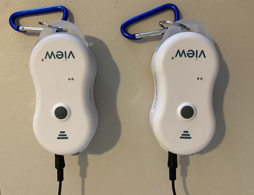
Installation Overview of View Smart Windows and Building Systems

                •   Sky Sensor
                •   Network connection cables

                •   Cell modem

     7.    All building penetrations, coring, raceways and sleeves necessary to accommodate View control cables. This work should be
           coordinated with glazing contractor and GC in accordance with local building codes.

     8. If IGU cable needs to be extended, Low-Voltage or Electrical contractor shall test and label all IGUs using GTT (glazier test tool), see
           GTT guide for labeling protocol.

     9. Labeling all trunk lines, power insert lines and IGU cables per View interconnect drawing.

     10. Perform all Functional Hardware Testing prior to deployment of View FSE (Field Service Engineer).

     11. Provide field support as needed during commissioning phase including, repairing items identified by the View FSE during
           commissioning phase. Any billable hours for troubleshooting should be coordinated with the General Contractor (GC).

     12. Keep track of all cable and equipment changes including lengths, locations and cable pathways. Provide accurate redline drawings to
           View Project Manager at completion of project.

     13. Electrician to provide stable power prior to functional hardware testing and commissioning.

     14. All network cabling and connections between View equipment and customer network. If distance between View control panels exceeds
           100-meters, fiber is required (i.e. control panels and sky sensor).

     15. Some Union projects require the Low-Voltage contractor to install the IGU cables in the glazing system, check with the View project
           manager prior to bidding.

     16. Do NOT field splice IGU cables or Smart Window Connectors.

Rev 01 | Jul 2021                                                      © 2021 View, Inc. All rights reserved.                                      5
Installation Overview of View Smart Windows and Building Systems
Scope of Work: Division Specifications
• Division 8: Dynamic Glazing
• Division 25, 26, 27: Controls for Smart Windows
Low Voltage Electrician
Control Panel
• Electrical Room
• 30A, 208V, 3 Phase Power
Splitter Trunk Cable
• Passive • Plenum Rated
• Low Voltage • Low Voltage
Drop Cable
• Plenum Rated Network Window Controller
• Low Voltage • Compact
• 1 per window
IGU Cable
• Up to 100’
• IP67 rated
IGU Cable
• Up to 100’
Smart Window Connector • IP67 rated
• 1.5” long +/-
• 3” from corner
• Longest side
Glazier (view from inside)
Rev 01 | Jul 2021 © 2021 View, Inc. All rights reserved. 6Installation Overview of View Smart Windows and Building Systems
Basic components for Glaziers
06 IGU Cable 06 IGU Cable
07 Smart 07 Smart
Window Window
Connector Connector
IGU IGU
Glazier Test Tool
(provided by View)
Rev 01 | Jul 2021 © 2021 View, Inc. All rights reserved. 7Installation Overview of View Smart Windows and Building Systems
Glazier Resources
Click here for training resources
https://view.com/training/glaziers
Rev 01 | Jul 2021 © 2021 View, Inc. All rights reserved. 8Installation Overview of View Smart Windows and Building Systems
Glazing Installation Labor Estimate Example
Below is a table showing an example IGU quantity for a 10,000 SF (glass area) building. Also shown are the expected additional installation labor
minutes per IGU and extended total labor hours accounting for the total number of IGUs. This additional installation time is related to the glazier
preparing the IGU frames by drilling holes, deburring hole edges, inserting silicone grommets, and sealing penetrations with silicone as needed to
route IGU cable per View interconnect drawings. Glazier is also responsible for labeling IGU cables per View interconnect drawing. In this exam-
ple, we are using $100.00/hour for the labor rate. We suggest using local market labor rates for this project.
For this example, the IGU and Smart Window Connector are shown in the chart below. The IGU Smart Window Connector will be connected to
the IGU cable by the glazing contractor and needs to be made accessible for the LV Electrician.
LABOR MINUTES PER ESTIMATED TOTAL
DEVICE/ITEM QTY LABOR RATE TOTAL
DEVICE LABOR HOURS
IGU 500 45 375 $100.00 $37,500.00
Rev 01 | Jul 2021 © 2021 View, Inc. All rights reserved. 9Installation Overview of View Smart Windows and Building Systems
View Integration Drawings (example):
IGU CABLE CONNECTION TO IGU ®
SMART WINDOW CONNECTOR
(SWC) IN GLASS POCKET
7/16" DIA. HOLES FOR IGU CABLES
AT ALL VERTICALS. REQ. (1) PER IGU
CABLE. FILE ALL EDGES SMOOTH. VIEW, INC.®
195 SOUTH MILPITAS BLVD.
MILPITAS, CA 95035
v. 408/263.9200
1
--
www.viewglass.com
7/16" DIA. HOLE FOR IGU CABLE TO
SMART WINDOW CONNECTOR (SWC) .
FILE ALL EDGES SMOOTH.
FILL WITH SILICONE SEALANT.
DETAIL 1
HEAD
WRAP ZIP TIE AROUND END OF SMART
WINDOW CONNECTOR (SWC) CONNECTOR
TO RETAIN SMART WINDOW CONNECTOR
(SWC) ACCESSIBLE IN GLASS POCKET FOR IGU CABLE CONNECTION TO
SERVICE. SMART WINDOW CONNECTOR
(SWC) IN 7/16" HOLE. LAY
IGU CABLE CONNECTION TO SMART
REMAINDER OF SMART WINDOW
WINDOW CONNECTOR (SWC) IN 7/16"
CONNECTOR (SWC) IN GLASS
HOLE. LAY REMAINDER OF SMART
POCKET.
WINDOW CONNECTOR (SWC) IN GLASS
POCKET.
2
--
7/16" DIA. HOLE FOR IGU
7/16" DIA. HOLES FOR IGU CABLES CABLE TO SMART WINDOW
AT ALL VERTICALS. REQ. (1) PER IGU CONNECTOR (SWC) . FILE 5 4
CABLE. FILE ALL EDGES SMOOTH. ALL EDGES SMOOTH. FILL -- --
WITH SILICONE SEALANT.
7/16" DIA. HOLE FOR IGU CABLE TO SMART WRAP ZIP TIE AROUND END OF SMART WINDOW CONNECTOR
WINDOW CONNECTOR (SWC) . FILE ALL EDGES (SWC) CONNECTOR TO RETAIN SMART WINDOW CONNECTOR
SMOOTH. FILL WITH SILICONE SEALANT. (SWC) ACCESSIBLE IN GLASS POCKET FOR SERVICE.
DETAIL 2 DETAIL 4
HORIZONTAL MULLION, SILICONE GLAZED VERTICAL MULLION, SILICONE GLAZED
7/16" DIA. HOLE FOR IGU
CABLE TO SMART WINDOW
CONNECTOR (SWC) . FILE
3
--
ALL EDGES SMOOTH. FILL
WITH SILICONE SEALANT.
IGU CABLE CONNECTION TO IGU
PLOT DATE: March 26, 2019
SMART WINDOW CONNECTOR
(SWC) IN GLASS POCKET
DETAIL 3 DETAIL 5 TYPICAL ELEVATION
SILL LEFT JAMB SCALE: NONE
INSTALLATION DETAILS: CURTAINWALL - FOR ARCADIA Ti BEAM 3 SERIES, SSG VIEW INC. CONFIDENTIAL : THIS DOCUMENT AND
1
THE INFORMATION CONTAINED IN IT ARE CONFIDENTIAL,
AND CANNOT BE COPIED OR DISCLOSED IN WHOLE OR IN
SCALE: NONE PART WITHOUT THE EXPRESS WRITTEN CONSENT OF
VIEW, INC. ®
Rev 01 | Jul 2021 © 2021 View, Inc. All rights reserved. 10Installation Overview of View Smart Windows and Building Systems
Low Voltage Electrician Resources
Click here for training resources
https://view.com/training/lve-view-net
Rev 01 | Jul 2021 © 2021 View, Inc. All rights reserved. 11Installation Overview of View Smart Windows and Building Systems
View Net Controls Overview (Base Package)
08 Sky Sensor
12 Pull Box
11 Cell Modem
Assembly
09
Fiber Optic
Connection
02 02 02
03 03 03
Trunk Cable Trunk Cable Trunk Cable
Network Uplink 10
Splitter Splitter Splitter
TRUNK OUT
TRUNK OUT
TRUNK OUT
TRUNK IN
TRUNK IN
TRUNK IN
DROP
DROP
DROP
Input Power
208V, 3 Phase, 30A Drop Cable 04 Drop Cable 04 Drop Cable 04
Network Window Controller 05 Network Window Controller 05 Network Window Controller 05
06 IGU Cable 06 IGU Cable 06 IGU Cable
07 Smart 07 Smart 07 Smart
01
Window Window Window
Control Panel Connector Connector Connector
IGU IGU IGU
09
Fiber Optic
Connection
Rev 01 | Jul 2021 © 2021 View, Inc. All rights reserved. 12Installation Overview of View Smart Windows and Building Systems
Basic Control System Components Descriptions
Cabling System 04 Drop Cable 08 Sky Sensor
The View cabling system uses a trunk line/drop line Provides power and data to the window controller. Ties Used to detect external light and infrared temperature
network topology. In this topology, the trunk cable into the trunk cable via the splitter. Short cables come levels. Data from the sensor is transmitted to the control
carries both power and data through the entire length of pre-terminated. Bulk spool cables must be terminated panel for Intelligence. It is typically mounted on the roof
the installation. Drop cables are then tapped off of the manually. Cables require male BNC connectors. Standard top.
trunk cable using splitters at locations where network coax crimp tool required for termination.
window controllers are installed. The network window Specifications for Sky Sensor:
controllers are then connected to individual IGU units Specifications for Drop Cabling: • Connects to View control panel via CAT5 cable.
via an IGU cable. Note: Component data sheets will • Available in lengths 1’, 5’, 6’ or 500’, 1000’ spools • Mounts to rooftop, must be clear of obstructions,
supersede the information found here. • Available in standard and plenum rated cables 360-degree view of the horizon, POE powered.
01 Control Panel 05 Network Window Controller
09 Fiber Optic Connection
Wall-mounted enclosure (72” x 30” x 9”) that contains Facilitates power transmission to each IGU. Connected
the power supplies, floor controller, as well as auxiliary to a drop cable on one end and an IGU cable on For connection of multiple control panels on a site.
connections such as Ethernet and external sensors. At the other end. Must be installed at an accessible,
least one control panel is required for each installation. environmentally controlled location. One network Specifications for Fiber Cables:
Each control panel can support up to 288 window window controller is installed per IGU. Includes one • Single Mode fiber
controllers. Actual limits may vary depending on POE port via an IX connector. • Armored Cable with 96 strands
specific project considerations. For larger or multi-floor • Available in pre-terminated and field terminated
installations, multiple control panels may be required. Specifications for Window Controllers: lengths
Each Control Panel requires a dedicated 30-amp circuit • Input: 48 VDC
(30-amp@208 VAC 3 phase). • IGU Output: Range between + 5 VDC
• Dimensions: 1” x 1.47” x 5.63” 10 Network Uplink
Specifications for Control Panel: • POE Output: 48V, 7W Contractor required to connect to customer network via
• Input: AC 208V + 15% ethernet or fiber (refer to View Interconnect drawing).
• Frequency: 50-60 Hz + 6%
• Output Class: 2 48 VDC
06 IGU Cable
Connects a network window controller to the IGU Smart
Window Connector cable. 11 Cell Modem
02 Trunk Cable Used as a temporary network connection to the View
Provides power and data to the window controller. Specifications for IGU Cabling: Site Ops monitoring system. Requires 110/120VAC 60Hz.
Short cables come pre-terminated. Bulk spool cables • Standard Tinting: Available in lengths from 1’ to 100’
must be terminated manually. Cables require male BNC (meter or fractional meter increments)
connectors. Standard coax crimp tool required for • Fast Tinting: Available in lengths from 1’ to 50’
termination. • Available in standard and plenum rated cables 12 Pull Box
• Max combined length from the WC to the IGU is 100’ Used for storing extra ethernet cable to Sky Sensor.
Specifications for Trunk Cabling:
• Max combined length approx. 1,000’
• Available in lengths 1’, 5’, 6’ or 500’, 1000’ spools 07 IGU Smart Window Connector
• Available in standard and plenum rated cables Each IGU receives power from the control system
through an IGU Smart Window Connector. The Smart
Window Connector is embedded with a digital ID that is
03 Splitters unique to that IGU’s dimensions and specifications.
Used to connect drop cables to the trunk cable. Splitters
come in WYE configuration. Specifications for IGU Smart Window Connector:
• ~15.5” +/- 1.5” length located 3” from corner. Location
changes based on shape and dimensions. See IGU
data sheet for exact location.
• Requires 7/16” hole size
Rev 01 | Jul 2021 © 2021 View, Inc. All rights reserved. 13Installation Overview of View Smart Windows and Building Systems
View Net Controls Overview (IoT-Ready Package)
08 Sky Sensor
12 Pull Box
11 Cell Modem
Assembly
09
Fiber Optic
Connection
02 02 02
03 03 03
Trunk Cable Trunk Cable Trunk Cable
Network Uplink 10
Splitter Splitter Splitter
TRUNK OUT
TRUNK OUT
TRUNK OUT
TRUNK IN
TRUNK IN
TRUNK IN
DROP
DROP
DROP
Input Power
208V, 3 Phase, 30A Drop Cable 04 Drop Cable 04 Drop Cable 04
Network Window Controller 05 Network Adapter 15 Network Window Controller 05
13 PoE Port 13 PoE Port
IGU Cable 06
IGU Cable 06
Smart Window Connector 07
Smart Window Connector 07
14 PoE Cable 14 PoE Cable 14 PoE Cable
01
Control Panel
16
Third Party
Devices
09
Fiber Optic
Connection View Sense IGU View Sense IGU
Rev 01 | Jul 2021 © 2021 View, Inc. All rights reserved. 14Installation Overview of View Smart Windows and Building Systems
Basic Control System Components Descriptions
Cabling System 05 Network Window Controller 09 Fiber Optic Connection
The View cabling system uses a trunk line/drop line network Facilitates power transmission to each IGU. Connected to a For connection of multiple control panels on a site.
topology. In this topology, the trunk cable carries both power drop cable on one end and an IGU cable on the other end.
and data through the entire length of the installation. Drop cables Must be installed at an accessible, environmentally controlled Specifications for Fiber Cables:
are then tapped off of the trunk cable using splitters at locations location. One network window controller is installed per IGU. • Single Mode fiber
where network window controllers are installed. The network Includes one POE port via an IX connector. • Armored Cable with 96 strands
window controllers are then connected to individual IGU units via
• Available in pre-terminated, field terminated lengths
an IGU cable. Note: Component data sheets will supersede the Specifications for Window Controllers:
information found here. • Input: 48 VDC 10 Network Uplink
• IGU Output: Range between + 5 VDC
01 Control Panel Contractor required to connect to customer network via ethernet
• Dimensions: 1” x 1.47” x 5.63”
Wall-mounted enclosure (72” x 30” x 9”) that contains the power or fiber (refer to View Interconnect drawing).
• POE Output: 48V, 7W
supplies, floor controller, as well as auxiliary connections such
as Ethernet and external sensors. At least one control panel is 06 IGU Cable 11 Cell Modem
required for each installation. Each control panel can support
Connects a network window controller to the IGU Smart Used as a temporary network connection to the View Site Ops
up to 288 window controllers. Actual limits may vary depending
Window Connector cable. monitoring system. Requires 110/120VAC 60Hz.
on specific project considerations. For larger or multi-floor
installations, multiple control panels may be required. Each
Control Panel requires a dedicated 30-amp circuit (30-amp@208
Specifications for IGU Cabling: 12 Pull Box
• Standard Tinting: Available in lengths from 1’ to 100’ (meter Used for storing extra ethernet cable to Sky Sensor.
VAC 3 phase).
or fractional meter increments)
• Fast Tinting: Available in lengths from 1’ to 50’
Specifications for Control Panel:
• Available in standard and plenum rated cables 13 PoE Port
• Input: AC 208V + 15%
• Max combined length from the WC to the IGU is 100’ Industrialized IX power over ethernet port that conforms to PoE
• Frequency: 50-60 Hz + 6%
standard 802.3af. Capable to supply data and power connectivity
• Output Class: 2 48 VDC
to any device within 100m using IX category 5e or better cable.
07 IGU Smart Window Connector
02 Trunk Cable
Provides power and data to the window controller. Short cables Each IGU receives power from the control system through an
14 PoE Cable
come pre-terminated. Bulk spool cables must be terminated IGU Smart Window Connector. The Smart Window Connector
is embedded with a digital ID that is unique to that IGU’s IX Category 6 28 AWG cable for Power over Ethernet
manually. Cables require male BNC connectors. Standard coax
dimensions and specifications. connectivity to the View Network Window Controller. Available in
crimp tool required for termination.
pre-terminated lengths from 1M to 10M.
Specifications for Trunk Cabling: Specifications for IGU Smart Window Connector:
• Max combined length approx. 1,000’ • ~15.5” +/- 1.5” length located 3” from corner. Location 15 Network Adapter
• Available in lengths 1’, 5’, 6’ or 500’, 1000’ spools changes based on shape and dimensions. See IGU data
Provides ethernet connectivity to devices connected to IX Port.
• Available in standard and plenum rated cables sheet for exact location.
• Requires 7/16” hole size
Specifications for Network Adapters:
03 Splitters • Input: 48 VDC
Used to connect drop cables to the trunk cable. Splitters come in • IGU Output: Range between + 5 VDC
08 Sky Sensor
WYE configuration. • Dimensions: 1” x 1.47” x 5.63”
Used to detect external light and infrared temperature levels.
Data from the sensor is transmitted to the control panel for • POE Output: 48V, 15W
04 Drop Cable
Intelligence. Typically mounted on the roof top.
Provides power and data to the window controller. Ties into the
trunk cable via the splitter. Short cables come pre-terminated. Bulk 16 Third Party Devices
Specifications for Sky Sensor:
spool cables must be terminated manually. Cables require male
• Connects to View control panel via CAT5 cable. All third party devices must be compliant with PoE 802.3af and
BNC connectors. Standard coax crimp tool required for termination.
• Mounts to rooftop, must be clear of obstructions, use less than 7W of peak power. Device power consumption
360-degree view of the horizon, POE powered. must be confirmed with View prior to installation to ensure the
Specifications for Drop Cabling:
devices does not exceed the coaxial cable power limit.
• Available in lengths 1’, 5’, 6’ or 500’, 1000’ spools
• Available in standard and plenum rated cables
Rev 01 | Jul 2021 © 2021 View, Inc. All rights reserved. 15Installation Overview of View Smart Windows and Building Systems Interconnect Drawings View provides comprehensive interconnect drawings for each project. Sample drawings available upon request. Please contact LVEBootcamp@view.com for more information. Data Sheets Typically used Data Sheets are available on the View website. Rev 01 | Jul 2021 © 2021 View, Inc. All rights reserved. 16
Installation Overview of View Smart Windows and Building Systems

Glass Implementation Process

                                         Provide                                                                                    Install View
   GC Electrician
   LV Contractor

                                        feedback                                                                                    controls and
                                       for Controls                                                                                  complete
                                      System design                                                                                  Functional
                                                                                                                                     Hardware
                                                                                                                                      Testing

                                                              Provide
                                                             feedback
                                                            for Controls
                    Project Kickoff                        System design
                       Meeting
                        (scope,
                      schedule,
                      planning)
                                                                                      Finalize IGU
   Glazier

                                      Provide facade                                   order with
                                        shop detail                                                                 Install IGUs,
                                                                                     signed Order                    functional
                                                                                     Acknowledge-                      check
                                                                                         ment

                                                                                                                                                    Commission
                                         Provide              Provide                 Consolidate                   Manufacture     Ship Controls    system and
   View

                                         product              product                  input and                    and ship IGU       System          provide
                                       information          information              produce Final                    cables to                       turnover
                                        and design           and design              Interconnect                      Glazier                      package and
                                        guidelines           guidelines                 Drawing                                                       operation

Rev 01 | Jul 2021                                                          © 2021 View, Inc. All rights reserved.                                                 17
Installation Overview of View Smart Windows and Building Systems
Glazier Test Tool (GTT)
The View Glazier Test Tool (GTT) is a portable convenient way to test View IGU,
IGU pigtail and cable operation. In a 30-60 second test, the GTT will indicate
whether the windows, pigtails, and cables are connected and operating properly.
This device should be used on all View installations.
This device is designed for use by Glaziers, Low-Voltage Electricians and View
FSE’s who install and test View Smart Windows.
What’s Included:
Glazier Test Tool Silicon Cover Pigtail Caps (x10) DC Charger
010-101781 020-101673 370-101509 750-101502
WSW
Grounding Connector Alligator Clip Cable
370-101516 380-101558
Rev 01 | Jul 2021 © 2021 View, Inc. All rights reserved. 18You can also read