1987-89 Ford Mustang Classic Update Series 510547

Page created by Chris Barrett
 
CONTINUE READING
1987-89 Ford Mustang Classic Update Series 510547
1987-89 Ford Mustang
                                                          Classic Update Series
         www.americanautowire.com          856-933-0801
                                                          510547       © COPYRIGHT 2004 American Autowire / Factory-Fit
                                                                              Used with express permission of
                                                                               American Autowire / Factory-Fit

          DESIGN ASSISTANCE PROVIDED BY:
Page 1                                                                 92970659           Rev 0.0        9/22/2014
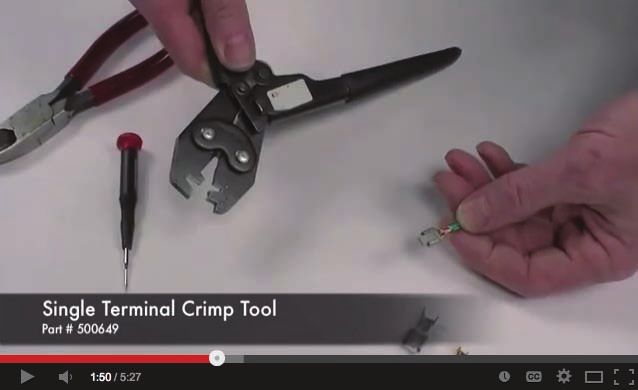
1987-89 Ford Mustang Classic Update Series 510547
START HERE !
                                                                                                The terminals that we supply in our kits, utilize what is known as an F crimp. The F crimp,
                                                                                                in a cross section, will look like the illustration below, when done correctly.
                                                                                                                                                                   wire core
         PLEASE READ THIS BEFORE STARTING INSTALLATION !
   This wiring kit is designed for ease of installation. Please read the guidelines below,
   BEFORE STARTING your installation, to guarantee a successful job. Use an appropri-                             end view of                      proper crimp
   ate crimping tool, which folds the wings of the open barrell terminals down into the                       un-crimped terminal                   of terminal
   wire, as shown on this page. ALL TERMINALS THAT YOU INSTALL SHOULD BE
   PROPERLY SOLDERED. Our factory crimped terminations are installed by GM                           We carry the following crimping hand tools, to help with your terminal crimping.
   approved five ton presses, and soldering these terminations is not necessary.                     These hand tools are available, for purchase or rental.

                                                                                                       AAW p/n 500649                                        AAW p/n 500523
                                                                                                    OEM small terminal crimping                          OEM large terminal crimping
                                                                                                       tool (18-14 gauge)                                    tool (12-8 gauge)

   AAW offers a great terminal crimping video entitled “Proper Crimping Video”. It can
   be viewed by visiting YouTube.

   Type the following address into your web browser, to go directly to the video:
   www.youtube.com/watch?v=8u_EkMsioMy

   Youtube Channel:                                                                                           We carry many accessories for your 1987-89 Ford Mustang.
   www.youtube.com/user/WiringHarness
                                                                                                           p/n 500479                                             p/n 500802
                                                                                                                                                        GM “SI” series to Ford “3G” internal
                                                                                                          Universal Relay Kit
                                                                                                                                                               regulated alternator

                                                                                             STEP 1: DISCONNECT YOUR BATTERY:
                                                                                             Disconnect the battery, before installing the wiring kit, to prevent any accidental shorting
                                                                                             caused by loose bare wire ends.
                                                                                                                                                          1987-89 Ford Mustang
                                                     If you have any questions concerning this or any of our products,                                    Classic Update Series
Page 2     www.americanautowire.com   856-933-0801
                                                     please feel free to call us at 1-856-933-0801.                                                       510547 92970659 Rev 0.0 9/22/2014
1987-89 Ford Mustang Classic Update Series 510547
STEP 2: START INSTALLING KIT:                                                                                 Connector terminal removal instructions:
 This kit is broken down into individual sections, that are identified by a letter printed on the enclosed
 sheets, visible through each bag. The order of installation and the pages with their installation           You will need to remove the terminals, from
 instructions, are shown below:                                                                              the connectors that are to be salvaged from
                                                                                                             your original harnesses. Looking into the
                                                                                                             openings in the mating end of the connector,
 Table of Contents:                                                                                          you will need to push the small latches
                                                                                                             inside, towards the outside of the connector
Bags: Pages: Sections:                                                                                       body, while gently pulling the wire and                                        Latch
                                                                                                             terminal, from the other end.
  G        4 - 14       Dash Harness - This is the main harness in the kit and contains:                     Be careful not to break the latches.
                        - Starter solenoid connections.          - Door jamb switches.
                        - Wiper motor connections                - Wiper module and switch connections
                        - Brake light switch connection.         - Defrost module and switch connections.
                                                                                                                                                                             Push in latches here, to
                        - Neutral safety switch connection.      - Headlight and fog light connections.
                                                                                                                                                            SC               remove retaining strip.

  H       15, 16        Gauge Cluster Harness - This Harness contains:                                       The white Defrost Module connector
                        - Gauge connections for aftermarket gauges.                                          to the right, needs to have the black
                                                                                                             retaining strip removed, prior to
                                                                                                             pushing the latches, to release
  M       17, 18 Rear Body Harness - This Harness contains:
                                                                                                             the terminals. This retaining strip
                        - Tail light, turn signal, reverse light, and running light connections.
                                                                                                             will be replaced, after the new
                        - Hatch connections; third brake light, license plate lights, and rear defroster
                                                                                                             terminals are installed. If the strip
                          connections.
                                                                                                             should break, during removal, the
                        - Fuel pump connections.
                                                                                                             connector will still work without it.
  L      19 - 22 Front Light Harness - This Harness contains:
                        - Headlight, turn signal, running light connections.
                        - Fog lamp wiring.                                                                   The two Wiper Motor connectors, have a retaining clip on the wire side, that must be
                        - Windshield washer connection.                                                      removed, prior to pushing the latches to release the terminals. These retaining clips
                        - Electric fan relay trigger.                                                        will be replaced, after the new terminals are installed. If the clips should break,
                        - Brake fluid level wiring.                                                          during removal, the connectors will still work without them.

   J     23 - 25        Engine Harness - This Harness contains:                                              retaining                                   retaining
                        - Temperature, oil pressure, tachometer wiring.                                         clip                                        clip
                        - Ignition system / ECU power.
                        - A/C compressor connections.
                        - Alternator connections.                                                                     SJ                                          SL
                                                                       1987-89 Ford Mustang
                                                                       Classic Update Series
                                                                                                                   The terminals are not shown in these views, for clarity.
Page 3        www.americanautowire.com   856-933-0801                  510547                                                                                                92970659   Rev 0.0   9/22/2014
1987-89 Ford Mustang Classic Update Series 510547
Dash/Main Harness installation instructions:
   Shown below, are the connectors and grommets you will need to salvage/remove from your original Dash harness, that will be re-used (along
   with the supplied parts, on the following page) to complete your Dash/Main harness connections. They are itemized and referred to on this
   page, just as they are on the following pages of this Dash/Main instruction set (also see page 17, for parts salvaged from your original Rear
   Body harness). Terminal removal instructions, are on page 3. The original “donor” harnesses, for these salvaged parts, are in years 1987-93.
    Salvaged AC Mode selector
         switch connector          Salvaged Defrost Module (Black)    Salvaged Defrost Module (White)         Salvaged Defrost switch          Salvaged Fog Lamp switch

                                                                                                           SD                                SE
SA                               SB                                  SC

                                                                                                        Salvaged Wiper Module
         Salvaged Illumination                                                       5.00                 (cut existing wires,
           Lamp connector             Salvaged Interior Dimmer                                             to length shown)                 Salvaged Wiper Motor (Black)

    SF
                                 SG                                                                                                       SJ

                                                                                               SH
                                                                                                                            Salvaged
                                                                                                                                ECU
                                                                          Salvaged Main
                                                                                                                              firewall
         Salvaged Blower Motor      Salvaged Wiper Motor (Gray)               firewall
                                                                                                                            grommet
                                                                             grommet
                                                                                                                          (if required)

 SK
                                 SL                                  SM                                 SN
                                                                                                                                                  www.americanautowire.com   856-933-0801

                                                                                                                                          1987-89 Ford Mustang
                                                                                                                                          Classic Update Series
Page 4                                                                                                                                    510547 92970659 Rev 0.0 9/22/2014
Dash/Main Harness installation instructions:
      Shown below, are the supplied misc. terminals, plastic connector bodies, hardware, and bracket, that will be used (along with the salvaged
      parts that were removed from your original Dash harness, from the previous page) to complete your Dash/Main harness connections. They
      are itemized and referred to on this page, just as they are on the following pages of this Dash/Main instruction set.
                                                                  (single male
                       (Pack-con 2-way                L                                               PLEASE READ THIS HELPFUL INSTALLATION TIP,
             B A

  A                    male conn, 1 pc.)
                                                                  terminal,3 pcs.)
                                                                                                             BEFORE GOING ANY FURTHER!
                        (male flat Pack-con           M           (sleeve, 6 pcs.)
  B                     terminal, 11 pcs.)                                                       Prior to installing the Dash/Main harness in your dashboard,
                                                                                                 plug all of the fuses and circuit breakers (see detailed picture
                                                                                                  below), Horn Relay, Hazard Flasher and Turn Flasher (see
               (Pack-con 9-way male
  C            conn, 1 pc.)
                                                                                                            detailed picture below), into this harness.

                                                                                                                                            30     1   2    30
                      (56 series single female                                                         Trim leads of both                        Bussmann
  D                   terminal, 7 pcs.)               N                                                                                     15     3   4    30
                                                                                                         circuit breakers,
                                                                                                                                                   5
                                                                                                       where shown, prior                              6    20

  E        (10-32 nut, 1 pc.)                                                                          to installing in fuse                20     7   8    30

                                                                                                                box.                        15     9   10   10

  F          (10-32 screw, 5 pcs.)                                                                                                          15     11 12    15

                                                                                                                                                   13 14
  G
                                                                                                                                            20              20
                   (large box terminal, 5 pcs.)
                                                                                                                                                   15 16    30

  H           (small box terminal, 3 pcs.)                (Fuse box mounting
                                                             bracket, 1 pc.)                                         Horn Relay
                                                                                                       Hazard                         Fuse, Circuit Breaker
                      (56 series 2-way                                                   Turn Flash     Flash
                                                                                                                                     installation orientation.
  J                   female conn, 2 pcs.)                          (56 series 3-way
                                                      P             male conn, 2 pcs.)

                     (single female
  K                  terminal, 3 pcs.)                           (56 series 3-way
                                                      R          female conn, 1 pc.)

                                                                                                                                      1987-89 Ford Mustang
                                                                 (56 series single
                                                      T          male terminal, 3 pc.)                                                Classic Update Series
Page 5      www.americanautowire.com   856-933-0801                                                                                   510547 92970659 Rev 0.0 9/22/2014
Dash/Main Harness installation instructions:
                                                                                        Instrument
                                                                                         Rheostat
 It is recommended that the connector terminations
  and harness installations, on the following pages,
    are performed in the order they are presented.                                                                                                 either brown wire can
                                                                                                                                                   be plugged into either
                                                                                                                                                   of the center cavities
    The connectors on this page, should have their                            SG
     wires installed, on a bench or work area, prior
      to installing the harness, in the dashboard.
                                                                                                                                                                       Rear Defrost

            Wiper Motor 1
                                   Wiper Motor 2                                                                   SF                           SA

                                                                                                                                                               SD
                                                                                                     Blower
   SJ                                              SL        Fog Lamp
                                                                                                     Motor              A/C Panel
                                                                                                                                     A/C Mode
                                                                                                                                      Switch
                                                              Switch                                                    Illuminate

                                                        SE                                                    SK
                                                                        either terminal can
                                                                          be plugged into
                                                                            either cavity

                                                                                                                                            1987-89 Ford Mustang
 www.americanautowire.com   856-933-0801                                                                                                    Classic Update Series
Page 6                                                                                                                                      510547    92970659 Rev 0.0 9/22/2014
Dash/Main Harness installation instructions:
     The terminals and connectors on this page,
    should be installed on a bench or work area,
                                                                   ‘87-’89                                                            G
                                                                                                                                                 Salvaged Defrost
                                                                                                                                                  Module (Black)
   prior to installing the harness in the dashboard.

                                                                                                                                                                                        SB

         WARNING:
                                                                                         Rear Defroster Module Extension
                                                                                                                                      G
         Do not remove the Power Windows/
         Locks/Mirrors harness, that runs along
         the top of the firewall, behind the dash
                                                        ‘90-’93
                                                                                                                                           Salvaged Defrost
         board, if you plan on using Power                                                                                     H            Module (White)
         Windows/Locks/Mirrors.

                                                                                                                                                                              SC

                                                                                 Rear Defroster Module Extension                G

                                             C      B                                                         Salvaged Wiper Module
                                                         yellow/red
            black/pink     brown/white                                 black/pink
                                                           white
                white      (2) black/white

                                                                                                                                      SH
                                                                          red
                                                                                                                                              www.americanautowire.com   856-933-0801
            yellow/red                                     black
                                                                        orange
                green      orange
                                                         brown/white
                  red      black                                       (2) black/white
                                                                                                                                           1987-89 Ford Mustang
                                                           green
                                                                                                                                           Classic Update Series
                                                    B
Page 7                                                                                                                                     510547    92970659 Rev 0.0 9/22/2014
Dash/Main Harness installation instructions:                                             Rear of Dashboard                                  Horn Relay

           Engine                                                                                          Turn
                                                                                                          Flasher
                                                                                                                                                                                                Wiper
                                                                                                                                                                                                Module
                                                                                                                                                                                                                Underdash
                                                                                                                                                                                                                 Courtesy

                                                                                                                                                                                                D C B A

                                                                                                                                         Rear
                                                                                                                                        Defrost
                                                                                                                                        Module
                                                                                                                              Hazard
                                                                                                                              Flasher

                                                                                                    Windows     Door Locks                                                               A B
                                                                                                                                                              Fuse Box
                                                                                                      and          and
                                                                                                                                                             (90-93 mount)
                                                                                                     Mirrors     Releases
                                                                        SK            Ground                                                                                                   NSS
                                                                                                             Ground
                                                                                                                                  Brake
                                                                                                                                  Switch
                      Dome & Map                                   Blower
                                                                                                                                                                 F
                                                                                                                                                                     E
                                                                                                                                                                         D
                         Light                                     Motor
                                                                                                                                                                             C
                                                                                                                                                                                 B
         Underdash
                                                                                                                                                                                     A

          Courtesy                                  Blower                                                                     Front
                                                    Resistor   Remove the dashboard from the car and                           Light
                                                               lay your new dashboard harness on the                                                                         Rear
                                                                  back of the dashboard, as shown.                                                                           Body

                                                               Prior to installing the Dash Harness in the                              Wiper                                                                        Door
                                                                  back of the dashboard, see the next                                   Motor 1                                                                      Jamb
Door
Jamb                                                            page, for those connectors and wires, to                                   SL
                     www.americanautowire.com   856-933-0801
                                                               be routed out the front of the dashboard.                Wiper
                                                                                                                        Motor 2
                 1987-89 Ford Mustang                           Connect the Ground ring terminals, to                        SJ
                 Classic Update Series                                a good chassis ground.                                                        Engine

Page 8           510547                                                                                 Main Power Feed                                                                    92970659       Rev 0.0   9/22/2014
Dash/Main Harness installation instructions:                                                                Front of Dashboard (instrument panel removed)

                                                                           Instrument         Instrument
                                                                            Cluster 2          Cluster 1
                                                                           A
                                                                       B
                                                                   C
                                                               D

                                                       Instrument
                                                        Rheostat
                                                                                      SG                                             Horn
                                                                                                                                    Switch

                                                                                                                       A
                                                                                                                           B

                                                                                                                     High
                                                                                                                    Beam
                                                                Turn
         Headlight                                             Signal
                                                                                                                    switch                                                                      SF
          Switch
                                                                                                                                                                                                       A/C Panel
                                                                                                                                                           K J H                                       Illuminate

         Fog Lamp                                                                                                                                 Cigar
          Switch             SE                                                                            Wiper
                                                                                                                                                 Lighter                                    A/C Mode
                                                                                                                                                                                             Switch
                                                                           Ignition                        Switch
                                                                                                                                                SD         VSS                           SA
                                                                                                                           Hazard      Rear
                                                                                                                                      Defrost                              Blower
                                                                                                                                                                   Radio
                                                                                                                                                                           Switch

                                                                                            While installing the Dash Harness in the back
                                                                                           of the dashboard, route these connectors and
                                                                                           wires out the front of the dashboard, as shown.                                   1987-89 Ford Mustang
                                                                                                                                                                             Classic Update Series
Page 9           www.americanautowire.com   856-933-0801                                                                                                                     510547    92970659 Rev 0.0 9/22/2014
Dash/Main Harness installation instructions:
 1987-89 Fuse Box installation:                                                                                                  1990-93 Fuse Box installation:
                                                    Trim back dashboard, just enough
                                                          to avoid screw heads.

                                                                                            Trim back dashboard,

                  F                  F                                            F          just enough to avoid
                                                                                               Fuse Box. Leave
                                                                                           enough material, under
                                                                                                the screw head.

                                                                  20
                                                          15

                                                                          30
                                                     10
                                               30
                                          20
                                 30
                         30

                                                                                                                                                                                                                dashboard
                          Bussmann

                                                                          15 16
                                                                  13 14
                                                          11 12
                                                     10
                                               8
                                          6
                                 4
                         2

                                                    9
                                               7
                                         5
                                3
                         1

                                                           15

                                                                   20
                                                     15
                                               20
                                 15
                         30

                                                                                                                                 Mount Fuse Box and mounting bracket “N”,
                                                                                                                                  to metal rail in back of dashboard, where
                                                                                                                                   original Fuse Box was mounted, using
                                      F                                   F                                                              original mounting hardware
                                                                                                 dashboard
                                                                                                                                     (remainder of Dash Harness, is not
                                                                                                                                             shown in this view).

                                                                     N

     Front of dashboard, with Fuse Box access panel removed.
                                                                                                                                                                              End view section of dashboard,
                                                                                                    dashboard                                                                   viewed from driver’s side.

                                                                                                                                                    N

                                                                                                N

                 E
                                                                                                                                                                                   www.americanautowire.com   856-933-0801
                                                                                      Mount Fuse Box and mounting bracket “N”,
                                                                                       to back of dashboard, with bent end of
                                                                                        bracket, angled away from dashboard                                                    1987-89 Ford Mustang
                                                                                         (remainder of Dash Harness, is not
                                                                                                 shown in this view).                                                          Classic Update Series
                 Looking up, at bottom edge of dashboard,
Page 10            with Fuse Box access panel removed.                                                                                                                         510547    92970659 Rev 0.0 9/22/2014
Dash/Main Harness installation instructions:                                                                                       Plug these connectors into their mating connectors,
                                                                                                          Original wires               found on the blower plenum, under the dash.
Plug these connectors into their mating connectors,                                                        from Horn
 found at the steering column. See the note at the                                              B
    Wiper Switch connector, for ‘90-’93 models.
  Cut the original terminals, from the original Horn                                                B

                                                                                            A
                                                                                                B
      wires and terminate the wires as shown.
                                                                                                A
                                                                                                                                                                                           SK

                                                                        A
                                                                                  Horn

                                                                          B
                                                                                 Switch
                                                                                                          Plug these connectors into their
                                                                                                         respective switches, found under
                                                                                                        the dashboard, above the pedals.
                                                                                                                                                                                          Blower
                                                                                                                                                                                          Motor
                                                                               High-Beam
    Turn                                                                         switch
   Signal

                                                                                                                                                                   Blower
                                                                                                                                                                   Resistor

                                                                                 ‘87-’89                                          A B

                                                                                                                                             NSS
                                                      Wiper                                                                             (Dash Harness)
            Ignition                                  Switch
                                                                            WARNING:                      Brake                                      Optional for auto
                                                               The Wiper Switch connector, comes          Switch                                      transmissions.
                                                               wired for ‘87-’89 models, as shown
                                                               above. For ‘90-’93 models, remove                                                                                     Original wires
                                                                the orange, white and black/white                                                                                    from Neutral
                                                               wires and re-insert them, as shown                                                                                    Safety Switch
                                                                               below.
                                                                                                                Neutral Safety
                                                                                      ‘90-’93
                                                                                                               Switch Extension

                                                                                                                                                                 1987-89 Ford Mustang
                                                                                                                                                                 Classic Update Series
Page 11
            www.americanautowire.com   856-933-0801                                                                                                              510547    92970659 Rev 0.0 9/22/2014
Dash/Main Harness installation instructions:                                                                                    Route the Engine, Front Light, Wiper, Ground and the
                                                                                                                                 red Main Power Feed wires, through the driver side of
                                                       Plug the wiper connectors into                                            the firewall, using the large circular grommet (SM)
                                                       the wiper motor.                                    SM
                                                                                                                                 salvaged from the original dash harness. Make sure
                                                                                                Wiper                            the Ground is connected to a good chassis ground.
                                                                                                Motor 1

                                                                Wiper                            SL
                                                                Motor 2
                                                                                                                                 The Engine, Front Light, and red Main Power Feed can
                                                                  SJ                                                             be routed in the engine compartment or in the inner
                                                                                                                                 fender to hide the wires.

                                                                                                                        Engine
                                                                                                                Front
                                                                 Ground
                                                                                                                Light                    Starter solenoid
                                                                                                  Main Power
                                                                                                     Feed

                                                                            LITTLEFUSE

                                                                                         MEGA
                                                                                         175A

                                                    Mount the Mega Fuse (500689) included with this kit in a location close to the starter
                                                    solenoid. Route red main power feed to the Mega Fuse. Cut to length and install ring
                                                    terminal per the instructions included with the Mega Fuse. Use cut off portion of red
                                                    power feed wire, to connect the Mega Fuse to the battery side of the starter solenoid,
                                                    using the ring terminals supplied with the Mega Fuse kit.
                                                                                                                                                             1987-89 Ford Mustang
                                                                                                                                                             Classic Update Series
Page 12
          www.americanautowire.com   856-933-0801                                                                                                            510547    92970659 Rev 0.0 9/22/2014
Dash/Main Harness installation instructions:

 Use radio manufacturer’s instructions
 to connect your radio.
                                                                   Radio
 The functions of the wire’s provided
 in the dash harness are:
                                                                                                                                         K J H
                                                                                                                                                         Cigar
    Gray   - Dash Lights                                                                                                                                Lighter
    Tan    - 12v battery feed for
               Clock or memory                                               back-up light                                                       VSS
    Yellow - 12v accessory feed                                                 switch                                                                                                                     SF                       SA
               for main radio power
    Black - Ground                                                            see page 18
                                                                                                                                                                                        Blower                  A/C Panel                         A/C Mode
                                                                                                                                                                                        Switch                  Illuminate                         Switch
                                                                                                                                        H J K
                                          Aftermarket VSS                                                                                                          P
                                           connections:
                                                                                                                                                                                                 LO
                                                                                                     VSS Signal and VSS                                                                                                             NORM
                                                                                                                                                                                                                                           VENT   OFF   FLOOR
                                                                                                                                                                                                                                                           MIX
                                                                                                                                                                                                                                     A/C
                                                                                                     Ground wires, must                                                                               HI                            MAX
             VEHICLE SPEED SENSOR                                                                                                                                                                                                   A/C

                   (16000 pulse)                                                                     be twisted together,
                                                                                                      their entire length
                                                    gasket
                                                             nut

                                                                                      sensor
                                                                     shaft   o-ring

                                                                                                  VEHICLE SPEED SENSOR
                                                                                                        (8000 pulse)                         T
                                                                                                                            VSS
                                                                                                                                                                        M
                                                                                                Typical 2 wire             Ground        P
                                     VSS                      VSS                              VSS connection

Typical 3 wire Autometer            Ground                   Ground                                                                                                         K
 5291 VSS connection                (black)                  (white)                                                      VSS
                                                                                                                         Signal
                                                 VSS                                             VSS
                                                                                                                                          VSS                                   L
                                                Signal                                          Signal
                                                                                                                   VSS                   Power
                                                (white)                                         (black)
                                                                                                                  Ground                                                                                        www.americanautowire.com    856-933-0801

VSS Signal and VSS                                                                                                                                                                  M
Ground wires, must                                                                                                                  R
be twisted together,                                                                                                                                       cigar lighter                                   1987-89 Ford Mustang
 their entire length
                                        VSS                                                                                         D                    illumination                                      Classic Update Series
                                       Power                                                                                                       parking brake
Page 13                                 (red)                                                                                                                                                              510547    92970659 Rev 0.0 9/22/2014
Dash/Main Harness installation instructions:

                       D              J

                                                                                                                 original wires:
                                                        Windows
                                                                     Door                         D              black/ lt blue = dome
                   D                                                Locks
                         original wires:                  and                                                    lt green/ yellow = map
                                                                     and
                         black/white = power locks       Mirrors
                         pink = power windows
                                                                   Releases                                 D

                                                                                                      J

                              Disconnect the Door Jamb switch                                     Dome & Map
                              disconnect so that the wires do                                        Light
                              not become twisted while
                              threading the Door Jamb switch
          Underdash           in. Reconnect when switch is fully
           Courtesy           installed.

                              Disconnect switch from white
                              connector. Pass white connector
                              through the courtesy switch hole
                              from the inside. Reconnect to
                              the switch then thread switch in                       Underdash
                              from the outside.                                       Courtesy
 Door
 Jamb

                                                                                                 1987-89 Ford Mustang
                                                                                                 Classic Update Series
                                                                              Door
Page 14    www.americanautowire.com   856-933-0801                            Jamb               510547    92970659 Rev 0.0 9/22/2014
Gauge Cluster Harness (aftermarket gauges) installation instructions:
                                                                      TURN SIGNAL AND HI-BEAM LAMP CONNECTIONS

                                                              LEFT TURN IND         HIGH BEAM IND      RIGHT TURN IND

              33                                                  lt blue                 lt green        dk blue
                                                               (LH turn ind)         (hign beam ind)    (RH turn ind)
  25

                                                                                                                           _    +      S     +               +      S             +              S              +
                                                                                                                                                      S

                                                    33                                                                                                                                                        TACH
                                                                                                                               VOLTS       FUEL   SPEEDO   OIL                  TEMP
                                                    25

                                                                   ALTERNATOR     BRAKE WARNING
                                                                   LIGHT          LIGHT

                                                                                                                                                           Below are some general instructions for hooking up an electric speedometer.
                                                                                                                                                           This connector and these instructions will ONLY be used in the event that
                                                                                                                                                           you are utilizing an aftermarket electric speedometer. If your car does NOT
                                                                                                                                                           have an electric speedometer, this connection will NOT be used and should
                                                                                                                                                           not be plugged onto your dash harness. It is best to consult the speedometer
                                                                                                                                                           manufacturer’s instructions if you have any questions.

                                                                                                                                                           Yellow       VSS Ground        Connect to VSS neg. “--” on speedometer.
                                                         D C B A

139                402                                                                                                                                     Purple       VSS Signal        Connect to VSS input on speedometer.
                                                                     139
                   401                                                                                  Speedo power                                       Purple/White VSS Power         Connect to 12V power on speedometer.
                                                                     400
                   400                                                                                  VSS Ground                                         Black/White Speedo Ground Connect to ground on speedometer.

                                                                     401                                                                                   Pink/White   Speedo Power      Connect to 12v power on speedometer.
                                                                                                        VSS Signal                                                                        NOTE: This wire will double onto the same
                                                                     402                                                                                                                  stud as the purple/white VSS power wire
                                                                                                                                                                                          from above.
                                                                                                        VSS Power

                                                                                                                        See page 16.                                             1987-89 Ford Mustang
                                                                                                                                                                                 Classic Update Series
Page 15   www.americanautowire.com   856-933-0801                                                                                                                                510547    92970659 Rev 0.0 9/22/2014
Gauge Cluster Harness (aftermarket gauges) installation instructions:

                                                            D C B A

                                                                                         Instrument
                                                                                          Cluster 1
                                                                  Instrument
                               SG                                  Cluster 2

                                               Instrument
                                                Rheostat
                                    Rheostat

                          SE
                                                                                                                See page 15.
                                                                               D C B A

                                                                                                       SD
                         Fog Lamp
           Headlight      Switch                                                           Hazard      Rear
            Switch
                                                                                                      Defrost

                                                                                                                      www.americanautowire.com   856-933-0801

                                                                                                                   1987-89 Ford Mustang
                                                                                                                   Classic Update Series
Page 16
                                                                                                                   510547    92970659 Rev 0.0 9/22/2014
Rear Body Harness installation instructions:
        Shown below, is the side marker lamp socket you will need to salvage/remove from both sides of your original Rear Body harness, that
        will be re-used (along with the supplied parts below) to complete your Rear Body harness connections. It is itemized and referred to on
        this page, just as it is on the following pages of this Rear Body instruction set.

                                                                                             3.00

                                         Salvaged side marker lamp socket (2);
                                       cut 3” length of wire from original harness
                                                                                                        SP

     Shown below, are the supplied misc. terminals and plastic connector bodies, that will be used to complete your Rear Body harness con-
     nections. They are itemized and referred to on this page, just as they are on the following pages of this Rear Body instruction set.
                                                                                                             (56 series single male terminal,
                                                                                                    H        for smaller gauge wire, 7 pcs.)
    A                                          (56 series 6-way female conn, 1 pc.)

                                                                                                    J        (56 series 2-way female conn, 1 pc.)

    B                                          (56 series single female terminal, 14 pcs.)

    C                                          (56 series double female terminal, 3 pcs.)
                                                                                                    K
                                                                                                             (56 series 2-way male conn, 1 pc.)

    D                                          (56 series 2-way female conn, 2 pcs.)
                                                                                                             (56 series 3-way
                                                                                                    L        male conn, 1 pc.)
    E                                          (56 series 1-way female conn, 3 pcs.)

                                                                                                    M        (small single female terminal, 3 pcs.)
    F                                          (56 series 3-way female conn, 2 pcs.)
                                                                                                             (56 series single male terminal,
                                                                                                    N        for larger gauge wire, 1 pc.)
    G                                          (56 series 1-way male conn, 3 pcs.)
                                                                                                             (ring terminal,
                                                                                                    P        2 pcs.)
                                                                                                                                      1987-89 Ford Mustang
                                                                                                                                      Classic Update Series
Page 17     www.americanautowire.com   856-933-0801
                                                                                                                                      510547 92970659 Rev 0.0 9/22/2014
3rd brake
                          light
                                            license
                                            lamp
                                                             rear
                                                            defrost
                                                                          A B
                                                                              C D
                                                                                  E F     Rear
                                                                                          Body
                                                                                                                                   Rear Body Harness installation instructions:
                                                                                         (Dash
                                                                                        Harness)                                                                     back-up light
                                                                                                                                                  B
                                                                                                                                          J                              switch
                                                                                                                              K                                       from page 13
                                                H
                               H                                                                                      H
               H                                                                                    F
                                            G
                           G
           G
                                                                                                                                                          AAW universal relay kit
                                       E                                                                                                                  500479, is available, containing
                       E
       E                                                                                                                                                  all parts and instructions needed,
                                   C
                   B                                                                                                                                      to wire your fuel pump.
   B                                                                                                                  relay trigger to a fused
                                                                                                                       12V ignition source.

                                                                                                                            pink/85              AFTERMARKET FUEL
                                                                                                                                                 PUMP RELAY WIRING
                                                                                                             red/30             orange/87

                                                                                                                            black/86                                         H

                                                            BBB                                                                                       B   F                      H
                                                        C                                                     the Inertia Switch connector                              L
                                                                                                   inertia
                                                                                                                                                                            N
                                                                      C                  M         switch       and the Brake Fluid Level
                                                    B                                                          connector (Engine), are the                                                 B
                                                                  A                                           same connectors and can be                                                                       SP
                       SP                                                                                      salvaged from your original
                                                D                                                                                                          P                                   D
                                                                                                               harness, or purchased from
                                                                                                        P     a Mustang parts distributor.                 Ground

               Ground                                                                          Ground                                            Ground                                                             Ground
                                                                                                                             Ground

                                                                                                                                                                                               1987-89 Ford Mustang
                                                                                                                                                                                               Classic Update Series
Page 18          www.americanautowire.com   856-933-0801                                                                                                                                       510547    92970659 Rev 0.0 9/22/2014
Front Light Harness installation instructions:
       Shown below, are the supplied misc. terminals and plastic connector bodies, that will be used to complete your Front Light harness con-
       nections. They are itemized and referred to on this page, just as they are on the following pages of this Front Light instruction set.

   A                               (56 series 4-way female conn, 2 pcs.)        H                  (sleeve, 4 pcs.)

                                                                                 J                 (single female terminal, 2 pcs.)
   B                               (56 series single female terminal, 9 pcs.)

                                   (56 series double female terminal, 5 pcs.)   K                                        (washer pump conn, 1 pc.)
   C

   D                               (56 series 3-way female conn, 1 pc.)
                                                                                L                    (56 series 2-way female connector, 2 pcs.)

   E                               (56 series 1-way female conn, 2 pcs.)

                                                                                M                       (56 series 2-way male connector, 2 pcs.)
   F                               (ring terminal, 5 pcs.)

                                   (single male terminal, 2 pcs.)                N               (56 series single male terminal, 4 pcs.)
   G

                                                                                                                         1987-89 Ford Mustang
                                                                                                                         Classic Update Series
Page 19     www.americanautowire.com   856-933-0801                                                                      510547    92970659 Rev 0.0 9/22/2014
Front Light Harness installation instructions:

                                                                                    To horn; see
                                                                                    next page.

                                                                      CC
                                                                           B
                                                               C
                                                                           A

                            Ground

                                              F              Ground
                                                        B
                                                    A
                                                                      F

                                                        B

                                                            1987-89 Ford Mustang
                                                            Classic Update Series
Page 20   www.americanautowire.com   856-933-0801           510547    92970659 Rev 0.0 9/22/2014
Front Light Harness installation instructions:

                                                                                                                                                                     To fog lights;
                                                                                                                      D                                              see next page.

                                                                                                                                       H
                                                                                                                                   K
                                                                                                                                           G

                                                                                                                                               J
                                                                                                                      H
                                                                                                                                                   H
                                                                                                                          G
                                                                                                                              J
                                                                                                                                       H                             Use black Ground wire,
                                                                                                                                                                     supplied with Front Light
                                                                                                                                                                     harness, to make this
                                                                                                                                                                     connection and the fog
                                                                                                                                   F                                 light connections, on the
                                                                                                                                                                     next page.
                                                                                                                          Ground
                          electric                    relay trigger to a fused
                            fan             pink      12 V ignition source.                                                                    B

                 orange                      red
                                                      12 volt battery source.
                                                       Fused thru included
                                                                                                                                       E                   C
                                                           in-line fuse.
                                            black
                                                                                                                                                       E
                                                                          Optional fan temp switch
                                     ELECTRIC FAN RELAY WIRING                   sending unit
                                                                         (self grounding or separate
                                                                            ground terminal type)

   AAW universal relay kit
   500479, is available, containing
   all parts and instructions needed,
   to wire your electric fan.                                                                                                                                  1987-89 Ford Mustang
                                                                                                                                                               Classic Update Series
Page 21                                                                    www.americanautowire.com    856-933-0801                                            510547    92970659 Rev 0.0 9/22/2014
Front Light Harness installation instructions:

                            Ground                                    Use black Ground wire, supplied with                               F
                                                                      Front Light harness, to make these
                                      F                               connections and the washer pump                                     Ground
                                                                      connection, on the previous page.

                                              B                                                                              B
                                                                                                                     C
                                                            B
                                                                                                                                 L
                                                        L

                                                    M                                                                    M

                                 N
                                                N                                                                                    N
                                                                                                                         N

                                                                Cut off the plugs, coming from the fog lights
                                                                and attach the N terminals to the wires, as shown.

                                                                                                                             1987-89 Ford Mustang
                                                                                                                             Classic Update Series
Page 22   www.americanautowire.com   856-933-0801                                                                            510547    92970659 Rev 0.0 9/22/2014
Engine Harness installation instructions:
     Shown below, are the supplied misc. terminals, sleeves and plastic connector bodies, that will be used to complete your Engine harness
     connections. They are itemized and referred to on this page, just as they are on the following pages of this Engine instruction set.

                                         (small ring terminal for larger
     A                                   gauge wire, 1 pc.)                 L                    (10-32 nut, 1 pc.)

     B                                   (small rubber sleeve, 3 pcs.)
                                                                                                 (56 series 2-way male
                                                                            M                    connector, 1 pc.)
                                         (56 series single female
     C                                   terminal, 4 pcs.)

                                                                                                 (56 series 2-way female
                                         (56 series single female           N
     D                                   connector, 2 pcs.)
                                                                                                 connector, 1 pc.)

                                         (56 series single male
     E                                   terminal, 2 pcs.)                  P                    (rubber boot, 1 pc.)

     F                                   (large ring terminal, 1 pc.)
                                                                                                                           (A/C pressure switch
                                                                                                                             connector, 1 pc.)
                                         (small ring terminal for smaller   R
     G                                   gauge wire, 4 pcs.)

     H                                   (large rubber sleeve, 2 pcs.)
                                                                                                 (large ring terminal,
                                                                            T                    copper, 1 pc.)
      J                                  (single male terminal,1 pc.)
                                                                                                 (small ring terminal
                                                                            U                    for larger gauge wire,
                                                                                                 copper, 1 pc.)
     K                                   (single female terminal, 1 pc.)
                                                                                                 (small single female
                                                                            V                    terminal, 3 pcs.)
                                                                                                                            1987-89 Ford Mustang
                                                                                                 (ring terminal,            Classic Update Series
                                                                            W
          www.americanautowire.com   856-933-0801
                                                                                                 1 pc.)                     510547
Page 23                                                                                                                               92970659 Rev 0.0 9/22/2014
Engine Harness                                                                                                                                                    brake
                                                                                                                                                                 master
installation instructions:                                                            ECU
                                                                                                                                                                 cylinder          the Brake Fluid Level connector
                                                                                                                                                                                  and the Inertia Switch connector
                                                                                                        see                brake fluid                                          (Rear Body), are the same connectors
                  plug in the green                                                   ignition        page 25                 level                                                and can be salvaged from your
                  wire terminal, if                                                     feed                                                                                     original harness, or purchased from
                  you are using A/C
                                                                                                                              V                                                      a Mustang parts distributor.
                                                                                                                                                                     W
          SN                                           *                   plug into A/C                                                                                        Ground
                                                                          pressure switch

                                                                  R
                                                                      *                                                    tach - to negative (-)
                                                                                                                                side of coil
                                                                          E
                                                                              *                                                                               white tach wire

                                       C     *                                                                                  G
                                                                                                                                              to water
                                                                  M*
                                                                              E   *                                                         temp sender
                                           C     *     N   *                                                                 or
                                                                                                                                            to oil pressure                       L                               H
                                                                                                                                                                                                         A
                                                                                                                                                sender
                                                                                                                       D            C

                                                                                                                                        *
                                                                                      B
                                                                                          *      *J
                                                    see page 25
                                                                                                          *   K                                                                              positive battery
                                                                                                                   B
                                                                                                                       *                                                                   cable (not supplied)

                                                                                                 a diode must be used here;
                                                                                                  if one does not exist, AAW
                                                                                                 has an optional inline diode
                                                                                                   kit, p/n 500529, available

                                                                                                                                                                                         1987-89 Ford Mustang
                                                                                                                                                                                         Classic Update Series
                                                                              * - if you arethese
                                                                                             not planning on using Air Conditioning,
                                                                                                   items are not required.
Page 24   www.americanautowire.com   856-933-0801                                                                                                                                        510547 92970659 Rev 0.0 9/22/2014
Engine Harness installation instructions:                                                                                    ECU power connections:
                                                                                                                             The following wires are supplied with this kit, for powering aftermarket
 Alternator connections:                                                                                                     ignition systems and fuel injection ECU’s.

                                                                                                                             Pink - 12v in run and crank key positions - This wire is already installed
                                                        3G                                                                                                                in the Engine Kit 510560.
                                                                                                                             Grey - 12v in the run key position        - This wire is supplied loose and
                                                    alternator                                                                                                            needs to be plugged
                                                                                                                                                                          into the location shown on
                                                                                   regulator                                                                              page 24, if required.
                                                                                                                             Purple - 12v in crank key position        - This wire is supplied loose and
                                                                                                                                                                          can be connected
                                                                                                                                                                          to the S terminals of the
                                         rectifier                                                                                                                        starter solenoid and
                                                                                                                                                                          connected to your ECU, if
                                           bolt                                                                                                                           required.
                                                                                                                             Orange - 12v constant battery power        - This wire is supplied loose and
                                                                                                                                                                          needs to be connected to the
                                                                                                                                                                          Main Power Feed side of the
                                                                                                                                                                          Mega Fuse, if required.

                                                                                               optional alternator adapter   Please refer to your ignition system or fuel injection manufacturer’s
                                                                                               kit, p/n 500802; see below    instructions, for correctly connecting to the system that you are using.
                                              F         or U                                   (this is not supplied with                          Pink - 12v in                         Orange - 12v        Purple - 12v
                                                                     G                         the Engine Harness)           Grey - 12v in the    run and crank                        constant battery      in crank key
                                                                                                                             run key position     key positions                             power              position

                                                                 P                                                                                                                                 to fuse
                                                                                                                                                                                                     box
                                                                                                                                                              H
                                                                                                                                                                                              Main               B
                                                                                               p/n 500802                                                      T
                                                                                                                                                                                             Power
                                                                                                                                                                                             Feed            G
                                                                                      GM “SI” series to Ford “3G” internal
                                           NOTE:                                             regulated alternator
                                           AAW recommends the use of Ford 3G
                                           or other alternators, over the use of                                                                         Mega
                                           Ford 2G alternators, due to known

                                                                                                                                                                   LITTLEFUSE

                                                                                                                                                                                MEGA
                                                                                                                                                         Fuse

                                                                                                                                                                                175A
                                           failures in 2G alternator wiring.

                                                                                                                                      from engine
                                                                                                                                     kit, on page 24

                                                                                                                                                             1987-89 Ford Mustang
                                                                                                                                                             Classic Update Series
Page 25   www.americanautowire.com   856-933-0801                                                                                                            510547    92970659 Rev 0.0 9/22/2014
STEP 3: RECONNECT YOUR BATTERY:
  When you have completed the installation and are ready to reconnect the battery, make sure that the following
  electrical system grounds are in place:
  A.   Battery is grounded to the ENGINE BLOCK.
  B.   Battery is grounded to the frame.
  C.   Engine block is grounded to the frame.
  D.   Body is grounded to the frame.

  STEP 4: CHECK ALL ELECTRICAL FUNCTIONS:
  Any non-functioning items should be checked for proper installation. Any problems with your wiring and electrical
  circuit functions, should be addressed to American Autowire Systems, Inc. as soon as possible, to avoid any warranty problems.

  If you have any questions concerning this or any of our products, please feel free to call us at 1-856-933-0801.

                                                                                                                     1987-89 Ford Mustang
                                                                                                                     Classic Update Series
Page 26    www.americanautowire.com   856-933-0801                                                                   510547    92970659 Rev 0.0 9/22/2014
You can also read