Product Tutorial - GEOKON
←
→
Page content transcription
If your browser does not render page correctly, please read the page content below
Product Tutorial
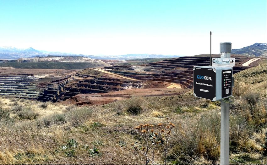
Installing GeoNet Wireless
  Data Hosting Systems

Topics Covered in this Tutorial Initial Setup Power Up Device Mounting & Network Considerations Connecting Sensors to Nodes Commissioning a Cellular Gateway Supervisor
Important Terms
Network
► A collection of GeoNet devices communicating via radio signals
► Minimum requirements for a working network: 1 “Node” ,
1 “Supervisor” , a PC with “Agent software” installed
Node
► Collects data from external sensors (piezometers, strain gauges, etc.)
and internal sensors (battery, signal strength, etc.)
► Forwards collected data to the Supervisor
► Will forward data from other Nodes to the Supervisor as necessary
Supervisor
► Controls the network (sets time, changes modes, etc.)
► Central collection point for all data obtained by the network
► Contains internal sensors for battery, signal strength, etc.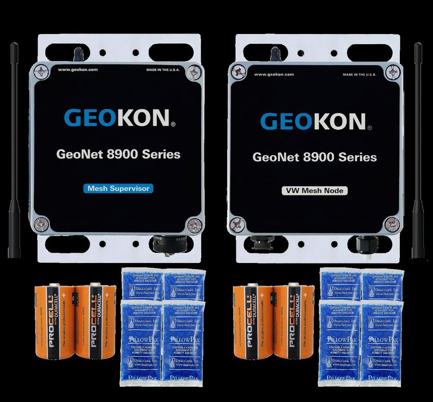
Important Terms (Continued)
Agent software
► Used for network configuration and data collection
► Data can be viewed as a chart or exported for use in other data
management applications
► Visit GEOKON.com/software to download
LED indicators
► Red and green LEDs that indicate the status of the device
► A key printed below the indicators explains the various light codes
Status Button
► Press to have the LED indicators display the device status
► Used to activate or restart “Deployment mode” on the Supervisor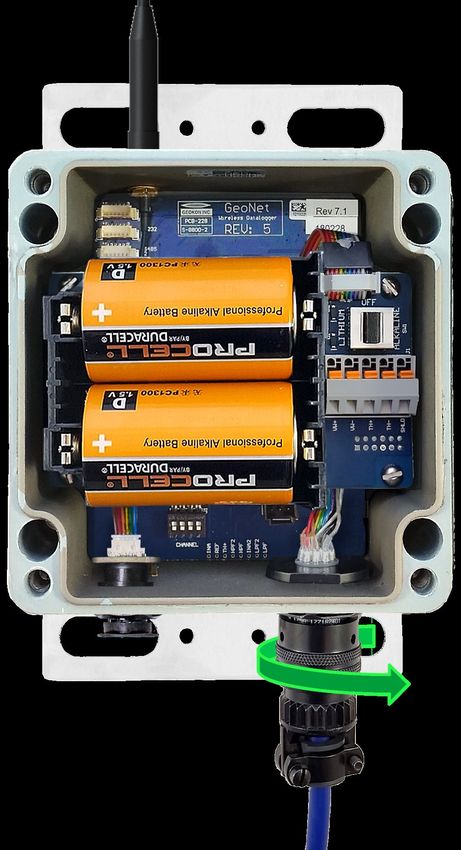
Important Terms (Continued)
Deployment mode
► Must be used when making changes to a network
(adding Nodes, changing batteries, resetting a device, etc.)
► Indicated by the LEDs on the Supervisor flashing every 10-15
seconds
► Automatically activated when Supervisor is powered
► Active for 60 minutes by default
(Can be changed using Agent software)
► Can be reactivated/reset by pressing the status button on
the Supervisor
(May take up to 6 minutes to take effect)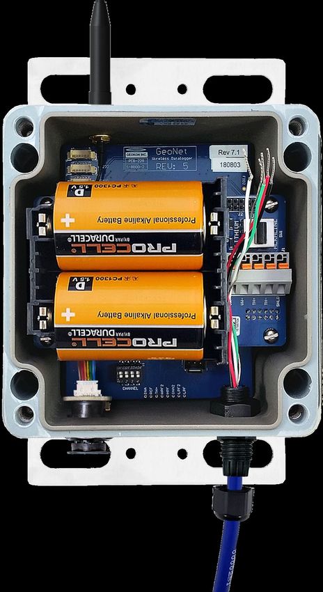
Items Required for Installation
GEOKON Provided
► #3 Philips head screwdriver
► Small flat head screwdriver
► Antenna for each device (Not required for Cellular Gateway
Supervisors)
► Two D-cell batteries for each device (Not required for Cellular
Gateway Supervisors)
► Desiccant packs
► Mini USB to standard USB cable (Required for Supervisors without
cellular capability)
► USB to RS-232 adaptor (Required for RS-232 Supervisors without
cellular capability)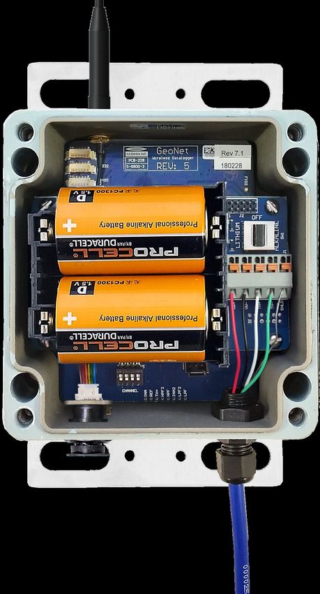
Items Required for Installation
Customer Provided
► Mounting hardware
(screws, U-bolts, hose clamps, etc.)
► Materials to create a suitable earth ground
(A 6-foot copper rod and 12 AWG or larger copper wire
are recommended; these items can be purchased from
GEOKON)
► Portable PC with Agent software installed
(Required on installation site when using a Supervisor
that does not have cellular capability)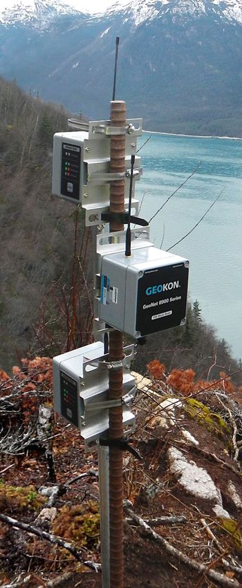
Getting Started
For ease of setup GEOKON recommends the following:
Perform the installation in the designated order
(Skipping steps or performing them out of order, could
complicate the installation of the network)
All network components should be in close proximity to one
another during the initial setup
Make sure all components have joined the network before
moving them to their final locations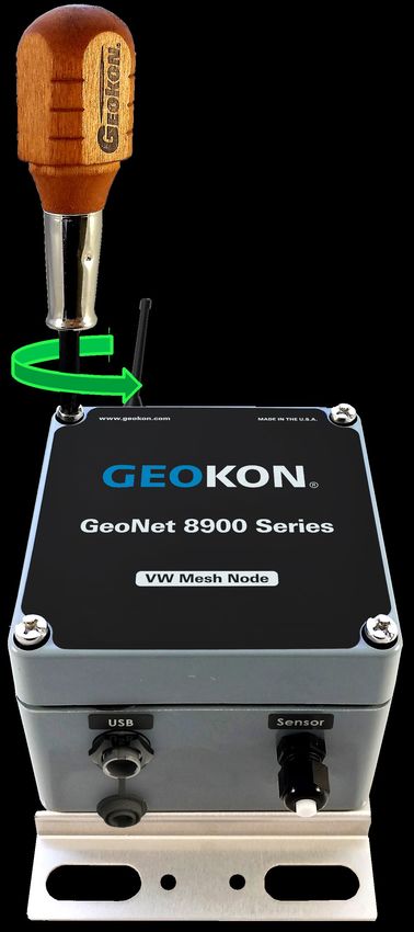
Initial Setup
Attach the Antennae

Complete the following for all
devices in the network:
1. Remove the cap from the
  antenna mount
2. Position   the antenna on the
  mount
3. Thread  the antenna onto the
  mount by rotating it clockwise
  until finger tight

 Do not cross thread the antenna. Cellular Gateway Supervisor
 antennae have an O-ring which must be flush with the enclosure
Remove the Covers

Complete the following for all devices
in the network:
1. Usinga Phillips head screwdriver,
  loosen the cover screws by turning
  them counterclockwise
2. Remove   the cover
Setting Channels
All GeoNet devices are set to operate on the same channel at
the factory
Channels only need to be set if multiple networks will be
operating within radio range of one another
Networks within radio range of one another must be set to
different channels
Up to 12 networks can operate in the same area, by utilizing a
different channel for each networkSetting Channels (Continued)
To set the channel, move the
channel dipswitches to one of
the 12 valid settings shown
GeoNet Devices will only
communicate with others that
have been set to the same
channel, therefore,
ALL DEVICES in a network
must be set to the same
channelPower Up
Powering a Cellular Gateway
Supervisor
1. Plug the AC adaptor, or other
external power source, into
the 9-24V DC power jack
(Cellular Gateways must have
an external power source)
2. Move the power switch to
BATTERY or 9-24V based on
the table below
Geographical Zone
Power Source Temperate Sub Polar
Mains / Solar with External Battery 9-24V
Battery
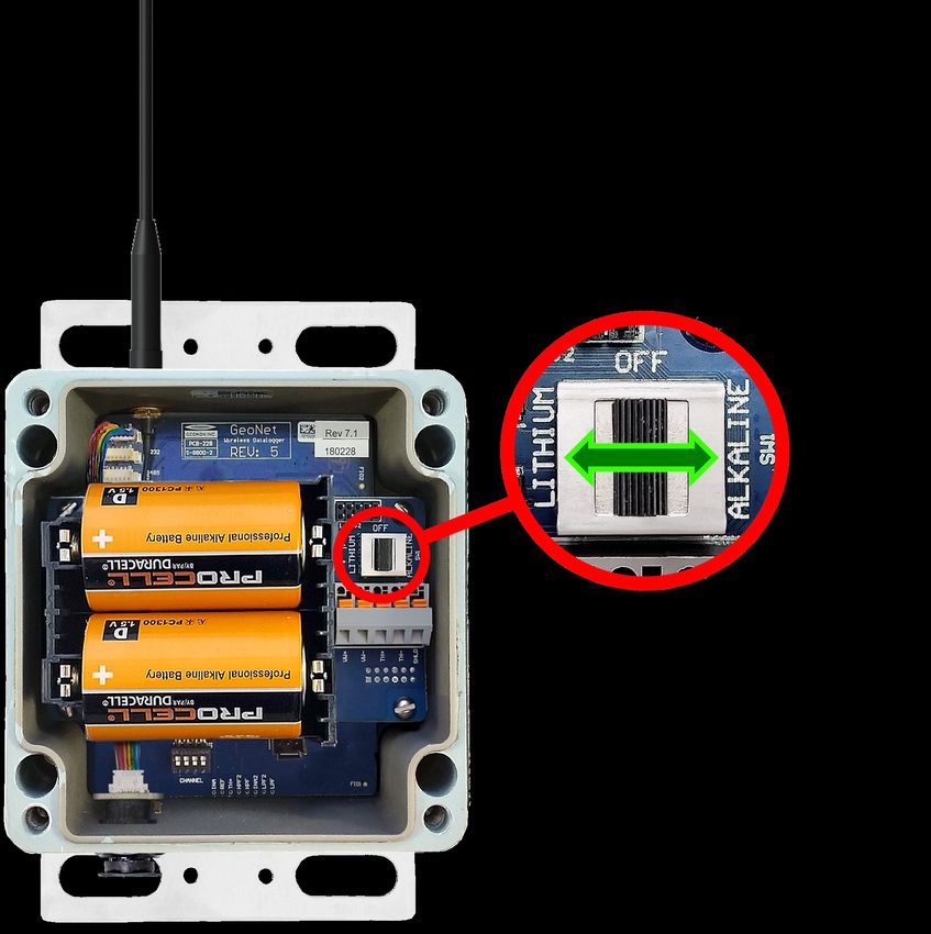
Solar, NO External Battery N/APowering a Supervisor without
Cellular Capability
1. Align the positive (+) side of
the D cell batteries with the
left side of the battery holder
2. Push
the batteries straight
down into the holder
3. Move the battery selector
switch to “ALKALINE” or
“LITHIUM” depending on the
type of batteries installedPowering the Supervisor
All Models
On power up, the green LED
on the side of the enclosure
will flash twice
(May take several seconds to
occur)
The LEDs will not flash again
until at least one Node has
joined the network, or the
status button is pressedClose the Supervisor
1. Placethe supplied desiccant packs
inside the enclosure
2. Make sure the cover gasket and the
mating ridge on the enclosure are
clean, and that the gasket is
properly seated inside the groove
3. Placethe cover on the unit, making
sure the orientation is correct
4. Tighten
the cover screws a little at a
time, working in a diagonal pattern
5. Check that the cover has closed
tightly and evenlySetting the Network Time
(Not Necessary for Cellular Gateway Supervisors)
Data will not be collected until
the network time has been set
using Agent software
1. Connect the Supervisor to a
computer using the factory
supplied USB cable (and RS-
232 adaptor if required)
2. Use Agent software to set the
network time
(For more information,
refer to the Agent tutorial, or
refer to the Agent instruction
manual)Verify Network Time is Set and
Record the Serial Number
1. Verify the network time is set by pressing
the status button and observing a green
and red flash on the LED indicators
2. If only the red LED flashes:
► Cellular Gateway Supervisors:
Wait several minutes then try again
► Supervisors without cellular capability:
Set the network time in Agent as
previously described
3. Record the serial number of the Supervisor
(Required to commission Cellular Gateway
Supervisors and used by Agent software to
differentiate networks)Power a Node
Nodes should be powered up
in close proximity to the
Supervisor
1. Align the positive (+) side of
the D cell batteries with the
left side of the battery holder
2. Push the batteries straight
down into the holder
3. Move the battery selector
switch to “ALKALINE” or
“LITHIUM” depending on the
type of batteries installedPower the Node (Continued)
3. The green LED on the Node will
flash twice (may take several
seconds to occur)
4. The Node will join the network in
approximately 30 seconds
(May take longer if Supervisor is
not in Deployment mode)
5. TheLEDs on the Supervisor and
Node will begin flashing in
unison
6. Verify
that the LEDs on the Node
and the Supervisor are flashing
green only before continuingAdding More Nodes
Each time a new Node joins
the network, the 60-minute
Deployment mode timer will
reset
The amount of time Deployment
mode is active can be changed
using Agent software
Deployment mode can be
reactivated/reset by pressing
the status button on the
Supervisor
(May take up to 6 minutes to
take effect)Adding More Nodes (Continued)
If a Node does not join the
Network within 30 seconds of
power up, it is out of range,
on the wrong channel, or the
Supervisor has left
deployment mode
Move Nodes to their final
location after they have joined
the network
(Ensures proper hardware
configuration before moving
away from the Supervisor)Device Mounting & Network Considerations
Device Mounting
GeoNet Devices can be mounted A B
using bolts (A), screws (B),
hose clamps (C), U-bolts (D), etc.
(Mounting hardware not included)
Always mount GeoNet devices
vertically, with the antenna
pointing up
C D
The space around the antenna
should be free of obstructions
A minimum mounting height of
two meters (six-feet) is
recommendedTiltmeter Node Orientation
The direction of tilt for the A and
B axes is shown on the cover of
the unit
Both axes have a range of ±90°,
based on a starting position of 0°
To achieve the best linearity,
mount the tiltmeter so that the
back of the enclosure is as close
as possible to vertical, and the
bottom of the enclosure is as
close as possible to horizontalDevice Grounding
GeoNet Devices should be A B
properly grounded to protect
against lightning and other
large transient voltages
All GeoNet devices can be
grounded by connecting a
suitable earth ground to the
mounting bracket (A)
Cellular Gateway Supervisors
and Multi-channel Nodes can
also be grounded via the
copper ground lug on the
bottom of the enclosure (B)Network Considerations
Start with Nodes closest to
the Supervisor and work
outwards
Place the Supervisor in the
center of the network
wherever possibleNetwork Considerations (Continued)
GeoNet devices can only
communicate with other
devices that are within range
of their radio signal
Radio ranges vary by model
and can be affected by the
radio environment and
obstructions
See the GeoNet manual for
complete radio specificationsNetwork Considerations (Continued)
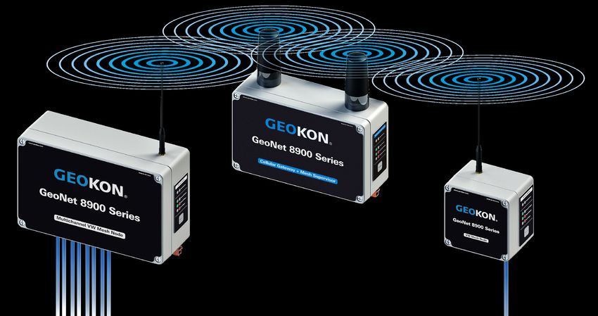
Nodes can communicate with the
Supervisor over greater distances
and work around obstacles by
using other Nodes as repeaters
Nodes automatically relay data as
necessary to reach the Supervisor
Each transmission from Node to
Node, or from a Node to the
Supervisor is known as a “Hop”
Up to four Hops can be made
between a Node and the
SupervisorNetwork Considerations (Continued)
GeoNet automatically
minimizes the number of
hops each Node uses by
bypassing Nodes which are
not needed as repeatersNetwork Considerations (Continued)
Obstructions between,
around, or near GeoNet
devices can cause reflections
of the radio signal
Reflected radio signals can
cause GeoNet devices to
malfunction
For optimum performance,
create as much space as
possible between the straight-
line radio path and any
obstructions (especially
metallic objects)Device Mounting (Continued)
Common mounting mistakes
include:
► Not enough clear space
around the antenna
► Mounting devices horizontally
► Metallic objects nearby
The photos to the right show
examples of improper device
mountingConnecting Sensors to Nodes
Connecting Sensors to Nodes
Depending on the model of the Node, sensors are connected by
either a bulkhead connector (A) or bare leads (B)
A
BConnecting Sensors to Nodes:
Bulkhead Connectors
1. Remove the cap from the
bulkhead connector on the Node
by rotating it counterclockwise
2. Align the grooves of the two
connectors and then push them
together
3. Twist the outer ring clockwise
until it locks into placeConnecting Sensors to Nodes:
Bare Leads
1. Loosenthe cable gland nut and
remove white plastic dowel
2. Slide
the cable of the sensor
through the cable gland (and
gland nut) and into the NodeConnecting Sensors to Nodes:
Bare Leads (Continued)
3. Wire each conductor into the terminal block by pressing down
on an orange tab, inserting the bare end of the conductor into
the terminal block, and then releasing the tab
Conductors are wired as follows:
Vibrating Wire Sensors Addressable (RS-485) Sensors
RED =
BLACK = VW– GREEN = 485–
RED = 12V
GREEN = TH– BLACK = GND
To prevent possible short circuits, do not allow bare leads to
touch each other during or after wiring; trim long leads if
necessaryConnecting Sensors to Nodes:
Bare Leads (Continued)
4. Gently
pull on each conductor to
make sure it is secure
5. Tightenthe nut onto the cable
gland until the gland firmly grips
the outer jacket of the cable
The cable gland must be properly
tightened to prevent water entry
(Do not over-tighten, which may
strip the plastic threads)
6. Gentlypull on the sensor cable to
make sure it is held in place by
the cable glandNotes Concerning Multi-Channel
and Addressable Nodes
On Multi-channel Nodes, sensor cables should be inserted into
the cable glands in order from left to right and wired in
sequence, starting with Channel 1
Wire sensors into the “VW” terminal blocks only
(Not the blocks marked “485_IN” and “485_OUT”
Multi-channel and addressable Nodes stop trying to read empty
channels after two attempts; additional attempts occur at the
top of every hour (Reset the Node to initiate an immediate retry)Close the Node and Record Serial
Numbers
1. Insertthe supplied desiccant packs
into the enclosure
2. Install
the cover as previously
explained
3. Recordthe serial number of the
Node and the attached sensor
(For Multi-channel Nodes, note the
channel each sensor has been wired
into)Commissioning a Cellular Gateway
SupervisorCellular Gateway Commissioning
Complete the Network installation before commissioning the
Supervisor (Devices added after the initial commissioning has
taken place may need to be commissioned to function properly)
1. Go to api.geokon.com
2. Click “Create user”, enter the required information,
and then click “Submit”Cellular Gateway Commissioning (Continued) 3. Log in using the newly created user account 4. Click “add account” 5. Click “create new account”
Cellular Gateway Commissioning
(Continued)
6. Enter   the required information, and then click “submit”

7. Clickon the “Devices” tab, enter the serial number of the
  Cellular Gateway Supervisor and then click “Register Device”
Cellular Gateway Commissioning
(Continued)
8. Click   the edit button to open the settings for the Cell Gateway

9.   Activate the cellular service by moving the switch to the right
Cellular Gateway Commissioning
(Continued)
10. Click
        the “Connections” tab, then enter a token name (can be
   anything) and click “Create Token”

11. Click   on the Token to copy the alphanumeric code

12. Thecopied token can be used in Agent (and other compatible
   data visualization software) to connect to the Supervisor
For more information…
Consult the GeoNet and Agent instruction manuals.
Instruction manuals are available for download at:
www.geokon.com/Manuals
Please visit https://www.geokon.com/Tutorials for more tutorials
The GEOKON® logo and word mark are registered trademarks with the United States Patent and Trademark Office. GEOKON maintains an ongoing policy of design review and reserves the right to amend products and specifications without notice.
©GEOKON. All Rights Reserved. | Rev-C-1/25/2021You can also read