Installation Tips and NEC-2020 Updates
←
→
Page content transcription
If your browser does not render page correctly, please read the page content below
Ground-Fault Circuit Interrupter
               (GFCI) Protection
               Installation Tips and NEC-2020 Updates
                                                By David A. Smith

10   IAEI MAGAZINE   JANUARY ● FEBRUARY 2020   WWW.IAEIMAGAZINE.ORG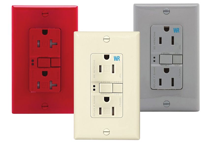
T
he expansion of ground-fault circuit-interrupter An unintentional, electrically conductive connection
(GFCI) protection in the 2020 National Electrical between an ungrounded conductor of an electrical
Code® (NEC®) is a step toward increasing circuit and the normally non–current-carrying
electrical safety regarding electric shock conductors, metallic enclosures, metallic raceways,
protection. To fully grasp this update to the code, one metallic equipment, or earth.
must understand the requirements and functionality of
this technology for installation and inspection purposes. We can understand now that GFCI is a device
Where did it come from? How to have a code-compliant protecting personnel by de-energizing a circuit after
installation? We will cover all these questions, but an an unintentional, electrically conductive connection
explanation behind the technology behind GFCI must provides current to ground at a set amount for a
come first. particular duration of time. This path of unintentional
current could be through the human body, thus the
WHAT IS A GFCI? necessity of GFCI protection to prevent electrocution.
The ground-fault circuit-interrupter, according to NEC- The informational note from the GFCI definition also
2020 Article 100: states that it de-energizes the circuit with a ground fault
current at 6mA or higher and will keep the circuit active
A device intended for the protection of personnel that for a ground-fault current less than 4mA. Ground-fault
functions to de-energize a circuit or portion thereof circuit-interrupters are governed by harmonized product
within an established period of time when a ground- standards from Underwriters Laboratories, Inc. (UL 943)
fault current exceeds the values established for a Class and the Canadian Standards Association (CSA C22.2
A device. No.144.1).
Informational Note: Class A ground-fault circuit THE NEC ON GFCI
interrupters trip when the ground-fault current is 6 mA Ground-fault circuit-interrupters are covered in Article
or higher and do not trip when the ground-fault current 210 of the NEC covering branch circuits. In 210.8, Ground-
is less than 4 mA. For further information, see UL 943, Fault Circuit-Interrupter Protection for Personnel, the
Standard for Ground-Fault Circuit Interrupters. 1 Code provides the locations where GFCIs are required
to protect the branch circuit. In parts 210.8(A) through
There are a few different key points to uncover in the (F), the NEC covers the mandated protections in dwelling
Article 100 definition. First, a GFCI is a device intended units, areas other than dwelling units, crawl space
for the protection of personnel. How does it protect lighting outlets, specific appliances, equipment requiring
personnel? The technology is designed to de-energize servicing, and outdoor outlets. According to the new
a circuit within a set threshold of time when a ground- NEC-2020 for 210.8(A), Dwelling Units:
fault current reaches a particular magnitude. What is a
ground-fault? According to the NEC-2020:
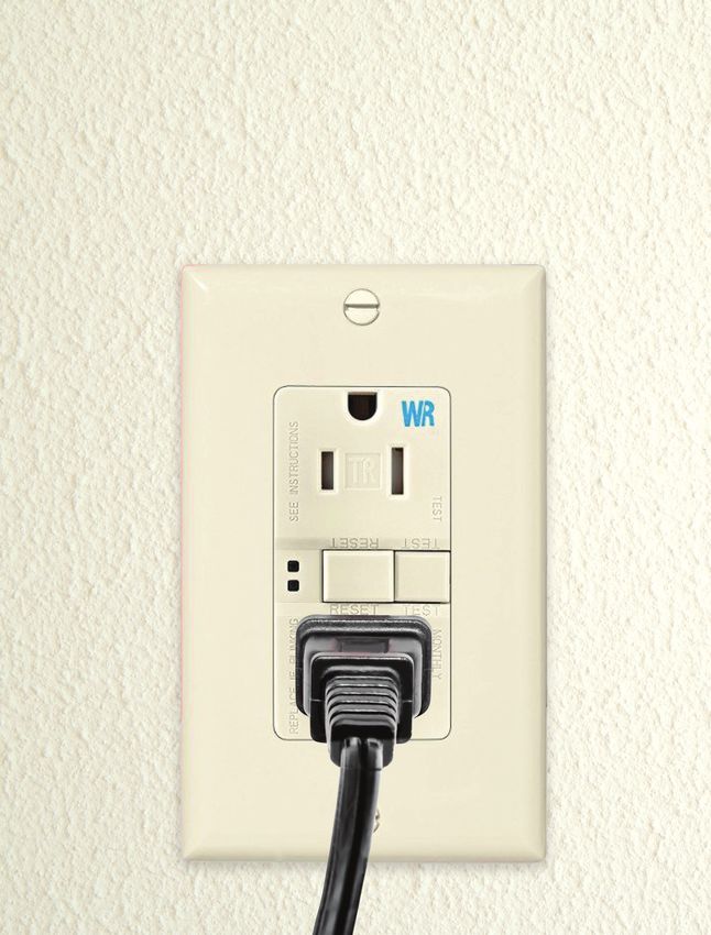
Figure 1. GFCI Receptacle Features
WWW.IAEIMAGAZINE.ORG JANUARY ● FEBRUARY 2020 IAEI MAGAZINE 11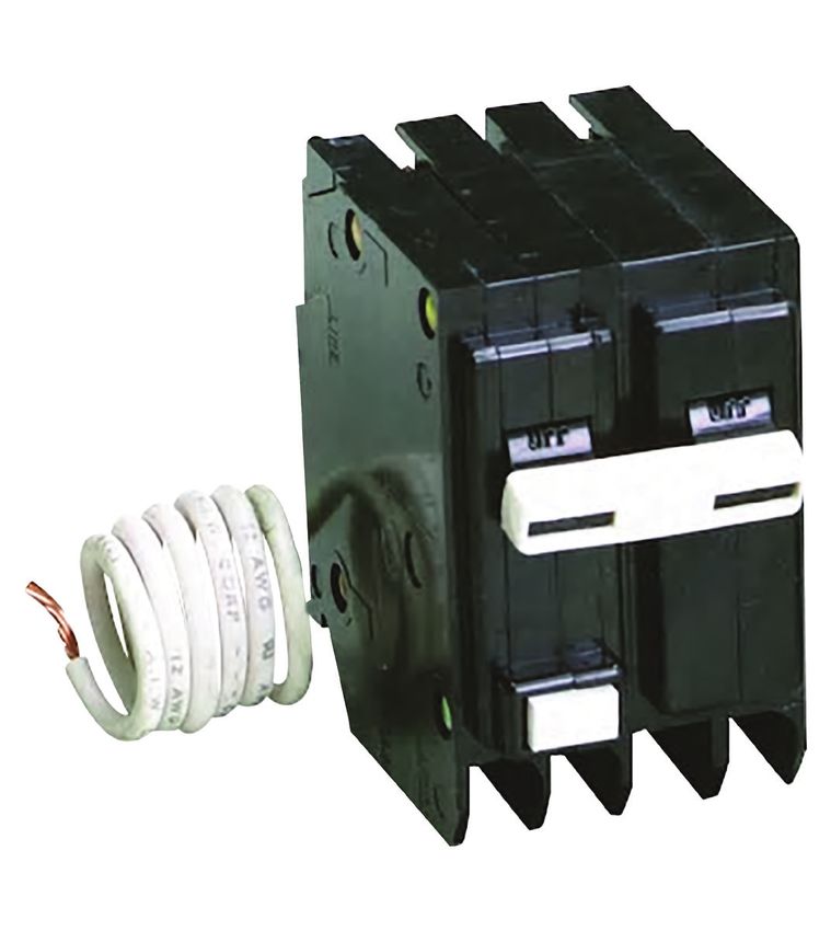
“All 125-volt through 250-volt receptacles installed in       covered in NEC 2017. This now requires 250V receptacle
     the locations specified in 210.8(A)(1) through (12) and       loads in the areas listed in 210.8(A)(1) through (A)(11) and
     supplied by single-phase branch circuits rated 150            210.8(B)(1) through (B)(12), such as appliances like electric
     volts or less to ground shall have ground-fault circuit-      clothes dryers, welders, and electric ranges (within 6ft of
     interrupter protection for personnel.”                        the sink) will require GFCI protection.
                                                                       Another key code update to the 2020 NEC pertaining
    The NEC goes on to list the following required branch          to 210.8 in general:
 circuit locations to be protected by GFCI technology:
 bathrooms, garages, outdoors, crawl spaces, basements,               “For the purposes of this section, when determining
 kitchens (countertop receptacles), sinks (within 1.8 m,              the distance from receptacles, the distance shall be
 6 ft), boathouses, bathtubs, laundry areas, and indoor               measured as the shortest path the supply cord of an
 damp and wet locations. The Code also requires that                  appliance connected to the receptacle would follow
 GFCI protection shall be installed in a readily accessible           without piercing a floor, wall, ceiling, or fixed barrier, or
 location. The definition from the NEC-2020 for a readily             the shortest path without passing through a window.”
 accessible location is:
                                                                      This language used to include doorways as an
     “Accessible, Readily (Readily Accessible). Capable            exception to the measurement requirements. The NEC
     of being reached quickly for operation, renewal, or           2020 has removed the doorway portion to now include
     inspections without requiring those to whom ready             receptacles within the mandated distance to have
     access is requisite to take actions such as to use tools      ground-fault circuit-interrupter protection regardless of
     (other than keys), to climb over or under, to remove          whether there is a doorway within the path of the supply
     obstacles, or to resort to portable ladders, and so forth.”   cord. This change means that, for example, the receptacle
                                                                   located outside the bathroom whether in a hallway or
    There are a few updates to the GFCI code requirements          bedroom, if within 6 ft of the inside edge of the sink,
 from the development of the 2020 edition of the NEC.              would be required to have GFCI protection.
 One key update is GFCI is now required to protect 125-
 volt to 250-volt receptacles supplied by single-phase             CODE COMPLIANT INSTALLATION
 branch circuits rated 150 volts or less to ground from the        While 210.8 covers what areas shall be protected by
 former 125-volt, single-phase, 15- and 20-amp receptacles         GFCI technology, it does not cover the specifics of
                                                                   how to be compliant. The final judgment lies with the
                                                                   authority having jurisdiction (AHJ). The most common
                                                                   practice to be compliant with the GFCI requirements

 Figure 2. Single-Pole GFCI Breaker                                Figure 3. Double-Pole GFCI Breaker

12    IAEI MAGAZINE    JANUARY ● FEBRUARY 2020                                                              WWW.IAEIMAGAZINE.ORG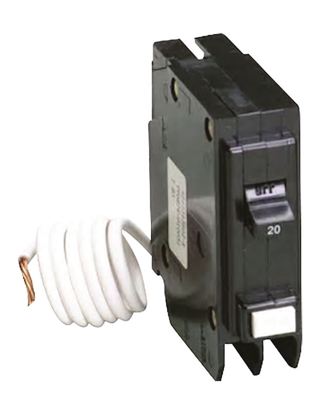
Figure 4. GFCI Tamper-Resistant Receptacles. Hospital Grade (left) and Weather-Resistant (center, right)

is to install a UL 943 Listed Class A circuit breaker or                      work practices per NFPA® 70E. (NOTE: This installation
receptacle to protect the required outlets and appliances.                    procedure is for a two-pole circuit breaker featuring two
You can ensure the device is listed as UL 943 Class A                         “hot” legs. A grounded conductor is not needed in this
by its mandated factory marking. While installing the                         type of installation such as with an air conditioner.)
device, be sure to note the manufacturer recommended                             1. Turn off main breaker.
connection methods and terminal torque values. The                               2. Move the handle of the GFCI to “OFF.”
terminal torque values are listed either on the device or                        3. Connect the ground wire (green or bare) of the
in the installation instructions. If the torque value cannot                         circuit to be protected to the ground lug or bar in
be determined, NEC 110.14(D) has an informational note                               the end use equipment. Torque per ground bar/lug
that guides you to contact the manufacturer or refer to                              requirements.
Annex I which provides information from UL 486A-486B                             4. Connect the white (neutral) load wire of the
for the torque values. A loosely-terminated conductor                                circuit to be protected to the wire connector of
can increase the risk of a hazard.                                                   the GFCI marked “Load Neutral.” Torque the lug
    There are distinct differences in GFCI protection                                screw per torque requirements listed on the side
when installing a circuit breaker or receptacle. A GFCI                              of breaker. Neutral connection is optional for 208
circuit breaker will provide GFCI protection to the                                  V and 240 V systems.
entirety of the branch circuit including the “home                               5. Connect the “hot” (black or red) wire(s) of the
run.” With a receptacle application, the installer has                               circuit to be protected to the wire connector(s)
the decision to provide GFCI protection to loads in the                              of the GFCI marked “Load Power.” Torque lug
circuit downstream of the receptacle or to only the                                  screw per torque requirements listed on the side
individual receptacle. There are also different variations                           of breaker.
of GFCI receptacles such as hospital grade and weather-
resistant that feature tamper-resistant systems inside of                        Proper Installation Method for GFCI Receptacle
the receptacle.                                                               for Individual Load Protection: (Follow electrical safe
                                                                              work practices per NFPA® 70E.)
Proper Installation Method for GFCI                                              1. Turn off main breaker.
Circuit Breaker:                                                                 2. Connect the LINE cable wires to the LINE
The installation procedure is the same for both single-                              terminals:
and two-pole ground fault interrupters except for the                                • The white wire connects to the White terminal
additional load power connection required for the two-                                 (Silver)
pole GFCI. Before installing a GFCI, disconnect all                                  • The black wire connects to the Hot terminal
power supplying this equipment. Follow electrical safe                                 (Brass)

WWW.IAEIMAGAZINE.ORG                                                                                  JANUARY ● FEBRUARY 2020   IAEI MAGAZINE   13
3.   Connect the grounding wire (only if there is a       a ground-fault which should trip the protecting device.
          grounding wire):                                     These GFCI protecting devices may also have LEDs to
          • For a box with no grounding terminal: Connect      provide further visual indication of a trip or an “End of
            the LINE cable’s bare copper (or green) wire       Life” scenario. “End of Life” is a feature that self-tests the
            directly to the grounding terminal on the GFCI     device to ensure that GFCI protection is being provided to
            receptacle.                                        the branch circuit. If the GFCI protection has expired or
          • For a box with a grounding terminal: Connect       malfunctioned, the End of Life LED will indicate this status.
            a 6-inch bare copper (or green) 12 or 14 AWG       Refer to the manufacturer product documentation to learn
            wire to the grounding terminal on the GFCI.        more about the device’s Supervisory and End of Life tests.
            Also connect a similar wire to the grounding          It is recommended that both the installer and
            terminal on the box. Connect the ends of these     inspector of GFCI installations perform the Supervisory
            wires to the LINE cable’s bare copper (or green)   Test as well as noting the status of the visual indication
            wire using a wire connector. If these wires are    LEDs to verify proper installation. UL 943 also requires
            already in place, check the connections.           the product to have the Supervisory Test procedure
     4.   Complete the installation:                           completed on a monthly schedule which would be the
          • Fold the wires into the box, keeping the           owner’s regular maintenance responsibility.
            grounding wire away from the White and Hot
            terminals. Screw the receptacle to the box and
            attach the faceplate.

    Proper Installation Method for GFCI Receptacle
 for Downstream Branch Circuit Protection: (Follow
 electrical safe work practices per NFPA® 70E.)
    1. Turn off main breaker.
    2. Connect the LINE cable wires to the LINE
         terminals:
         • The white wire connects to the White terminal
           (Silver)
         • The black wire connects to the Hot terminal
           (Brass)
    3. Connect the LOAD wires to the LOAD terminals:
         • The LOAD white wire to the LOAD White
           terminal.
         • The LOAD black wire connects to the LOAD
           Hot terminal.
    4. Complete the installation:
         • Fold the wires into the box. Screw the receptacle   Figure 5. Manufacturer Installation and Testing Sheet (Stuffer Sheet)
           to the box and attach the faceplate.
                                                               SUMMARY
 GFCI INSTALLATION INSPECTION                                  Ground-fault circuit-interrupter protection has been
 As previously stated, the most common practice on             providing a safer environment for installers, inspectors,
 compliance with the GFCI code requirements is to install      and consumers since introduced in the NEC for dwelling
 a UL 943 Listed Class A circuit breaker or receptacle to      units nearly fifty years ago. Having a grasp on where
 protect the required outlets and appliances.                  GFCI is required in the code and the best practices for
    In order to be listed under UL 943, the device must        installation enables electrical industry professionals
 have a “Supervisory Test” to enable the ability of manually   to take full advantage of the technology and its many
 testing the tripping mechanism. On both circuit breakers      applications. The latest expansion of GFCI in the NEC-
 and receptacles, the Supervisory Test is adhered to by        2020 only looks to further advance safety of the industry
 providing a push button often labeled “TEST.”                 and the public from electrical hazards.
    The device must have an audible or visual indication
 that the test is performed. Receptacles commonly have            1. NFPA 70®, National Electrical Code®, 2020 edition.
 an LED located on the face visually indicating the            Copyright© 2019, National Fire Protection Association.
 tripping mechanism. Circuit breakers will trip the handle     For a full copy of NFPA 70®, please go to www.nfpa.org.
 to provide visual indication. Both receptacles and circuit
                                                               David Smith is a Codes & Standards Specialist for the Eaton Residential and Wiring Devices
 breakers have added options for an audible indication of      Division. He supports product lines for Circuit Protection, Wiring Devices, Load Centers and
 tripping mechanisms for applications where both audible       Metering. David is responsible for supporting our Codes & Standards strategic initiatives for
                                                               product and installation standards such as UL and NEC®. He will also support our marketing
 and visual indication is necessary.                           efforts with the creation of industry white papers and trade publication articles. David holds
                                                               a B.S. Electrical Engineering and a Masters in Business Administration from West Virginia
    On receptacles that are downstream to their GFCI           University. Prior to joining Eaton, he worked at an Architecture and Engineering firm doing
 protection, a GFCI-testing tool can be used to simulate       design and inspections of various electrical power systems.

14    IAEI MAGAZINE   JANUARY ● FEBRUARY 2020                                                                               WWW.IAEIMAGAZINE.ORG
You can also read