Valve block VB 25 Assembly and operating manual - Translation of the original manual
←
→
Page content transcription
If your browser does not render page correctly, please read the page content below
Translation of the original manual

Valve block
VB 25
Assembly and operating manual

                 Superior Clamping and Gripping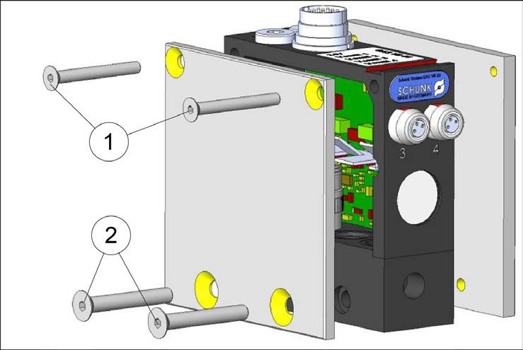
Imprint

                                Imprint

    Copyright:
    This manual remains the copyrighted property of SCHUNK GmbH & Co. KG. It is solely
    supplied to our customers and operators of our products and forms part of the product.
    This documentation may not be duplicated or made accessible to third parties, in particu-
    lar competitive companies,
    without our prior permission.
    Technical changes:
    We reserve the right to make alterations for the purpose of technical improvement.
    Document number: 0389614
    Edition: 01.01 |23/01/2014|en
    © SCHUNK GmbH & Co. KG
    All rights reserved.

    Dear customer,
    congratulations on choosing a SCHUNK product. By choosing SCHUNK, you have opted for
    the highest precision, top quality and best service.
    You are going to increase the process reliability of your production and achieve best
    machining results – to the customer's complete satisfaction.
    SCHUNK products are inspiring.
    Our detailed assembly and operation manual will support you.
    Do you have further questions? You may contact us at any time – even after purchase.

    Kindest Regards

    Yours SCHUNK GmbH & Co. KG
    Spann- und Greiftechnik
    Bahnhofstr. 106 – 134
    D-74348 Lauffen/Neckar
    Tel. +49-7133-103-0
    Fax +49-7133-103-2399
    info@de.schunk.com
    www.schunk.com

2              01.01|VB 25|en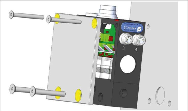
Table of contents

                                   Table of contents
1   About this manual .................................................................................................... 4
    1.1 Warnings ................................................................................................................... 4
        1.1.1 Key words ...................................................................................................... 4
        1.1.2 Symbols ......................................................................................................... 4
    1.2 Applicable documents .............................................................................................. 4
2   Basic safety notes .................................................................................................... 5
    2.1 Intended use ............................................................................................................. 5
    2.2 Environmental and operating conditions................................................................. 5
    2.3 Product safety........................................................................................................... 5
         2.3.1 Protective equipment ................................................................................... 6
         2.3.2 Constructional changes, attachments, or modifications .............................. 6
    2.4 Personnel qualification ............................................................................................. 6
3   Warranty .................................................................................................................. 7
4   Scope of delivery ...................................................................................................... 7
5   Accessories ............................................................................................................... 7
6   Technical data .......................................................................................................... 8
7   Electrical and pneumatic block diagram .................................................................... 9
8   Assembly ................................................................................................................. 10
    8.1 Installation notes .................................................................................................... 10
    8.2 Mechanical connection .......................................................................................... 11
        8.2.1 VB 25 valve block overview......................................................................... 11
        8.2.2 Valve block assembly .................................................................................. 13
        8.2.3 Assembly of a series of several valve blocks............................................... 14
        8.2.4 Connections on the VB 25 valve block ........................................................ 15
    8.3 Electrical connection .............................................................................................. 16
    8.4 Start-up ................................................................................................................... 17
9   Troubleshooting ...................................................................................................... 18
    9.1 24 V operating voltage display does not light up ................................................... 18
    9.2 Display for valve does not light up ......................................................................... 18
    9.3 24 V and valve display light up, valve does not switch supply pressure to the out-
        put........................................................................................................................... 18
    9.4 Valve block not tight when valves are switched off............................................... 19
10 Maintenance and Care ............................................................................................ 20

                                                                                                      01.01|VB 25|en                   3
About this manual

                     1 About this manual
                            This instruction is an integral part of the product and contains im-
                            portant information for a safe and proper assembly, commission-
                            ing, operation, maintenance and help for easier trouble shooting.
                            Before using the product, read and note the instructions, especial-
                            ly the chapter "Basic safety notes".

                    1.1 Warnings
                            The following key words and symbols are used to highlight dan-
                            gers.

                 1.1.1 Key words

      DANGER           Dangers for persons.
                       Non-compliance will inevitably cause irreversible injury or death.
     WARNING           Dangers for persons.
                       Non-compliance may cause irreversible injury or death.
      CAUTION          Dangers for persons.
                       Non-observance may cause minor injuries.
       NOTICE          Information about avoiding material damage

                 1.1.2 Symbols

                       Warning about a danger point

                       Warning about hand injuries

                       General mandatory sign to prevent material damage

                    1.2 Applicable documents
                             • General terms of business
                             • Catalog data sheet of the purchased product
                            The documents listed here, can be downloaded on our homepage
                            www.schunk.com

4          01.01|VB 25|en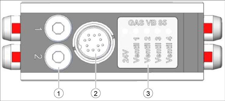
Basic safety notes
2 Basic safety notes
2.1 Intended use
The module is designed exclusively to control compressed air.
The product is intended for installation in a machine/system. The
requirements of the applicable guidelines must be observed and
complied with.
The product may be used only in the context of its defined applica-
tion parameters ( 6, Page 8).
The module is not a safety component in accordance with the EC
Machine Directive 2006/42/EC and must not be used in safety-
related parts of machine control units.
Any other use or use exceeding that specified is regarded as inap-
propriate use. The manufacturer assumes no liability for any re-
sulting damage.
2.2 Environmental and operating conditions
The module may be used only in the context of its defined applica-
tion parameters ( 6, Page 8).
2.3 Product safety
Dangers arise from the product, if:
• the product is not used in accordance with its intended pur-
pose.
• the product is not installed or maintained properly.
• the safety and installation notes are not observed.
Avoid any manner of working that may interfere with the function
and operational safety of the product.
Wear protective equipment.
NOTE
More information are contained in the relevant chapters.
01.01|VB 25|en 5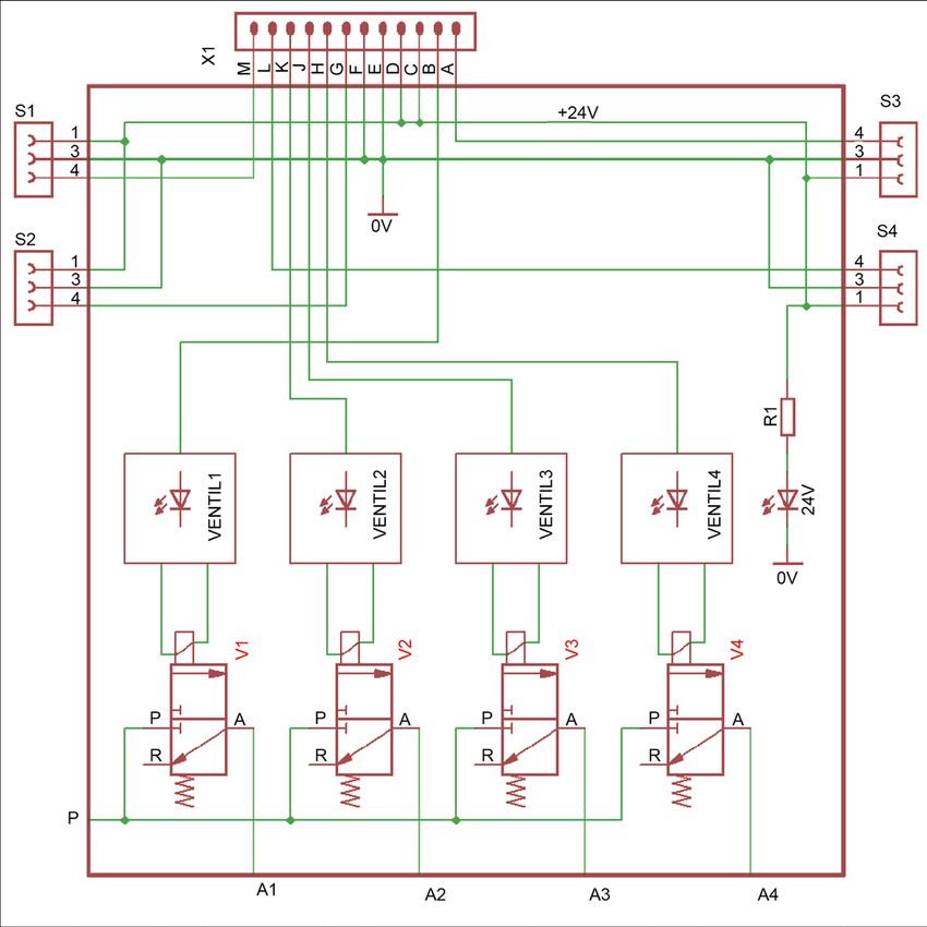
Basic safety notes
2.3.1 Protective equipment
Provide protective equipment per EC Machinery Directive.
2.3.2 Constructional changes, attachments, or modifications
Additional drill holes, threads, or attachments that are not offered
as accessories by SCHUNK may be attached only with permission
of SCHUNK.
2.4 Personnel qualification
The integration, assembly, initial start-up and maintenance of the
module as well as any repairs may only be performed by qualified
personnel.
Anyone assigned by the operating company with work on the
module must read and understand the complete assembly and
operating manual, in particular the chapter "Basic safety notes"
( 2, Page 5). This applies in particular to occasional personnel,
such as maintenance personnel.
The following work safety notes are to be observed in particular:
• The operator is obliged to inform the manufacturer immediate-
ly about any noticeable changes to the valve block which com-
promise safety.
• As a general rule, all work on the valve block is to be performed
only in shutdown mode. No electrical or pneumatic signals
must be present.
6 01.01|VB 25|enWarranty / Scope of delivery / Accessories
3 Warranty
The warranty is valid for 24 months from the delivery date to the
production facility under the following conditions:
• Intended use in 1-shift operation
• Observe the mandatory maintenance and lubrication intervals
• Observe the environmental and operating conditions
Parts touching the work piece and wear parts are not part of the
warranty.
4 Scope of delivery
The scope of delivery includes:
• Valve block VB in the ordered model.
5 Accessories
A VB25 accessory pack is required for each valve block.
Content of the accessories pack:
• Connection cable
• O-ring (14x1.5)
• G1/8 locking screw
A wide range of accessories are available for this module.
For information about which accessories can be used with the ap-
propriate product version ☞ catalog.
01.01|VB 25|en 7Technical data
6 Technical data
Size 25
Mechanical operating data
Weight [g] 450
Number of valves 2 to 4 MV 25 valves
Dimensions [mm] 85 x 85 x 28
Ambient temperature [°C]
Min. -15
Max. 40
Sealing material Viton - incompatible with hot water, steam,
amines, organic acids and polar solvents
Protection class IP 50 in installed condition with cover plate
Switching times [ms] 6 depending on the supply voltage
Electrical operating data
Operating voltage [V] 24 ± 10 %
Electrical connection M14 circular plug, 12-pin
Sensor connections Four M8 circular plugs, 3-pin, on the side. Two
sensor sockets at top upon request
Power consumption per valve Switch-on phase of 0 to 15 ms: 4.5 W power
drop after 15 ms: 2.5 W
Control inputs Input impedance level of 6.8 kΩ
Operating data for compressed air connection
Pressure medium Filtered compressed air, 40μm, dry, oil free,
compressed air purity classes ISO 8573-1 7 4 2
Function 3/2 directional control valve
Supply pressure range 2 to 8 bar. Other supply pressures upon re-
quest
Compressed air connection G 1/8
Nominal flow rate Qn 135 Nl/min per output according to ISO 6358
Leakage rate per valve [mNl/min] 8
Further technical data can be found in the catalog data sheet.
The most recent version applies.
8 01.01|VB 25|enElectrical and pneumatic block diagram
7 Electrical and pneumatic block diagram
Fig. 1
01.01|VB 25|en 9Assembly
8 Assembly
8.1 Installation notes
WARNING
Risk of injury when working on the module!
• Switch off the energy supply.
• Switch off the electrical and pneumatic signals.
NOTICE
The electronic components on the circuit board can be de-
stroyed by electrostatic discharge.
• Make sure the valve block is only touched by the metal frame
and the circuit board is not touched at all after removing the
ESD packaging for the assembly of the valve block.
NOTICE
Observe the requirements for the air supply.
( 6, Page 8) "Technical Data"
NOTE
The following procedure is to be strictly observed for the installa-
tion of the valve block:
• The valve cartridge and accessories are supplied separately and
must be assembled on site.
• The description of the installation is based on a fully equipped
valve block with MV 25 micro valves.
10 01.01|VB 25|enAssembly
8.2 Mechanical connection
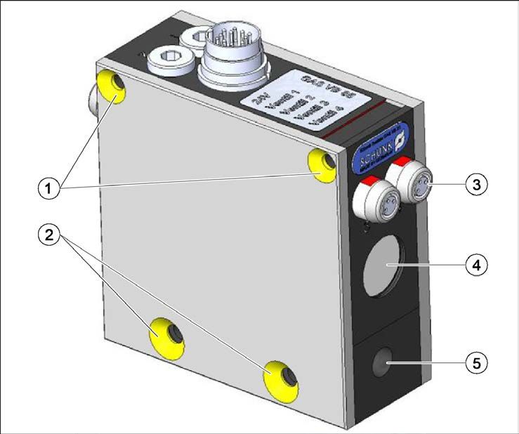
8.2.1 VB 25 valve block overview
Fig. 2
1 G1/8" locking screws for alternative position of the S1
and S2 sensor sockets
2 12-pin plug
3 Display field with indicator lights
01.01|VB 25|en 11Assembly
Fig. 3
1 2 x fixing bore for screw (M4 x 35)
2 2 x fixing bore for screw (M5 x 35)
3 M8 sensor sockets
4 Sound absorber for exhaust air R
5 Supply air connection P
12 01.01|VB 25|enAssembly
8.2.2 Valve block assembly
Fig. 4
NOTICE
The 14 x 1.5 O-ring for the air feed-through can fall out.
• Check whether the O-ring is there before applying the cover
plate.
The valve block is mounted in the control cabinet or machine / au-
tomated system with the mounting screws (2 x M5 x 35 and 2 x
M4 x 35, ISO 10642). The cover plate on the front side serves as
housing end plate.
Fig. 5 Valve block drilling pattern
01.01|VB 25|en 13Assembly
8.2.3 Assembly of a series of several valve blocks
Fig. 6
1 Unscrew the screws (1) with a 2.5 mm Allen key and the
screws (2) with a 3.0 mm Allen key.
2 Remove the valve cover from both sides.
NOTICE
The 14 x 1.5 O-ring for the air feed-through can fall out.
• Check whether the O-ring is there before connecting the valve
blocks.
3 Connect the valve blocks by means of "metal/guide rods".
4 Integrate the VB 25 multiple block in the machine/automated
system or control cabinet with connecting elements/screws.
Several valve blocks can be connected to each other. Each block
can be supplied by the central pressure supply in the event of a
multiple series connection.
14 01.01|VB 25|enAssembly
8.2.4 Connections on the VB 25 valve block
Fig. 7
1 Feed-through P 2 Connection P
Install the compressed air supply (G1/8 thread size).
The compressed air supply is possible from both sides. Seal unused
supply openings with a locking screw.
The compressed air supply is transferred from valve block to valve
block through a through-bore.
01.01|VB 25|en 15Assembly
8.3 Electrical connection
NOTICE
Damage to the valve block due to a faulty electrical connection!
Observe the maximum values of the electrical supply ( 6, Pa-
ge 8).
Fig. 8
Designation Color Pin no. Level
+24 V gn C 24 V ± 10 %
+24 V ye D 24 V ± 10 %
GND gr E 0V
GND pk F 0V
Switching signal, bn B Inactive = 0 V..2 V
valve 1 Active = 4 V.. 26 V
Switching signal, pr K Inactive = 0 V..2 V
valve 2 Active = 4 V.. 26 V
Switching signal, bk J Inactive = 0 V..2 V
valve 3 Active = 4 V.. 26 V
Switching signal, rd H Inactive = 0 V..2 V
valve 4 Active = 4 V.. 26 V
Sensor output 1 rdbu M Sensor signal
Sensor output 2 bu G Sensor signal
Sensor output 3 wh A Sensor signal
Sensor output 4 grpk L Sensor signal
1 Mount 12-pin circular plug for power supply.
16 01.01|VB 25|enAssembly
Fig. 9 Sensor socket view on plug side
1 +24 V 3 GND 4 Signal
2 Mount circular plug for the sensors.
The connection assignment of the M8 sensor socket on the valve
block corresponds to the standard connection assignment of a 3-
pin sensor.
8.4 Start-up
WARNING
Risk of injury due to objects falling or being ejected from the
machine/automated system!
• Check whether all screw connections are tight prior to the
start-up or restart.
The valve block with a pressure range of 2 - 8 bar requires a
minimum supply pressure of 2 bar in order to switch the valves.
1 Create the supply pressure within the pressure range of the
valve (see data sheet/catalog).
2 Apply the operating voltage (☞ data sheet/catalog).
3 Switch on switching signals 1 to 4.
The supply pressure is put through to the valve outlet of the
actuated valves.
4 Switch off switching signals 1 to 4.
The valve outlet is separated from the supply pressure and,
in the case of 3/2 directional control valves, is ventilated by
means of the lateral sound absorbers in the valve block
housing.
01.01|VB 25|en 17Troubleshooting
9 Troubleshooting
WARNING
Risk of injury due to unexpected movements of the ma-
chine/automated system!
• Switch off the energy supply when performing any work on
the valves.
• Switch off the operating voltage and supply pressure.
9.1 24 V operating voltage display does not light up
Possible cause Corrective action
Incorrect supply voltage polarity Make the correct connection
or supply voltage not con- assignment as described in
nected. chapter 7.3.
9.2 Display for valve does not light up
Possible cause Corrective action
Valve is not actuated or ac- Actuate the valve.
tuated with an insufficient level.
9.3 24 V and valve display light up, valve does not switch supply
pressure to the output
Possible cause Corrective action
Supply pressure is too low. Increase the supply pressure to
the minimum operating pres-
sure.
18 01.01|VB 25|enTroubleshooting
9.4 Valve block not tight when valves are switched off
Possible cause Corrective action
Supply pressure is too high. Reduce the supply pressure to
the maximum operating pres-
sure.
Assembly error Check the sealing elements and
locking screws.
01.01|VB 25|en 1910 Maintenance and Care
The valve block is maintenance free if used appropriately.
20 01.01|VB 25|enYou can also read