Speedometer log sensor - USER GUIDE INSTALLATION GUIDE and - electromagnetic - nke Marine Electronics
←
→
Page content transcription
If your browser does not render page correctly, please read the page content below
Speedometer log sensor
      electromagnetic
       Product reference : 90-60-016

      USER GUIDE
         and
  INSTALLATION GUIDE

                           Zi de Kerandré – 6 Rue Gutenberg – 56700 – HENNEBONT - FRANCE
                                                              www.nke-marine-electronics.fr
TABLE OF CONTENTS
1 USING .................................................................................................................................................................................. 3
1.1 PRESENTATION .............................................................................................................................................................. 3
1.2 LIST OF CHANNELS DISPLAYED....................................................................................................................................... 4
1.3 ALARMS SETTING........................................................................................................................................................... 4
1.4 FILTERING OF THE CHANNELS ........................................................................................................................................ 4
1.5 CHOICE OF THE UNIT ...................................................................................................................................................... 4
1.6 ZERO SETTING OF THE DAILY LOG AND TOTAL LOG ........................................................................................................ 5
1.7 TECHNICAL SPECIFICATIONS .......................................................................................................................................... 5
2 SENSOR CALIBRATION .................................................................................................................................................. 6
2.1 PRINCIPLE OF CALIBRATION : ......................................................................................................................................... 6
2.2 OFFSET SETTING PROCEDURE (BY DEFAULT THE OFFSET VALUE IS 0.00) :...................................................................... 6
2.3 SETTING PROCEDURE OF THE CALIBRATION COEFFICIENT : ............................................................................................ 6
3 INSTALLATION ................................................................................................................................................................. 7
3.1 PACKING LIST................................................................................................................................................................. 7
3.2 SPECIFIC TOOLS REQUIRED FOR THE INSTALLATION ....................................................................................................... 7
3.3 CHOICE OF THE LOCATION ............................................................................................................................................. 7
3.4 INSTALLATION OF THE THROUGH-HULL.......................................................................................................................... 9
3.5 INSTALLATION OF THE SPEEDOMETER LOG................................................................................................................... 10
3.6 ELECTRICAL CONNECTION ........................................................................................................................................... 11
4 MAINTENANCE............................................................................................................................................................... 11
4.1 RECOMMENDATIONS ................................................................................................................................................... 11
4.2 AT PORT, HOW TO REMOVE A SENSOR FROM THE THROUGH-HULL ? ............................................................................ 11
- 2- 00_Loch_Electromagnetique_um_UK_17_REV21 USING
1.1 Presentation
The speedometer log electromagnetic sensor is fitted via a through-hull. It can be removed
via the through-hull.
It is connected to the loch & sounder interface of your TOPLINE installation, through an
interface box. This sensor provides on the one hand the information on speed and distance
covered by the boat, and on the other, the water temperature.
Architecture of the installation
TOPLINE DISPLAY
Loch depht interface
90-60-450
Interface
TOPLINE bus cable
box
20-61-001
GND
DATA black
12VDC white
Connecting box
90-60-121
Electromagnetic Depth
loch sensor
speedometer
Figure 1 sensor
IMPORTANT :
- Some products, for cleaning, painting or other, contain powerful solvents, which can
severely damage the plastics and O-rings of the sensors.
- Plastic through-hulls are recommended for assembly on hulls made of fibre, aluminium or
metal. For assembly on a wood hull, use a bronze through-hull.
- The sensor is equipped with a 6 meter cable, with a moulded waterproof connector at its
end : do not cut this cable, as this would reduce the characteristics and reliability of the
sensor.
- For channels settings, please refer to the guide of your TOPLINE display.
- Don’t paint the screw under the sensor
- 3- 00_Loch_Electromagnetique_um_UK_17_REV21.2 List of channels displayed
The speedometer log electromagnetic sensor, connected to the TOPLINE bus of your
installation, automatically creates the channels below. They are accessible using the displays of
the TOPLINE range.
Channel Display Unit
Surface speed Surf spd 0.00Kt km/hr or knot
Daily log Day log 0.00NM Nautical mile
Total log Total log 0.00NM Nautical mile
Bus voltage Bus volt 12.5 V Volt
Water temperature Water temp 15.4° °C or °F
1.3 Alarms setting
The setting of an alarm enables you to monitor the value of a channel. When the preset
threshold is exceeded, a warning message is displayed and an audible alarm is activated. For
example, you can set an upper threshold and a lower threshold on the surface speed channel.
The upper alarm is activated when the display is higher than the programmed threshold.
The lower alarm is activated when the display is lower than the programmed threshold.
To cancel the alarm of a channel, enter the value 0 in the upper alarm and the lower alarm.
Thus, the setting of an alarm on the speed, bus voltage or water temperature channels will
allow you to supervise your TOPLINE installation effectively, as well as the good operation of
your boat.
To activate the alarms, please refer to the user guide of your display.
CAUTION : The water temperature channel has a distinctive feature. To cancel the alarm of
this channel, enter the value 0, when the unit is the degree Fahrenheit, or -17.7, when the unit
is the degree Celsius.
1.4 Filtering of the channels
The level of filtering of a channel determines the frequency of update of the data displayed.
For example, in rough sea when the boat moves significantly, it is useful to increase the filtering
of the speed channel to stabilise the value displayed. Conversely, in calm sea, low filtering will
be preferable to obtain a fast response of the display.
Filtering is adjustable between 1 and 32, and the default value is 8. The lower this value is, the
higher the frequency of update is.
Please refer to the user guide of your display to carry out the filter setting.
1.5 Choice of the unit
You have the option to choose the display units of the channels:
- Speedometer : in knots or in km/hr,
- Water temperature : in degree Fahrenheit or in degree Celsius.
Please refer to the user guide of your display to carry out this change of units.
- 4- 00_Loch_Electromagnetique_um_UK_17_REV21.6 Zero setting of the daily log and total log
The channels daily log and total log are at your disposal on your display.
You will use the daily log to count the number of nautical miles completed during a sailing leg.
The value is kept in memory when the power supply of your installation is cut off. Resetting the
daily log channel to zero will allow you to count the number of nautical miles of the following
sailing leg.
The total log indicates the number of nautical miles completed since the installation of your
depth-finder log interface. Only a complete initialisation of your depth-finder log interface
allows to reset the total log to zero. It is performed by initialising the surface speed channel.
CAUTION : If you perform a complete initialisation, you also initialise the settings of filtering,
calibration, alarm, offset, daily log and total log. In that case, you apply the default factory
settings to the depth-finder log interface : filtering = 8 ; calibration coefficient = 1 ; Offset = 0.
To set the daily log or the total log to zero, please refer to the user guide of your display.
1.7 Technical specifications
- Tightness of the speedometer log electromagnetic sensor : IP67
- Tightness of the interface box : IP54
- 2 meter cable fitted with a moulded connector.
- Weight : 700 g
- Operating temperature : -10°C to +50°C
- Storage temperature : -20°C to +60°C
- Speed measurement range : 0 to 25 knots
- Temperature measurement range : 0°C to +50°C
- 5- 00_Loch_Electromagnetique_um_UK_17_REV22 SENSOR CALIBRATION
Every nke sensor is adjusted at the factory. However, a calibration is required to adapt to the
specificities of your boat and to obtain an optimum measurement accuracy. Follow the
calibration procedure below, by visualising the settings on a display. To perform these settings,
please refer to the user guide of your display.
2.1 Principle of calibration :
It consists in executing a course with your boat, with a true distance, D miles, that is known, and
taking down the number of miles indicated by the log, L miles. Then, you calculate the
calibration coefficient according to the formula : D / L.
Example:
The course measured on the chart between two sea-marks is : D = 1.43 MILES
The number of miles indicated by your log for this course is : L = 1.10 MILES
The calibration coefficient calculated is 1.43 / 1.10 = 1.30.
To ensure the calibration is effective, you will execute a return journey, to cancel the effects of
the current, and in excess of 1 mile.
2.2 Offset setting procedure (by default the offset value is 0.00) :
Example : When stationary, the speedometer indicates 0.58. The speedometer offset to set is
thus - 0.58.
1. Select the sub-channel calib offset of the surface speed channel.
2. Enter a - 0.58 offset and validate by pressing the enter key. The new setting will be saved to
the memory.
2.3 Setting procedure of the calibration coefficient :
To achieve a successful calibration, follow the indications below :
• Sail with the engine, on calm sea, with no wind and at slack water.
• Execute a return journey over a perfectly known distance.
1. Select the sub-channel calib offset of the channel surface speed. By default this
coefficient is 1.00. If that is not the case, enter the value 1.00
2. Select the channel Daily log of the display and set the log to zero.
3. Execute a return journey between the two selected sea-marks.
4. Read the total distance (return journey) measured by the log.
5. Perform the required calculation in order to determine the calibration coefficient D / L.
6. Select the calib coef parameter of the surface speed channel once again.
7. Enter the new calibration coefficient calculated and validate by pressing the enter key. The
new setting will be saved to the memory.
CAUTION : The calib coef parameter is a multiplier coefficient. This value must never be equal
to zero. By default this coefficient is set to 1.00. If it is not the case, before starting a calibration
enter the value 1.00.
- 6- 00_Loch_Electromagnetique_um_UK_17_REV23 INSTALLATION
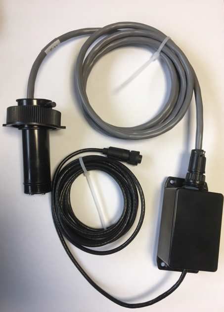
3.1 Packing list
The installation kit (ref : 90-60-016) includes :
- the sensor is equipped with a 2 meter cable and a waterproof connector.
- (réf 90-60-015)
- the interface box l’interface is equipped with a 4 meters cable and a waterproof connector
- (réf 90-60-172)
3.2 Specific tools required for the installation
The drilling of the hole for the through-hull is performed using a Ø 51mm crown saw drill bit
fitted with a guide pin.
3.3 Choice of the location
The choice for the location of the speedometer log sensor is crucial to achieve optimal
performances. Turbulences caused by the water flow under the boat can significantly disrupt
the operation of the speedometer.
The sensor must be :
- as vertical as possible, not more than 10° off the vertical,
- as close as possible to the axis of the boat,
- sufficiently far from the keel,
- always immersed, no matter what the heel,
- away from any source of electrical disturbance,
- accessible so it can be cleaned from the inside of the boat.
It is imperative that the water streams get to the sensor unperturbed.
On a sailing boat : the ideal position of the sensor is in front of the keel, along the axis of the
boat.
sensor
L
Position : 1/3 de L
Figure 2 : recommended location
- 7- 00_Loch_Electromagnetique_um_UK_17_REV2On a motorboat : the sensor must be approximately 50 cm back from the squat limit. It may be
necessary to prepare a 10 to 15 mm streamlined plate so that the vaned rotor is located beyond
the turbulent water layers.
Figure 3
- 8- 00_Loch_Electromagnetique_um_UK_17_REV23.4 Installation of the through-hull
- The sensor must install on Log through-hull kit, (réf : 31-35-001)
Once the location of the sensor is determined, follow the procedure below :
- From the inside of the boat, drill the pre-drilling hole, then from the outside, drill a 51 mm
diameter hole using the crown saw.
- Degrease the hull.
- Coat the flange of the through-hull with sealing paste. Place the through-hull in position.
- Inside the boat, lay some sealing paste around the through-hull.
- Position the though-hull by orienting the arrow towards the bow of the boat (see figure 4).
Similarly, on the outside of the through-hull, an arrow indicates the orientation : position this
arrow towards the bow of the boat.
- Screw the nut and tighten moderately.
- Grease the stopper and screw it onto the through-hull.
- Leave to dry for over 12 hours.
Caution : to guarantee the accuracy of the sensor, theSENSOR
axis (arrow) of
the through-hull of the speedometer log must imperatively be parallel to
the lubber line of the boat. A dissymmetry of the speed measurement
would cause a significant error on the true wind calculation.
Nut sensor
Trough hull axle Through-hull
Boat axle Safety wire
Through-hull nut
Sealing paste
Hull
Figure 4
Sealing paste
Note : a flat joint is delivered with the through-hull, to ensure the watertightness between the
hull and the through-hull. However, mounting this joint is not compulsory. For a more reliable
watertightness with time, we recommend you use sealing paste only.
- 9- 00_Loch_Electromagnetique_um_UK_17_REV23.5 Installation of the speedometer log
3.5.1 Installation precaution
The sensor must be positioned precisely:
- The axis of the sensor, passing through the positioning arrow, must be parallel to the boat's
heading line see figure below.
- The arrow must point forward.
Caution : The speedometer positioning arrow must imperatively point forward.
The sensor axis should be parallel to the boat's heading line.
Trough hull axle
Boat axle
Figure 5
3.5.2 Assembly Procedure
- Grease the two O-rings of the sensor with the silicon lubricant.
- Introduce the sensor in the through-hull.
- Gently screw the sensor nut until you feel a slight resistance.
- Then rotate the body of the sensor to position the fool proofing notch as shown in figure 5.
- Manually tighten the nut, to the thread root.
Antifouling : the immersed surfaces of the speedometer log sensor will rapidly become covered
with algae and seashells. Protect the through-hull with a thin coat of antifouling.
CAUTION :
- Do not introduce the sensor in the through-hull without lubrication, as it may damage the
seals.
- The paint and antifouling do not clog the electrodes.
- 10 - 00_Loch_Electromagnetique_um_UK_17_REV23.6 Electrical connection
The sensor is equipped with a 2 meter cable and a moulded waterproof connector. You will
connect the speedometer log sensor onto the interface box and then to the connector socket
marked speed sensor of the depth-finder log interface housing.
CAUTION :
- To guarantee the watertightness of the connectors, make sure they are properly screwed
onto their connector socket.
- The connection of the sensor must be performed with the installation power switched off.
4 MAINTENANCE
4.1 Recommendations
- The sensor is coated with silicon grease. It is however recommended to lubricate it
regularly (silicone grease only) in order to avoid locking in the through-hull.
- During boat lifting operation, remove the speedometer sensor from the through-hull and
place a stopper : the lifting straps could damage the speedometer sensor.
- The immersed surfaces of the sensor will rapidly become covered with algae and seashells.
Periodically clean the immersed surface of the sensor. If you do not use your instruments for
a long period of time, remove the sensor from the through-hull and place a stopper.
4.2 At port, how to remove a sensor from the through-hull ?
To perform maintenance and cleaning operations, it is necessary to remove the sensor from the
through-hull, when the boat is afloat. The sensor must be retrieved, then the hole of the
through-hull must be rapidly blocked with the stopper. This operation may seem difficult,
because water comes into the boat. However, with a bit of method and organisation, it can be
performed easily. Only a few decilitres of water will come inside the boat.
Procedure :
1. Clear the area around the sensor.
2. Lubricate the stopper and keep it within your reach.
3. Unscrew the sensor nut entirely.
4. Progressively retrieve the sensor, and be ready to block the through-hull with the stopper.
5. As soon as the sensor is removed, block the hole of the through-hull with the stopper, and
screw.
6. Only a few decilitres of water will come inside the boat.
Please note :
- The through-hull of the speedometer log sensor is fitted with a valve. The latter is not
waterproof but restricts the water ingress before the stopper is in place.
- 11 - 00_Loch_Electromagnetique_um_UK_17_REV2You can also read