Single Decontamination Shower - Product Manual - MFC International
←
→
Page content transcription
If your browser does not render page correctly, please read the page content below
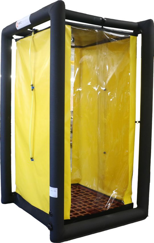
Single Decontamination Shower
                   Product Manual
Index
Technical Data / Capacity Parts 3
Parts List 4
Operational Instructions 6
Packing 8
Storage 9
Maintenance & Test Procedures 10
Repairs 11
WARNING: Carefully read this manual before operating the
Single Decontamination Unit.
NOTICE: The manufacturer takes no responsibility for the
consequences of actions not complying with the instructions
given in this manual.
2 © MFC International 2018Technical Data Product Code DS0022 DS0023 Length (cm) 143 143 Int. Length (cm) 110 110 Width (cm) 156 156 Int. Width (cm) 123 123 Height (cm) 250 250 Int. Height (cm) 215 215 Working Pressure (bar) 0.55 0.55 No. of chambers 1 1 Air Requirements (ltr) 400 400 Max. Water Inlet Pressure (bar) 3 3 Recommened pump flow-capacity (ltrs) 10/minute per nozzle 10/minute per nozzle Pack size (cm) 70x45x30 70x45x30 Weight (kg) 25 25 Number of Shower Nozzles 5 5 Number of Shower Hose Connectors 1 1 Number of Shower Brush Connectors 1 1 Number of Tubing Sleeves 2 2 Glove No Yes Window No Yes © MFC International 2018 3
Parts List
   This drawing and the copyright and design
therein are the property of mfc survival ltd.,
and neither the drawing or design or any
substantial part thereof may be reproduced
without prior written permission.

                                                                              10                                    2
                                                    6

                                                                                          www.mfcsurvival.com

                                                                     9

                                                                     3

                                                                                                                                             2503
                                                                                                                                      2152
            4                                                        4

                                                                                                                        D ECON UNIT

                                                                     5                                                                       11

                                                   FRONT                           SIDE
                                 12
                                                                         12                                     7                            8
                                                   1432
                                                   1100
                                                    EXIT

                                                            12

                                                                 9
      1560
      1230

                                                                 1

                                                                 5

                                                 ENTRANCE
                                                   TOP

            4                                                                      © MFC International 2018
Item Description
1 Inflatable Frame Neoprene Coated Polyester - Black
2 Shower Tent PVC Coated Polyester, Yellow
Top & Sump – PVC Coated Polyester, Black
Entrance/Exit – Clear PVC sheet
3 Observation Window Clear PVC Sheet
(DS0023 Only)
4 Sleeve with Glove Clear PVC Sleeve with PVC Glove
(DS0023 Only)
5 Drain Hose Sleeve PVC Coated Polyester - Yellow
6 Brush Hose Connector Plated Brass Push Fit Connector
7 Inflate/Deflate Valve D7 Black Acetal
8 Relief Valve A6 Black Acetal
9 Shower Hose PVC Hose c/w Plastic Fittings, Brass Nozzles
10 Logo Label Label with MFC Logo
11 Data Label Label with Product Data
12 Plastic Pallet Grating Top Surface - 120x100x15cm
13 Valise (not shown) PVC Coated Nylon - Orange
14 Repair Kit (not shown) Tube of Neoprene Adhesive and Repair Patches
© MFC International 2018 5Operational Instructions
1. DEPLOYMENT AND USE
1.1. At deployment point, select best site, particularly if a long term use is
anticipated.
The surface should be reasonably flat and level, free from stones, sharp objects
or holes in the ground.
The surface must be free from oil or chemical spills.
If required, position a groundsheet (optional) under the shower unit before
inflation to prevent damage to the sump.
1.2. Unpack the decon unit from its valise, and unroll it.
1.3. PREPARE FOR INFLATION:-
1.3.1 Remove dust cap from inflate/deflate valve, ensure the central valve diaphragm
is closed; i.e. the internal spindle is raised (push and turn to release).
The other valve positioned above it is the “Pressure relief valve”.
1.4. CYLINDER INFLATION
1.4.1 Fix Regulator to cylinder and connect delivery hose to Regulator.
1.4.2 Connect delivery hose to inflate/deflate valve, Hold delivery hose tight into
inflation valve and inflate until relief valve activates. Close cylinder valve. Do not
release hose during inflation. Failure to do this may result in personal injury.
1.4.3 Ensure dust cap is replaced to prevent ingress of dirt and water into the valve.
1.5. BELLOWS/PUMP INFLATION
1.5.1 Remove dust cap from inflate/deflate valve, ensure the central valve diaphragm
is closed, i.e. the internal spindle is raised (push and turn to release).
1.5.2 Attach bellows/pump hose to inflate/deflate valve.
1.5.3 Operate bellows/pump until relief valve activates.
1.5.4 Remove hose and replace dust cap on inflate/deflate valve.
1.6.
Guy ropes are attached to each frame upright so that it can be firmly anchored
to the ground using spikes. The guy ropes can alternatively be secured to strong
points such as trees or vehicles.
6 © MFC International 20182. SHOWER TENT
The shower tent is fitted with a clear overlapping flap entrance/exit at both ends.
The bottom of the flaps should be kept inside the integral sump to prevent
escape of contaminated water.
WARNING: To prevent possible injury from tripping, care should be taken
when stepping into and out of each section of the shower tent.
The shower tent may be removed from the inflatable frame and replaced if
required (Please contact MFC for further information).
2.1. A plastic pallet (120 x 100 x 15cm) should be placed in sump area to raise the
user above the level of the waste water. The pallet should have a grating top
surface to allow the water to drain into the integral sump.
2.2. SHOWER HOSE
The shower hose runs up the side of the tent, across the top and down the
opposite side, and is fitted with 5 shower nozzles (two on each side and one in
the top). The hose fittings are clamped through the tent. The water supply hose
is connected to the shower hose with the Geeka connector fitted in the end of
the hose. A cleaning brush on a hose may be connected into the push fitting in
the top corner, if required.
2.3. WASTE WATER
Waste water can be pumped from the sump by passing the hose through the
sleeve.
© MFC International 2018 7Packing
1. After every use, disconnect water supply hose, drain water from base of shower
and reservoir and allow to dry out.
2. Deflate the Shower unit. This is achieved by depressing the central spindle in the
inflate/deflate valve, (push and turn to lock open).
3. Before commencement of the folding operation, ensure that as much air as
possible has been evacuated from the frame.
NOTE: To prevent possible damage, do not walk on the deflating shower unit
to expel the air.
4. Lay the deflated Shower unit so the shower roof is positioned directly over the
floor, and the sides of the shower are tucked in between.
5. From left side, fold approx one third over, on top of the main frame.
6. Fold the other side over on top of the first (Use carrying valise for guide to pack
width).
7. Flat roll from the end (no valve) towards the inflate/deflate valve, expelling the air.
8. Lay the valise on the ground as an ‘open box’ and place Shower Unit into valise.
9. Fold up the ends of the valise and secure the webbing straps. Complete the
packing procedure by folding up the two remaining sides of the valise and
secure the webbing straps.
8 © MFC International 2018Storage
On return to base:
1. The shower unit should be packed (in valise) off the ground in a cool, dry
location away from direct sunlight and heat sources such as hot pipes or stoves.
Temperate Range for Storage: +5℃ to +40℃.
2. When the shower unit is completely dry:
a) proceed with cleaning instructions (see cleaning procedures located
on page 10).
b) it should be checked for wear or damage. If none is found it should
be repacked in the valise.
If any damage is found it should be repaired immediately in accordance with
the repair instructions (see repair instructions located on page 11).
Please contact MFC for further information on repairs.
© MFC International 2018 9Maintenance & Test Procedures
1. GENERAL
It should be noted that, due to the type of fabrics used in its construction, when
the Shower unit is wet, there may sometimes be visual evidence of miniscule
white bubbles, which form a line of froth at the seams and joints of the unit.
This is recognised within the industry as ‘lateral leakage’, and is simply air that
is trapped in the layer of nylon between the rubber coatings, forcing its way
to the nearest available edge of the fabric. This type of leakage will not affect
the performance of any inflatable product over the course of an operational
procedure, and can be safely ignored.
However, if there is evidence of large, transparent bubbles, this is clearly
evidence of a leak that must be repaired at the earliest convenience (Please
contact MFC for further information).
The following is a recommended regime for maintenance & test.
1.1. CLEANING
This should be carried out using soap and water.
WARNING: To prevent possible damage. Do not use strong detergents,
bleach or any type of hydrocarbons.
If the shower tent or partitions become excessively contaminated, and cannot
easily be decontaminated, they should be removed and incinerated.
A replacement shower tent or partition can be sourced from the manufacturer
(Please contact MFC for further information).
1.2. SHOWER FITTINGS AND HOSES
The holes in the shower heads may become partially blocked with sediment
over a period of time. This may be rectified by cleaning the parts with soap and
water, thoroughly dry the parts before reassembly. Ensure any sealing washers
are refitted. Check hoses and fittings for leaks and repair / replace as necessary
(Please contact MFC for further information).
WARNING: To prevent possible damage. Do not use strong detergents,
bleach or any type of hydrocarbons.
2. QUARTERLY
2.1. Check control equipment as per relevant manual.
2.2. Inflate Shower unit to working pressure.
10 © MFC International 20182.3. Check audible relief valve operation.
2.4. Whilst inflation system is charged, check connections and valves using
brush and soapy water.
2.5. When relief valve has operated, and the unit is at working pressure; it can
be left to stand for a length of time that would be comparable to an operational
situation (e.g. 6 to 8 hours).
2.6. After this time, the Shower unit should still be firm.
2.7. If the Shower unit has become soft, the air-loss should be located by
applying a soapy-water solution.
2.8. Any significant leaks (See 1 above) should be marked and repaired
using the repair kit provided.
2.9. Check shower hoses and fittings for leaks and repair / replace as necessary
(Please contact MFC for further information).
3. RECOMMENDATIONS
3.1. Shower units should undergo an annual test carried out by the manufacturer,
or persons certified by the manufacturer. If in doubt please contact the MFC
service department on +44 (0)1443 433075.
Repairs
As a general rule, punctures and other damage will need to be assessed in two
categories:
a) that which is repairable at the base, or b) serious damage that will need to be repaired
by MFC International Ltd.
a) Repairs that are manageable at the base workshops will be minor punctures
to any area of the Decon Shower. These can normally be repaired by the
application of a small repair patch (provided in the repair kit).
b) Repairs that should be carried out by MFC will be the more serious kind, such
as damaged valves, badly torn fabric (either on the sidewalls or the flat
surfaces) and the replacement of damaged fittings. Please contact MFC for
further information.
© MFC International 2018 11MFC International Naval Yard Tonypandy Rhondda Cynon Taff CF40 1JS T. +44 (0) 1443 433 075 F. +44 (0) 1443 420 448 sales@mfc-international.com www.mfc-international.com A Respirex International Limited Group Company SA-MA68-02
You can also read