Field Setup Guide 2018-2019 FIRST Tech Challenge - Rev 1.1
←
→
Page content transcription
If your browser does not render page correctly, please read the page content below
Rev 1.1

             2018-2019 FIRST® Tech Challenge
                      Field Setup Guide
AndyMark Field Layout and Finishing Guide for 2018-2019 FIRST® Tech Challenge

                                    1
This guide contains instructions for setting up the Field Elements for the
                      2018-2019 FIRST® Tech Challenge Game

                 ROVER RUCKUSSM Presented by Qualcomm® Incorporated

         Read through all the instructions and take a parts inventory
         before you begin to assemble and setup the game elements!

REVISION HISTORY
Rev.                     Date      Description
1.0                      8/29/18   Initial Release
1.1                      9/7/18    Updates and additions for clarity

TOOLS NEEDED
Component                             QTY                              Part Photo

       Safety Equipment            As Needed

        Safety Glasses                  1

         Utility Knife                  1

             File                       1

           Scissors                     1

       Diagonal Cutters                 1

        Tape Measure                    1

         Color Printer                  1

                                                  2
FULL FIELD REQUIREMENTS
    Component                      Part #                     QTY              Part Photo

 FIRST Tech Challenge
                                 am-0481a                       1
    Field Perimeter

  5/8” Gray Soft Tiles          am-2499-36                      36

Competition Field Components

     Component                     Part #                      QTY             Part Photo

                          See Field Assembly Guide
        Lander                                                  1
                          for assembly instructions.

                          See Field Assembly Guide
   Crater Segments                                              20
                          for assembly instructions.

      11” Cable Tie
    (extras included,                                            22
   additional will be             am-1067              needed each time the
   needed for future                                   craters are assembled
         setups)

      Lower Clip                  am-3875                       4

 Gold Scoring Mineral             ftc-2013                      90

 Silver Scoring Mineral           am-2850                       60

                                                       3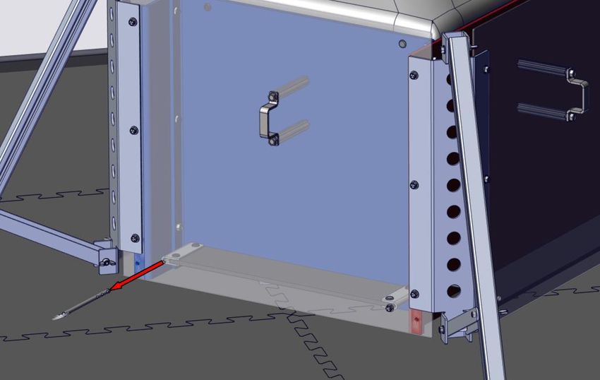
2” “Red” Gaffers Tape           am-2946               as needed

   2” “Electric Blue”
                                am-2947               as needed
     Gaffers Tape

    Cardstock for
  Navigation Target
                                                         8
  (Printed from FIRST
   Resource Library)

Command Mini Hooks
   P/N: 17006-VP
                             P/N: 17006-VP
                                                         8
For use with AndyMark,
   IFI and Logo Loc
       Perimeters

    Velcro® Dots

                         Roughly ¾” diameter or
  For use with early                                   1 pack
                                 larger
generation AndyMark
     Perimeters

Clear Page Protection       Similar to Staples
                                                         4
       Sleeves                 P/N 40713

                                                  4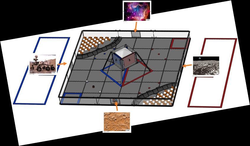
Match Timer Components
   Component                    Detail                     QTY           Part Photo

                          Running Java 1.7 or
  Laptop/Netbook                                        1 per field
                                higher

                        Roughly a 17” monitor or
Field Display Monitor                                   1 per field
                                bigger

                            For Laptops and
       Power                                           1 set per field
                                Monitors

                        For connecting Monitors
    Video Cables                                           1 set
                               to laptop

Computer Speakers       For match sound effects        1 set per field

                                                   5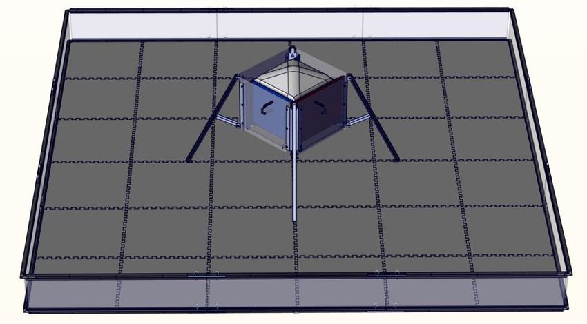
Part 1: Setting up the Floor and Field Perimeter
Step 1-1: Lay the tiles with the smooth surface              Step 1-2: Critical Mandatory Step: Trim all outer
facing up in a 6x6 grid pattern.                             tabs from the 20 Soft Tiles on the outside edges of
                                                             the field.

 NOTE: Lay the tiles out and mark the outer edge to
 be cut. Use a sharp utility knife and a straight edge
 or a band saw (if available) to get a smooth clean
 edge.

Step 1-3: Note that there are several FIRST Tech Challenge Perimeter wall designs. The wall designs fall
into two categories. The smooth/non-cavity sides should face towards the inside of the Playing Field as shown in
the illustration.

 Perimeter                   Wall Design Categories                                     Wall Height
 AndyMark (current)          Smooth on one side and an open cavity on the other         12.125”
                             side
 IFI Perimeter               Smooth on one side and an open cavity on the other         11.5”
                             side
 Logo Loc Perimeter          Symmetrical inside and outside surfaces                    12.375”

  NOTE: If using the AndyMark Field Perimeter, ensure that straps are installed to keep walls in place during game
                                                       play.

                                                         6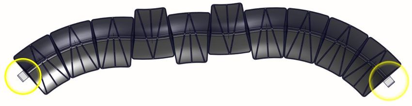
Part 2: General Layout and Orientation
                               MATCH TIMER
                               DISPLAY TABLE

                                                                            RED ALLIANCE
   ALLIANCE
     BLUE

                                  AUDIENCE

    NOTE: The Match Timer Display table should include the timer screen as
 described in section 10. This should be placed to ensure that the Teams are able
     to see the clock and hear the timer sounds for each period of the Match.
                                       7
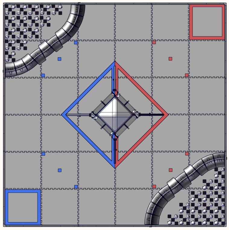
Part 3: Lander Placement
ROVER RUCKUSSM Presented by Qualcomm® Incorporated is played with one Lander diagonally placed in the center
of the field. Build instructions can be found in the Field Assembly Guide. The BLUE side of the Lander should be
placed facing the BLUE Alliance Station. The RED side of the Lander should be placed facing the RED Alliance Station
From the audience view, the RED should be placed on the right and the BLUE on the left.

                                    BLU                                   RED
                                     E

                                                 AUDIENCE
 Step 3-1: The feet of the Lander should line up with the two center seams of the SoftTiles. When placed on the
 field, the Lander should be centered and the feet should be evenly spaced out from the center point. The anchor
 should measure 59.4” from the center of the field to the bolt on the anchor.

 Step 3-2: Use the Under Tile Disk with elevator bolt           Step 3-3: The SoftTiles should sit flat on each
 and ¼-20 Nut to anchor it into place. The SoftTiles            intersection of the leg.
 should sit between the disk and the foot.

                                                        8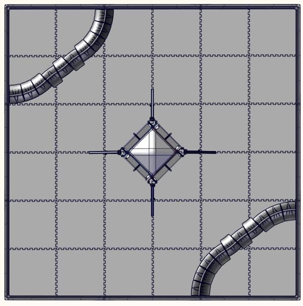
Step 3-4: During match play, teams will fill the sides of the Lander with Gold and Silver scoring elements. During
the field reset period between matches, the pins located on each side of the lander can be removed to allow the
scoring elements to fall out the bottom.

Step 3-5: For match play, ensure the pin is fully inserted through the floor of each side of the lander.

                                                       9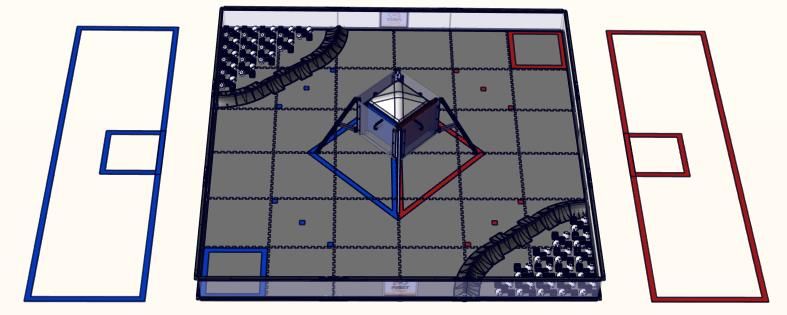
Part 4: Crater Assembly and Placement
ROVER RUCKUSSM is played with two Craters on opposing corners of the field. From the Audience perspective a
Crater should sit in the upper left corner and a Crater should sit in the lower right corner. Each Crater Section is the
same and assembly instructions are as shown below.

                                                   AUDIENCE
 Step 4-1: Each Crater is made up of 10 Crater Segments. When counting from left to right, the 5th and 7th
 segments have their long side pointed outwards. The remaining segments have their long sides facing inwards.

 Step 4-2: To create a Crater, turn each segment upside down and place together. Use a cable tie to loop
 horizontally through the holes in each section to hold together. Tighten the cable tie down all the way so the
 sections don’t separate. When flipped right side up, the Crater Segments should sit flat on the SoftTiles and not
 have any spaces between the bottom edges. Trim the ends of the cable tie.

                                                         10
Step 4-3: Attach the 10 segments together. On both ends of the Crater, place a Lower Clip.
Step 4-4: The holes on the Lower Clip should line up Step 4-5: Secure the clip to the Crater Section with a
with the holes in the Crater Segment. The clip should cable tie.
point up towards the top of the Crater.
Step 4-6: Place each Crater into the corner of the field Step 4-7: The clip will sit underneath the field
perimeter. From the Audience perspective a Crater perimeter rail and secure the Crater to the
should sit in the upper left corner and a Crater should sit perimeter.
in the lower right corner. The end Crater Segments
should sit up against the field perimeter and there
should be no gaps between the bottoms of the Crater
Segments.
11Part 5: Game Piece Placement
Step 5-1: ROVER RUCKUSSM is played with two types of scoring elements, Gold and Silver. Prior to the start of each
match, two Silver Minerals and one Gold Mineral are placed onto the Sample Fields. The order should be Silver, Gold,
Silver. The Gold Minerals should be placed “waffle side” up.
AUDIENCE
Step 5-2: Prior to the start of each match field personnel will place approximately half of the fifty two (52) Silver and
half of the eighty six (86) Gold Minerals into each of the Craters. The Silver and Gold will be randomly mixed.
12Part 6: Navigation Target Placement
Step 6-1: Download Target Images found on the Step 6-2: Print the navigation targets in color, not
FIRST Tech Challenge Game and Season Info Page: greyscale on 8.5x11” White Cardstock. The Print
http://www.firstinspires.org/resource- resolution must be at least 300DPI. The targets can
library/ftc/game-and-season-info be laminated or placed in sheet protectors.
Step 6-3: Print the FIRST Tech Challenge Logo in Step 6-4: Insert both images (target and logo) into
Landscape Orientation on 8.5x11” White Cardstock. the sheet protector sleeves. For AndyMark, IFI and
The logo should be centered and cover the nearly LogoLoc perimeters, targets can be hung in place
the entire page. This image should be on the reverse with Command Adhesive Mini Hooks. For early
of the target image. generation AndyMark Perimeters, use Velcro Dots to
http://www.firstinspires.org/resource- hang the targets.
library/ftc/game-and-season-info
Step 6-5: The navigation target should be placed on the center perimeter panel as measured from the metal
perimeter border and not the polycarbonate. The bottom of the image measures 5.75 inches from the tile floor to
the center of the navigation target image. The target image centerline is marked by a black line on the outside of
the image.
13Step 6-6: The navigation target should be placed around the field perimeter as shown below.
14Part 7: Tape Lines
Step 7-1: Use 2” RED and BLUE Gaffers Tape to mark a one-tile Depot. The BLUE Depot is located in the corner
without a Crater closest towards the BLUE side of the Lander. The RED Depot is located in the opposite corner. The
tape line should sit inside of the SoftTile seam and along the field perimeter as shown.
Step 7-2: Use 2” RED and BLUE Gaffers Tape to mark the Landing Zone under the Lander. From the Audience
perspective, the RED Landing Zone is located on the right side. Tape a vertical line under the Lander extending from
the near Lander Leg to the far Lander Leg. RED and BLUE tape should be placed side by side along the SoftTile seam.
Tape a square around the outside of the Lander Legs. RED tape should be used adjacent to the RED faces of the
Lander and BLUE tape should be used adjacent to the BLUE sides of the Lander as shown below.
AUDIENCE
15Step 7-3: Use 2” RED and BLUE Gaffers Tape to mark the scoring element starting locations. Three 2”x2” tape squares
should be placed on the tiles between the corners or Crater as shown below. The two outer tape marks should align
with the inside of the SoftTile seam. The third tape mark should be located in the center of the tile. If you were to
draw an imaginary line through the three squares, that line would be parallel to the front faces of the lander. Each
square should measure 14.5” from corner to corner as shown below.
Step 7-4: Taping the Alliance Stations:
Use 2” RED and BLUE Gaffers Tape to mark the edges of the Alliance Stations on the floor outside the playing field as
shown below. The RED alliance station should be on the right side when viewed from the audience. The BLUE alliance
station should be on the left side when viewed from the audience.
Each alliance station is a 42” x 144” rectangle measured from the outside of the tape. The front edge of the Alliance
Station should be approximately 18” away from the field perimeter. The sides of the Alliance Station box should line
up with the front and back edges of the field perimeter.
In the center on the front edge of each alliance station, a 2’x2’ Scoring Referee Station should be taped off as well.
AUDIENCE
16Step 7-5: Referee Question Box
The Referee Question Box is a place where Teams can ask questions of the Referees after a
Match.
The Referee Question Box must be placed in the Competition Area in a location where it
will not interfere with the current running Matches, but close enough that the Referees will
be able to see a student waiting at the Question Box. The Question Box can be as simple
as a 3ft Gaffers Tape square on the floor.
17Part 8: Match Timer Display
A Match Timer Display has been integrated into the Scoring System to be used as a visual and audible aid to Teams
on where they are in a Match. Even though the Match Timer Display is integrated into the Scoring System, the two
roles are independent of one another.
Equipment and Program Needed
• Laptop/Netbook
o Copy of the current Scoring System installed
• Field Display Monitor
• Power
o For Laptop
o For Monitor
• VGA or video cable
o To connect the laptop to the monitor
• Speakers
Scoring System Download and Installation
The Scoring System will require Java 1.7 or higher. The application can be downloaded from:
• www.java.com
The Scoring Software is available for download from:
• http://www.firstinspires.org/node/5146. To install the software, unzip the downloaded file into the folder
of your choice. FIRST suggests that users save the file to the computer’s desktop to easily access the
program. The software will be run from this directory.
After
downloading Once the
the software files have
from the been
website, you extracted, a
will need to new icon
unzip the file. should
Right click appear.
the zipped Double click
file, and this icon to
extract the
To run the
system, double
click the
“FTCScoring”
executable Jar
File. This will
open up the
main page of
the Scoring
18Step 8-1: To run the Match Timer Display, click on Step 8-2: In order to fit the Match Timer Display to
the “Match Timer Display” button from the main the monitor it will be projected onto, select the
Using the Software
Scoring system page. appropriate screen resolution.
Step 8-3: Next make sure “Control Shot Clock Here” Step 8-4: After clicking “OK”, the Match Timer
is selected, type in the name of the Event, and click Display will appear, along with the Match Timer
“OK”.
control box.
Using the Match Display Timer
The match timer display volunteer will work with the Game Announcer to start the clock as the Game Announcer
announces the “3-2-1-GO!” countdown that starts the autonomous period of the match. The volunteer will click the
“Start” button on the Match Timer control box to start the clock. A separate volunteer does not need to be recruited
for this position; this can be done by a Referee, Head Referee, Field Technical Advisor, or a Field Reset volunteer.
19Although the match timer display is a function of the scoring system, the volunteer running the match timer display
will not need to enter scores. They are only responsible for beginning the timer at the start of each match. The timer
will automatically switch from autonomous to the driver controlled period of the match.
20You can also read