NAVIGATOR II INSTALLATION MANUAL
←
→
Page content transcription
If your browser does not render page correctly, please read the page content below
Navigator II                       ™

  Installation MANUAL
For Static and Pan / Tilt Configurations

Document Number: 432-0001-00-12, rev 100

© FLIR Systems, Inc., 2008. All rights reserved worldwide. No parts of this manual, in whole or in part,
may be copied, photocopied, translated, or transmitted to any electronic medium or machine readable
form without the prior written permission of FLIR Systems, Inc.

Names and marks appearing on the products herein are either registered trademarks or
trademarks of FLIR Systems, Inc. and/or its subsidiaries. All other trademarks, trade names, or
company names referenced herein are used for identification only and are the property of their
respective owners.

This product is protected by patents, design patents, patents pending, or design patents pending.

The Navigator II imaging system is controlled by US export laws. There are special versions of this sys-
tem that are approved for international distribution and travel. Please contact FLIR Systems if you have
any questions.

FLIR Systems, Inc.
70 Castilian Drive
Goleta, CA 93117
Phone: +1.888.747.FLIR (+1.888.747.3547)
www.flir.com
PAN/TILT CONFIGURATION
Introduction
Your Navigator II comes with the camera head, a cable that goes from the camera head to the Joystick
Control Unit (JCU) and Monitor, the JCU and the mounting hardware described below.
Installation
Caution! The Navigator II should be installed by a factory-authorized installer. Incorrect installation could
void your warranty.
DO NOT separate the camera from its Pan/Tilt base during installation. Doing so will void
your warranty.
Camera Mounting
Caution! Mount your Navigator II with the pedestal sealed to a flat, horizontal surface with the camera
above the mounting plane. Any other type of installation is not appropriate, may result in damage to the
camera, and may void the warranty.
Step 1 Using the “Camera Mounting Template” supplied as a part of the Installation Manual as a guide,
drill the mounting holes and 1.25” through-hole for the cable seal. Before drilling holes, ensure that the
template is facing the right direction; mount the camera with the front of the base facing the intended
viewing direction.
Mount the camera with the front of the base towards the primary viewing direction. The camera will
rotate, pan, approximately 180° in either direction from the primary viewing direction.
Step 2 Feed the cables through the 1.25 inch hole. Check that all the screw holes line up and the
front of the camera base is towards the primary viewing direction. (The cables exit the rear of the
camera base.)
Step 3 Check the gasket under the base for integrity and using a 3mm Allen wrench, securely fasten
the camera in place with four M5 socket-head machine screws, flat washers, lock washers, and hex
nuts provided. See Figure 4
In order to secure the mounting screws, manually tilt the camera to its highest position and rotate the
body until the access hole in the front of the camera body is lined up with the mounting screw. Rotate
the camera to tighten each of the four mounting screws.
Your Navigator II can be installed with machine screws, washers, lock washers, and hex nuts as de-
scribed below, or it can be secured using wood screws. Both types of mounting hardware are sup-
plied.
Step 4 Securely attach the ground wire to the vessel ground plane.
Step 5 Route the control/power cable to the Joystick Control Unit and the video cable to the monitor.
See Figure 1 for a schematic representation of the cabling connections.
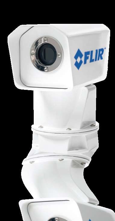
Figure 2

Figure 1

 Figure 3              Figure 4
(for Reference Only)
Joystick Control Unit Mounting
Caution! Changing the wiring configuration of the Navigator II or attempting to utilize controllers or
wiring harnesses other than those supplied by FLIR may cause permanent damage to the unit and may
void the warranty.
Caution! Do not connect the camera to anything other than 12 VDC power. Operating the camera
outside of the specified input voltage range or the specified operating temperature range can cause
permanent damage.
Caution! Ensure that power is turned off at your main electrical panel before wiring the power to your
Navigator II Joystick Control Unit.
When routing the camera cables to the desired location for the display and the Joystick Control Unit,
verify that the cables will reach before cutting and drilling mounting holes.
Note: Use Belden 1189A or equivalent 75 Ohm RG59/U cable to extend the video cable provided up to
a 100 foot total length. To extend the power and communication cable use Belden 1502SB or equivalent
20 AWG two twisted pair (four conductor), 7/28 stranded cable. See http://bwccat.belden.com/.
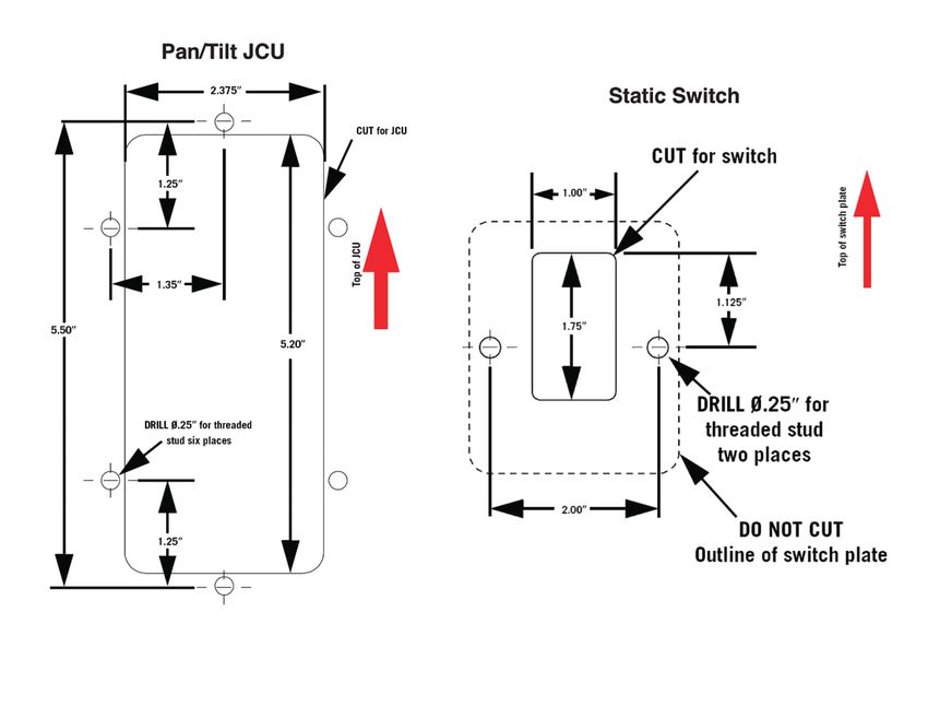
Step 1 Using the “Joystick Control Unit Mounting Template” supplied as a part of the Installation Manual
as a guide, drill holes for the six studs and cut an access hole for mounting the Joystick Control Unit.
Step 2 Connect the control cable to the un-capped connector on the back of the JCU (that’s the
connector that’s not directly under the joystick). The capped connector (the one that is directly
under the joystick) is only used if you plan to install a second control station. To install a second control
station, run the cable supplied with the Dual Control Station kit from the capped connector of the
primary controller to the uncapped connector of the secondary controller and connect both securely.
Step 3 Check the gasket under the Joystick Control Unit for integrity and securely fasten the switch in
place with the two M4 flat washers, lock washers, and hex nuts provided.
Step 4 Attach the ground wire securely to the vessel ground plane.
Step 5 Connect the 12 VDC power and return wires from your protected main electrical panel to the
JCU wiring harness. Wire must be 16-gauge with a maximum run of 100 feet.
Figure 5
Uncapped Capped
Connector Connector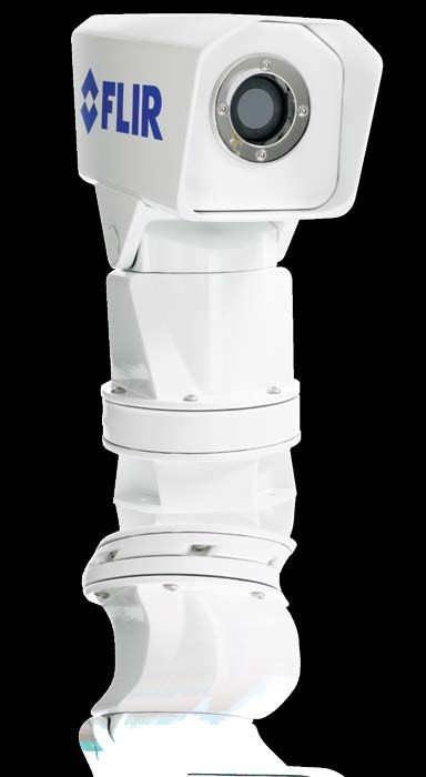
Figure 6
(for Reference Only)

STATIC CONFIGURATION
Thank you for buying your new Navigator II! If you need help during the
installation process, call 888.747.3547 to speak with one of
FLIR’s Applications experts.
A qualified marine electronics technician should install your Navigator II,
as incorrect installation could void your warranty.
Introduction
Your static Navigator II comes with these standard components:
   • Camera head
  • 25’ system cable that goes from the camera head to the
		 On/Off switch and customer-supplied Monitor
   • 25’ video cable
   • On/Off switch
  • Mounting hardware (machine screws, washers, lock washers,
		 and hex nuts)
You may need to supply:
  • 16-gauge electrical wire from the vessel’s power control panel
		 to the Navigator II’s On/Off switch; maximum run of 100’
   • Miscellaneous electrical hardware and connectors
   • Camera base mount or shims (see below)
Before you begin:                                                       Figure 7
   •   Find a good place to mount the Navigator II
		 o      Mount the Navigator II as high as practical, but without interfering with any radar, navigational
			       or communications electronics, and minimizing the degree to which vessel structures block
			       the camera’s view
		 o      Mount the Navigator II as close to the vessel’s centerline as possible so you will have a
			       symmetrical view of on-coming traffic
		 o      Navigator II should be mounted on a flat surface with the base on the bottom and the camera
			       on top. Do not hang the Navigator II upside down; your picture will display upside down, and
			       you may damage the Navigator II
   • Think about where the Navigator II will be pointed
		 o      Mount the Navigator II with a slight downward angle, so the tip of the bow is visible in the lower
			       quarter of the image, and the path of the vessel is clearly visible, even at high deck angles
  •    If your boat does not have a structure with angles to permit this alignment, you may have
		     to supply shims. These are available from PYI Inc., at www.pyiinc.com. PYI’s Seaview line
		     includes a 4° wedge (the FW-4-1), and an adjustable 0°-12° wedge (the AMA-W) that can be
		     used to fine-tune your Navigator II’s tilt angle during installation.

Before you drill holes:
  • Once you have selected your mounting location, verify that you will have access to both sides of
    the mounting hardware
		 o      While FLIR provides wood screws, we STRONGLY recommend using the machine screws,
			       washers and lock nut. To do so will require you (and possibly an assistant) to have access to
			       both sides of the mounting hardware
  •   Note also whether you will have to remove any interior trim panels to gain access to the mounting
		    hardware, and remove them ahead of time. Take extra care to ensure that your Navigator II is
		    properly aligned to give you an optimal image. It should be pointed straight ahead and at a slightly
		    downward angle to account for the planing angle of your boat – just enough so that you can see
		    the bow of your vessel.

                                              Figure 8
                                             (for Reference Only)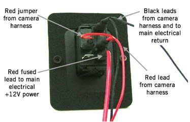
Camera Mounting – STATIC CONFIGURATION
Once you have confirmed that the selected mounting location will provide an unobstructed view and a
properly framed image, use our template, or the one from PYI, to determine where you will drill your
mounting holes.
Step 1 Using the “Camera Mounting Template” supplied as a part
of the Installation Packet (or the one supplied with the PYI shim,
should you need to use one) as a guide, mark the locations of the
holes you will drill. Before drilling holes, ensure that the template’s
front arrow lines up with the direction you have already determined
for the Navigator II. Drill the mounting holes and the 1.25” through-
hole for the cable seal.
Step 2 Disconnect the terminal lugs from the On/Off switch. The
red wire with the in-line fuse will be separate from the rest of the
harness and may stay attached to the switch.
Step 3 Feed the cable and the cable seal through the 1.25 inch hole.
Step 4 Check that all the screw holes line up and the camera is facing the intended direction. Make sure
that the gasket under the base is in place and undamaged, and, using a 3mm Allen wrench, securely
fasten the camera in place with four M5 socket-head machine screws, flat washers, lock washers, and
hex nuts provided.
Step 5 Securely attach the ground wire to the vessel ground plane.
Step 6 Route the cable to the On/Off switch and the monitor. See for a schematic representation of
the cabling connections.
If at all possible, DO NOT separate the Camera from its base during installation. If you are using the
supplied wood screws to mount the Camera base to the mounting surface, and you find that you do not
have enough clearance to access the screws with your screwdriver, you should be able to loosen the
screws that hold the Camera head to the base enough to provide ample room.

                                                 Figure 9
Fuse and On/Off Switch Mounting – STATIC CONFIGURATION
Caution! Changing the wiring configuration of the Navigator II or attempting to utilize controllers or
wiring harnesses other than those supplied by FLIR may cause permanent damage to the unit and may
void the warranty.
Caution! Do not connect the camera to anything other than 12VDC power. Operating the camera
outside of the specified input voltage range or the specified operating temperature range can cause
permanent damage.
Caution! Ensure that power is turned off at your main electrical panel before wiring the power to your
Navigator II camera On/Off switch,
After routing the camera cables to the desired location for the
display and the ON/OFF switch, verify that the cables will reach
before cutting and drilling mounting holes.
Step 1 Using the “Switch Mounting Template” supplied as a part
of the Installation Packet as a guide, drill holes for the switch studs
and cut the access hole for mounting the On/Off switch.
Step 2 Connect the 12VDC power and return wires from your
protected main electrical panel to the camera system wiring
harness. Wire must be 16 gauge with a maximum run of 100
feet. The power leads are the red and black wires without
terminal lugs.
Note: Depending on your switch mounting location you may want to connect the terminal lugs either
before or after installing the switch.
Step 3 Check the gasket under the switch plate for integrity and securely fasten the switch in place
with the two M4 flat washers, lock washers, and hex nuts provided.
Step 4 Connect the camera harness terminal lugs to the ON/OFF switch. As shown below, there are
five blade terminals in three horizontal rows. Only four of the terminals are used.
Figure 10 Figure 11
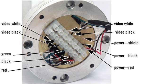
(for Reference Only) (for Reference Only)Disassembly and Assembly of the Camera Base – FOR STATIC CONFIGURATION ONLY If you are mounting the camera with wood screws, it may be necessary to partially or completely remove the base from the camera in order to securely attach the base to the vessel. With the camera removed, there is a screwdriver access hole for each mounting screw in the base flange. Remove the camera from its base as described in the following steps. Note: Removing the camera from its base for installation may require that you disconnect power wires from their terminal block and the video cable from its connector. Step 1 Using a 2.5mm hex wrench, remove the six M4 socket head screws attaching the camera to its base (only four screws are shown in Figure 12). Carefully separate the camera from its base. There is a small service loop between the camera and the base. Step 2 Disconnect the conductors at the cable side of the terminal block. Note the wire color code for reconnecting the wires to the terminal block. Figure 13 Step 3 With the camera removed from its base, using the self-tapping screws supplied, continue with the installation as described above. To reassemble the camera to the base, continue with the following steps. Step 4 Reconnect the four conductors and shield to the cable side of the terminal block. Note: To ensure a lasting seal, apply loctite 635 or equivalent to the M4 screws holding the camera to its base. Step 5 Reposition the camera on its base, ensuring that the front window is facing the correct direction. Step 6 Apply loctite to the six M4 button head screws and using a 2.5mm hex wrench, alternately tighten the screws to secure the camera in place.
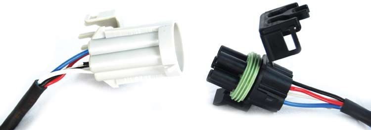
NAVIGATOR II SPLICE KIT – Applies to both configurations
For installations requiring the easy removal and re-installation of the Navigator II camera body, the
camera comes with a Splice Kit. The Splice Kit includes:

                                                                            5-way Weather Pack tower

            Shroud

   Weather Pack Strip Seals
      (color may vary)                                                        Male and Female terminals

Installation procedure:
Step 1 Determine the place you would like to install the Splice Kit.
Step 2 Trim off outer cable jacket exposing four insulated wires and the un-insulated signal drain.

Step 3 Strip approximately ¼” of insulation off each wire.

Step 4 Slide Strip Seal over each wire, so that the narrow end is flush with the end of the wire’s insulation.

Step 5 Crimp terminals to the wires and Strip Seal as shown.

                                                                         Crimp Here
Step 6 When finished, all 5 terminations should look like this (female termination shown). Note that the un-insulated signal drain is also terminated. Step 7 Insert the male terminations in the grey shrouds and the female terminations in the black towers. Push them in until you hear them click into place. (More detailed Weather Pack termination instructions are available on their website, http://www.weatherpack.com/weatherpackfaqs.html.) CAUTION!!! The shroud and tower are keyed to ensure one-way connection. Take care to make sure that the wires on each end match the other, or you will damage the Navigator II! Step 8 When you are sure that the wires will mate correctly, snap the tower and shroud together. Check for proper signal continuity before you apply power to the system.
The Splice Kit also includes Snap-N-Seal video connectors; their use is optional.

Step 1 Slide connector assembly over cable as shown.

Step 2 Prepare cable end. Cut the cable end off square before starting
the prep.

Step 3 If using single braid cables, fold the braid
over the jacket. Fold the inner braid over the jack-
et.

Step 4 Twist connector to remove from plastic
sleeve. (Plastic ring may stay attached between
connector collar and nut).Place connector over
cable end until cable dielectric is flush with end of
post. Push plastic sleeve into connector.

Step 5 Finish the connector to cable installation by
crimping with the appropriate finishing
You can also read