2018 Dayton Hamvention Drake Forum - WB4HFN
←
→
Page content transcription
If your browser does not render page correctly, please read the page content below
2018 Dayton Hamvention Drake Forum
• Drake Forum Committee

• Mark Gilger – WB0IQK
• Peter Shilton – VE7PS
• Ron Baker – WB4HFN
• Jeff Covelli – WA8SAJ
Agenda

          User Survey

     Rebuilding 4 line PTO’s

Recurring Technical Net Questions

   Question & Answer Session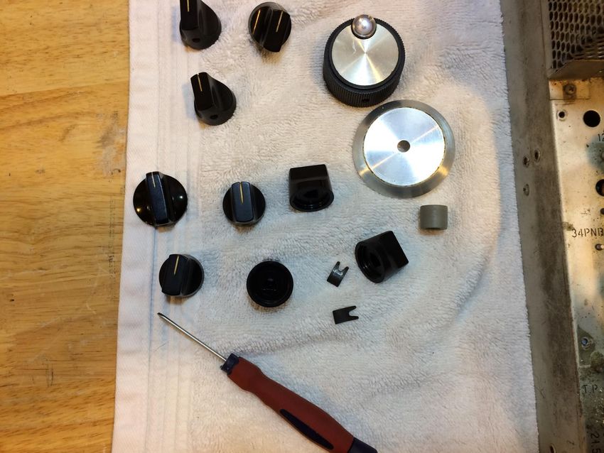
Drake Forum

           Request for information…

•   Suggestions for future Forum subjects.

•   Future Forum presenters needed.

•   Send information to WB0IQK@ARRL.NET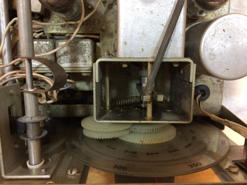
FORUM SURVEY

1 How many people
  attended last years 2017
  forum?
FORUM SURVEY

2. How many currently have a Drake radio?

3. How many plan on obtaining one?

4. How many operate their Drake Radio
    regularly?

5. How many don’t currently own one, but have
    in the past?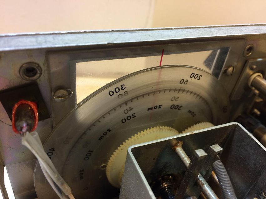
FORUM SURVEY

6. How many people still have their original
    Drake purchased back in the 60 - 80’s?

Note: There were 133 people attending the
   2017 forum.
K4OAH - GAREY BARRELL (SK 2018)
Drake Trivia

    The first Drake Dayton Forum
        was held in what year?
                      1998
• Started by: W8NS (Ex: WZ8O), Don Spillman
     & WA4SDE, Danny Shrader (SK 2017)

              • Number of years: 20

M.V.G.   May 2016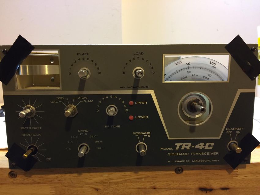
Drake Trivia

• What year was the Drake & Antique Tube
  Net started on 3.865mhz?

• It was started in 1994 by Danny Shrader,
  WA4SDE and Jeff Weinberg, W8CQ.
                  ( 23 years)
Drake Trivia
• The 40 meter Drake Technical Net was
started in what year?
• John Loughmiller, KB9AT and Jeff Covelli,
WA8SAJ started it in 1999.
( 19 years)Resources
Drake Technical Net: Sunday, 7238 kc @ 4:00 PM Eastern
Drake & Antique Tube Gear Net: Tue. 3865 +/- kc @ 8 pm
Eastern
Canceled due to a lack of participation
Drake West Coast Net : Thur. 3895 +/- QRM @ 8pm Pacific TimeResources
Drake Family Affair Book by John
Loughmiller, KB9AT,
Available @ Universal Radio
Drake Technical Information Exchange
567 page Compendium,
Web: http://wb0iqk.webs.com/
or
Email: WB0IQK@GMAIL.COMPREFACE • This presentation by Peter Shilton, VE7PS, was given at the Drake forum at Hamvention 2018. • Please read and study Neil, K1VY’s excellent article, “Drake PTO - Smooth and Silky” prior to working with this presentation. It is available on Ron’s website at www.wb4hfn.com. • Neil’s article features a mid-run C-line PTO with a “dual lever, all-plastic design”. I have featured an earlier “no lever, all plastic gear” design, though I do refer to the dual lever and the later one lever, all metal (well, almost all) gear design. • In my presentation, I have tried to include instruction on certain points that many have indicated to me they have trouble with, such as removing the front panel. Once you know what to expect, panel removal becomes a 5 minute job and is well worth the effort, even if you are not removing the PTO. • I can’t stress enough that you need to take a picture at every step of the PTO disassembly, as it would seem no two are ever quite the same.
RE-VISITING THE
DRAKE 4-LINE PTO’S
REMOVAL, CLEANING, AND RE-INSTALLATION.

PETER SHILTON, VE7PS
HAMVENTION 2018
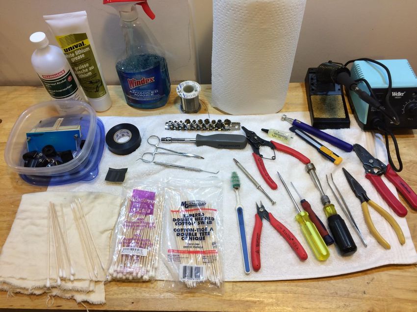
WHAT DO I BRING TO THE TABLE?
Q-tips, toothbrush, rags,
paper towels, vinyl tape,
600 grit emery.
Flat-bladed screwdrivers.
Dental pick, hemostat,
tweezers.
¼” and ½” Nutdrivers.
Pliers, small diagonal cutters.
Light oil, grease.
Solder, soldering gun.
OK – LET’S GET AT THE PTO!

• Remove the 12
 cabinet screws and
 both top and bottom
 cabinet sections.
• Remove the lamp
 bracket. Don’t lose
 the 2 screws or 2
 standoffs!
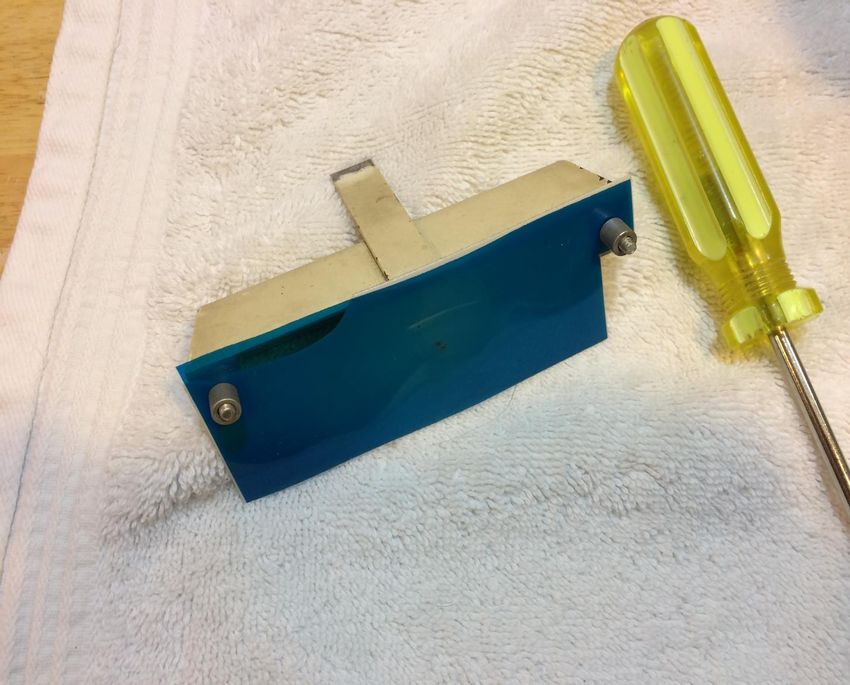
SET PARTS ASIDE AS THEY COME OFF

• What’s wrong with
 this picture?

• Blue gel goes on
 the inside and
 white plastic filter
 on the outside!
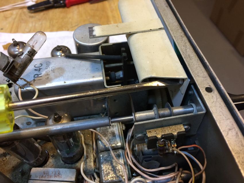
HOW MANY “LEVERS” ARE WE WORKING WITH?

• This TR-4C is a
 36,500 serial #.
 Now a parts rig.
• Note the no-lever,
 one idler gear
 train, all plastic
 gear design of this
 early TR-4C.
HOW MANY “LEVERS” ARE WE WORKING WITH?

• One lever, one
 idler gear train, all
 plastic gear design.
• Doesn’t appear to
 exist!
• Let me know if
 find one please!
HOW MANY “LEVERS” ARE WE WORKING WITH?

• Two lever, two
 idler gear trains,
 all plastic gear
 design from mid-
 run of the C-line.
HOW MANY “LEVERS” ARE WE WORKING WITH?

• One lever, two
 idler trains,
 partially metal
 gear design from
 very late run (post
 27K?) of the C-
 line.
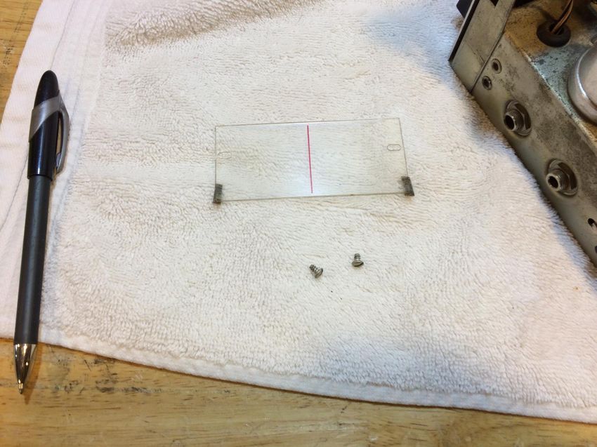
WHERE OH WHERE HAS THE DIAL WINDOW GONE?

• Early C-line dial
 windows were
 mounted inside the
 radio.
• They were mounted
 on the outside of the
 sub-panel later on
• Potentially less
 wear.
WHY WAS THE FELT AGAINST THE SUB-PANEL?

• Felt should have
 been on the dial
 side in this install!
• Re-install window
 on outside of the
 sub-panel when
 done. Remove the
 felt first.
REMOVE THE FRONT PANEL – STEP #1

• Remove all the
 knobs, main dial,
 and sponge bushing.
• Make a note of
 where the spring
 washer style knobs
 go, if you have
 them.
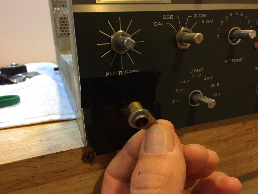
REMOVE THE FRONT PANEL – STEP #2

• Use vinyl tape to
 protect the front
 panel before
 removing the RF
 Gain lever.
• It just slides straight
 off, but rarely easily!
• Prying may be req’d.
REMOVE THE FRONT PANEL – STEP #3
• Use vinyl tape to
 protect the front panel
 Remove the 4 small
 corner screws.
• Using ½” nutdriver,
 remove control nuts.
• Keep and eye out for
 wandering fiber
 washer spacers!
REMOVE THE FRONT PANEL – STEP #4
• Small fiber spacers
 usually fall out –                 Fiber washers usually fall off
                                    – they did not here.
 remove corner screws
 over the towel.
• Use this opportunity to
 clean pots, controls,
 sub-panel, meter face,
 preselector/tune
 controls (on R-4C/T-
 4XC.
REMOVE PTO FROM THE CHASSIS – STEP #1 – TR-4C • Identify 3 wires to be unsoldered – trace thru hole in chassis to PTO; • Green/White – PTO • Red/White – Power (+10V) • Black/White - Ground • Clamp wire with hemostat near terminal and unsolder.
REMOVE PTO FROM THE CHASSIS – STEP #1
 R-4C #28,451
• Identify 3 wires to be
 unsoldered – trace thru
 hole in chassis to PTO;
• Green/White – PTO
• Red/White – Power
 (+10V)
• Black/White - Ground
• Clamp wire with
 hemostat near terminal
 and unsolder.
REMOVE PTO FROM THE CHASSIS – STEP #1
 T-4XC #29,850
• Identify 3 wires to be
 unsoldered – trace thru
 hole in chassis to PTO;
• ***COAX*** – PTO                       COAX
• Red/White – Power
 (+10V)
• Black/White - Ground
• Clamp wire with
 hemostat near terminal
 and unsolder.
REMOVE PTO FROM THE CHASSIS – STEP #2
• Identify 3 nuts to be
 removed holding PTO
 to the chassis;
• Some may have locks
 or flat washers.
• Use a ¼” nutdriver to
 remove the nuts.
• Magnetic probe helps
 retrieve lost hardware.
REMOVE PTO FROM THE CHASSIS – STEP #3
• While holding the PTO
 in place, turn rig right
 side up.
• Tilt the PTO slightly
 forward and gently lift
 up and back.
• “Tease” the wires out
 of the chassis hole as
 you remove the PTO.
DISASSEMBLE THE PTO – GOT YOUR CAMERA
 READY?
• Note the position and
 orientation of the snap
 ring and the 1-1/16”
 cupped steel washer.
• The washer is cupped
 outwards.
• The snap ring is not
 tight against the
 washer.
DISASSEMBLE THE PTO – STEP #1
 USE A CAMERA AT EVERY STEP!
• Using the snap ring
 pliers, gently remove
 the snap ring, followed
 by the washer.
• Keep a finger on the
 snap ring as it is easily
 lost!
• Lay the parts out in
 order on the towel as
 you remove them!
DISASSEMBLE THE PTO – STEP #2
 USE A CAMERA AT EVERY STEP!

• Use a small flat-
 bladed screwdriver
 to ease the keeper
 off the idler gear
 shaft.
• Wiggle each side
 and apply slight
 upwards pressure.
DISASSEMBLE THE PTO – STEP #3
 USE A CAMERA AT EVERY STEP!

• Use tweezers or
 needle nose pliers to
 remove the idler shaft
 spring.
• Careful!A small piece
 of panty hose
 stretched over the
 vacuum nozzle will
 help you find these!
DISASSEMBLE THE PTO – STEP #4
 USE A CAMERA AT EVERY STEP!

• Slide the dial
 assembly forward as
 well as the idler gear
 assembly.
• They will separate and
 you can remove both
 assemblies from the
 shaft/frame.
DISASSEMBLE THE PTO – STEP #5
 USE A CAMERA AT EVERY STEP!

• Lay the pieces out   as
 removed.
• This idler gear had two
 fiber washers behind
 the plastic gears.
• Remember - assume
 no two PTO’s are ever
 the same!!! Take pics!
DISASSEMBLE THE PTO – STEP #6
 USE A CAMERA AT EVERY STEP!

• Carefully remove the
 two, or more, tiny
 brass rivets using a
 pair of small
 diagonal cutters.
• This is the no-lever
 PTO version.
DISASSEMBLE THE PTO – STEP #7
 USE A CAMERA AT EVERY STEP!

• This is the later two
 lever version with
 three brass rivets
 holding each dial
 plate.
DISASSEMBLE THE PTO – STEP #8
 USE A CAMERA AT EVERY STEP!

• Usually the brass
 rivets will come out
 easily, but not
 always! Carefully
 pry up with a small
 flat screwdriver.
DISASSEMBLE THE PTO – STEP #9A
 USE A CAMERA AT EVERY STEP!

• Early models will
 have two little tabs on
 the gear the 100’s dial
 snaps into. Carefully
 pry up and remove.
• Clean up the tops of
 the tabs with a sharp
 knife.
DISASSEMBLE THE PTO – STEP #9B
 USE A CAMERA AT EVERY STEP!

• Later PTO versions
 may have up to 3
 spacer washers
 installed.
• Different thicknesses!
• This one had 2 behind
 the dials, and there
 was another one
 between the 2 dials.
DISASSEMBLE THE PTO – STEP #10
 USE A CAMERA AT EVERY STEP!

• Slide the brass
 bushing off the ¼”
 steel shaft.
• Watch for a fiber
 washer at the back
 end. Handle very
 carefully!
DISASSEMBLE THE PTO –
USE A CAMERA AT EVERY STEP!
• Lay out the parts in order on the towel.
CLEAN THE PTO PARTS

• I use electronic style
 hi-density Q-tips
 and 99.9% alcohol.
• Multiple applications
 required on the
 bearing race, front
 and back.
CLEAN THE PTO PARTS

• Amazing results
 after only one
 application!
CLEAN THE PTO PARTS

• Small tight-weave Q-tips
 (MG Chemicals) are
 great for cleaning the
 inside of the idler gear.
• These also work well for
 De-Oxit applications.
• Toothbrush dipped in
 alcohol works well on
 the gear teeth.
CLEAN THE PTO PARTS

• Use 600 grit emery to
 polish the inner
 surface of the brass
 bushing.
CLEAN THE PTO PARTS

• Conduct a “spin
 test”. The brass
 bushing should spin
 easily on the ¼”
 shaft.
CLEAN THE PTO PARTS

• Use a long toothpick,
 or dental pick to dab
 a small amount of
 grease on the
 bearings.
• Only need to do this
 from the back side.
RE-ASSEMBLING THE PTO – STEPS #1AND #2.

• Slide the ¼” fiber washer
 onto the steel shaft, followed
 by the brass bushing; plastic
 gear end first.
• Press the 100’s dial, face up,
 onto the single gear with the
 tabs (older style). Later style
 has 3 rivets.
RE-ASSEMBLING THE PTO – STEP #3

• Slide the dual gear into the
 back of the 100’s dial, so the
 rivets holes face forward.
• Place the Khz dial over the
 gear hub and install the
 rivets (2 or 3). Dental pick
 will help spread the cup.
RE-ASSEMBLING THE PTO

• Dial assembly should
 look like this.
• Dials should spin
 fairly easily.
• If not, use the fine
 emery to polish the
 inner faces of the gear
 hubs.
RE-ASSEMBLING THE PTO – STEP #4

• Assemble the idler
 gear train on its
 shaft.
• “Spin test” the gears.
• Don’t forget the fiber
 washer(s)!
• Refer to your pics for
 orientation!
RE-ASSEMBLING THE PTO – STEP #5

• On this style of PTO,
 the idler gear train
 and the dial
 assembly have to be
 installed at the same
 time to mesh the
 gears.
RE-ASSEMBLING THE PTO – STEP #6

• All meshed! Don’t
 worry about dial
 positioning yet.
• Re-install the
 retaining spring
 washer on the rear of
 the idler gear shaft.
RE-ASSEMBLING THE PTO – STEP #7

• Re-install the cup
 washer with “dish”
 facing out.
• Re-install the snap
 ring on the shoulder
 of the brass bushing.
 It should not be tight
 against the washer.
RE-ASSEMBLING THE PTO – STEP #8

• Re-install the
 tensioning spring
 between the fixed
 rod at the bottom of
 the PTO frame and
 the idler gear shaft.
• Slide it towards the
 front.
RE-ASSEMBLING THE PTO – STEP #9

• Apply one drop of light
 oil to the steel shaft
 just ahead of the brass
 bushing. Wipe away
 any excess.
• You may have to apply
 a TINY bit to the
 threaded shaft inside
 the frame as well.
BENCH TEST AND INITIAL ALIGNMENT

• Rotate the dials so the short
 end of the roll pin on the ¼”
 shaft, just in front of the
 bearing race is pointing at the
 small tab on the rear of the
 plastic gear.
BENCH TEST AND INITIAL ALIGNMENT
• If you have a frequency counter…..
• Install the sponge bushing and the
 main tuning knob on the shaft.
• Connect 10 VDC to the red/white
 wire, blk/white to ground, and the
 counter input to the green/white.
• Tune the PTO to read 5.155 Khz on
 the counter.
BENCH TEST AND INITIAL ALIGNMENT

• Release the idler gear
 train (and clamp if
 possible), hold the main
 tuning dial from moving,
 and rotate the dials to
 read 300 at the 12
 o’clock position.
• Re-engage the idler(s).
BENCH TEST AND INITIAL ALIGNMENT

• Without a freq counter...
• Position the roll pin as
 described.
• Set the yoke on the PTO
 shaft at it’s midpoint.
• Release the idler, hold the
 main tuning knob, and set
 the dials for 250 at 12
 o’clock.
• Re-engage the idler.
RE-INSTALL THE PTO

• Go back to Slide # 20 and reverse the steps.
• Refer to the pictures you took for re-wiring.
• When done, you may need to reset the PTO slightly.
• Use a sig gen, tx at very low power, or xtal calibrator (just
 be sure you are on the right harmonic!).
FINAL TIPS
• Make sure the dial window goes back in on the front side of
 the sub-panel.
• Leave the light bracket off until you are sure the dials are
 calibrated…but…protect the lamp socket from shorting!
• If necessary, use a 3/32” Allen Key to adjust the PTO ball
 screw ‘tightness’. It’s much easier to do with the PTO can
 removed, which, frankly, is not easy to do! Adjust in VERY
 small increments of only 1-2 degrees at a time!
FINAL TIPS
• PTO failures…I have only seen two, and both had failed
 Zener diodes (CR6) and/or a failed tantalum cap on the
 same +10V line as the Zener. Early PTO’s (before the C-
 line) did not have the cap (C151 in the R-4C; C126 in the T-
 4XC; C227 in the late TR-4C’s), and both 1uf and 10uf were
 used, depending on whether an rx or tx, and serial #.
 Replace with a 10uf/25V electrolytic.
Questions & Answers
      Ron, WB4HFN
      Mark, WB0IQK
      Jeff, WA8SAJ
      Peter, VE7PS
You can also read