Feather Duster ARF _ ASSEMBLY MANUAL
←
→
Page content transcription
If your browser does not render page correctly, please read the page content below
Feather Duster ARF
_________________ ASSEMBLY MANUAL ________________

Specifications

Wingspan: ………………     34.5 in (876.3mm)              Motor size: ………… 480 size brushless
Length: .………………….    29.0 in (736.60mm)
Wing Area: ……….…….   660 sq in (42.58 sq dm)
Weight: …………………      20.0–29.0 oz (623.7g–22.13g)   Radio: ……………….. 4-channel w/2 servos
2
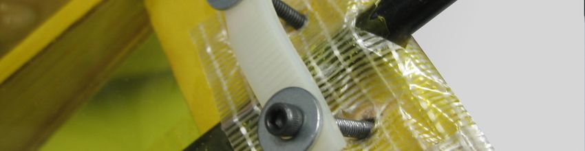
Table of Contents
Table of Contents . . . . . . . . . . . . . . . . . . . . . . . . . . . . . . . . . . . . . . . . . . . . 3
Introduction . . . . . . . . . . . . . . . . . . . . . . . . . . . . . . . . . . . . . . . . . . . . . . . . . 4
Warranty Information. . . . . . . . . . . . . . . . . . . . . . . . . . . . . . . . . . . . . . . . . . 5
Contents of Kit . . . . . . . . . . . . . . . . . . . . . . . . . . . . . . . . . . . . . . . . . . . . . . . 6
Required Radio and Motor Equipment. . . . . . . . . . . . . . . . . . . . . . . . . . . . . 7
Additional Tools and Supplies Required . . . . . . . . . . . . . . . . . . . . . . . . . . . 8
Section 1: Installing the Elevons . . . . . . . . . . . . . . . . . . . . . . . . . . . . . . . . . 9
Section 2: Installing the Servos . . . . . . . . . . . . . . . . . . . . . . . . . . . . . . . . . . 12
Section 3: Installing the Receiver . . . . . . . . . . . . . . . . . . . . . . . . . . . . . . . . 14
Section 4: Installing the Battery Strap Assembly . . . . . . . . . . . . . . . . . . . . . 18
Section 5: Installing the Landing Gear . . . . . . . . . . . . . . . . . . . . . . . . . . . . 20
Section 6: Installing the Motor Mount. . . . . . . . . . . . . . . . . . . . . . . . . . . . . . 22
Section 7: Installing the Electronic Speed Controller . . . . . . . . . . . . . . . . . 24
Section 8: Installing the Control Linkage . . . . . . . . . . . . . . . . . . . . . . . . . . . 27
Section 9: Installing the Rear Hatch . . . . . . . . . . . . . . . . . . . . . . . . . . . . . . 28
Section 10: Installing the Vertical Fins . . . . . . . . . . . . . . . . . . . . . . . . . . . . 30
Section 11: Installing the Battery . . . . . . . . . . . . . . . . . . . . . . . . . . . . . . . . 31
Section 12: Control Throw Recommendations . . . . . . . . . . . . . . . . . . . . . . 32
Section 13: Balancing the Aircraft . . . . . . . . . . . . . . . . . . . . . . . . . . . . . . . 33
Pre-Flight at the Flying Field . . . . . . . . . . . . . . . . . . . . . . . . . . . . . . . . . . . . 34
AMA Safety Code . . . . . . . . . . . . . . . . . . . . . . . . . . . . . . . . . . . . . . . . . . . . 35

                                                                                                                   3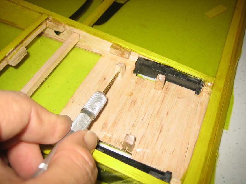
Introduction

Thank you for purchasing the Feather Duster ARF, which is based on the popular Diamond
Dust high performance delta wing aircraft. Backed by Diamond Dust’s high quality reputation,
the Feather Duster will provide you with the superior performance and features you are
looking for in an aerobatic park flyer. The Feather Duster features lightweight balsa and light-
ply construction, high quality aluminum landing gear. This lightly loaded delta wing design
makes it ideal for extremely aggressive maneuvers as well as excellent low speed
maneuverability.

Before Starting Assembly

Before beginning the assembly of your Feather Duster, remove each part from the box and
its bag for inspection. Closely inspect the airframe, airframe components and parts bag for
damage. If you find any damaged or missing parts, contact the place of purchase.

Using the Manual

This manual is divided into sections to help make assembly easier to understand, and to
provide breaks between each major section. Remember to take your time and follow the
directions closely.

Trademarks

E-flite™ is a registered trademark of Horizon Hobby.
Hitec™ is a registered trademark of Hitec RCD USA
Castle Creations™ is a registered trademark of Castle Creations, Inc.
Thunder Power™ is a registered trademark of Thunder Power RC
Other brand or product names are trademarks of their respective holders.

4
Warranty Information

Tetracam, Inc. guarantees this ARF to be free from defects in both material and
workmanship at the date of purchase. This warranty does not cover any component parts
damage by use or modification. In no case shall Tetracam, Inc’s liability exceed the original
cost of the purchased kit. Further, Tetracam, Inc. reserves the right to change or modify this
warranty without notice.

In that Tetracam, Inc. has no control over the final assembly or materials used for the final
assembly, no liability shall be assumed nor accepted for any damage resulting from the
use of the final assembled product . By the act of using the assembled product, the user
accepts all resulting liability. Please note that once assembly of the model has been
started, you must contact Tetracam, Inc. directly regarding any warranty questions. Please
do not contact your local hobby shop regarding warranty issues, even if that is where you
purchased it. This will enable Tetracam to better answer your questions and service you in
the event that you may need any assistance. If the buyer is not prepared to accept the
liability associated with the use of this product, the buyer is advised to return this
kit immediately in new and unused condition to the place of purchase.

                                      Tetracam, Inc
                                      Devonshire St.
                                         Suite 310
                                  Chatsworth, CA 91311
                                  Sales - (818) 718 -2119
                               Tech Support – (352) 375-2911
                                    www.tetracam.com

                                                                                                 5
Contents of Kit

Main Box                                        Hardware Bag Cont.

Qty Description                                 Qty Description

1    Assembly manual                            1     Velcro (Hook side w/ adhesive)
1    Main wing / airframe                                L140mm x W25mm
2    Elevon with C.A. hinges attached           2     Velcro (Loop side w/ adhesive)
2    Vertical Fin assemblies                             L30mm x W25mm
1    Aluminum landing gear                      2     Velcro (Hook side w/ adhesive)
1    Rear hatch assembly                                 L30mm x W25mm
      L155mm x W93mm                            2      80mm foam/plastic wheels
                                                1      Plastic antenna pull tube
                                                1     10mm x 38mm carbon tube
Hardware Bag                                    2      2-56 nylon clevis
                                                1      Predrilled nylon strap
                                                        L45mm x W8.7mm
Qty Description
                                                2      Control horns (nylon)
                                                2      Control horn clip (nylon)
3    M3 x 20mm bolts                            6      C.A. Hinges
2    M3 x 18mm bolts                            1      Nylon tail skid clip
7    M3 nuts                                    1      Motor mount (Aluminum)
5    M3 flat washers
7    2.3mm x 8mm screws
6    2.3mm x 10mm screws
1    Wire tail skid
2    1.5mm x 30mm wire rod
2    1.5mm threaded push rod
4    Hardwood blocks 11.5mm x 6.35mm x
        6.35mm
2    Double sided tape 30mm x 30mm
1    Velcro (Hook side non adhesive)
        L190mm x W25mm
1    Velcro (Loop side w/ adhesive)
        L300mm x W25mm

Warning

An RC aircraft is not a toy! If misused, it can cause serious bodily harm and damage to
property. Fly only in open areas, perferably at AMA (Academy of Model Aeronautics)
approved flying sites, following all instructions included with your radio and equipment.

6
Required Radio and Motor Equipment

Radio Equipment                          (Recommended Items)
  • 1 - 4 channel radio system

  • 2 - Mini Metal Gear Servos (Hitec™
    HS85MG recommended or
    equivalent)

  • 1 - 18” Servo Extension Lead

Motor / Power System
  • Electric Prop (APC™ 10x7SF)
  • 2100mA 3 Cell Li/Po Battery
    (Thunder Power™)
  • 480 size brushless Outrunner (E-
    flite™ Park 480 / 1020kv)
  • 25 Amp Brushless ESC
    (Castle Creations™ or E-Flite™)

     Note: We have included our
     recommended equipment in
     parentasis.

                                                               7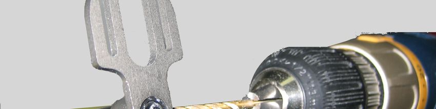
Additional Required Tools and Adhesives

Tools                                            Adhesives
    •   Drill
    •   Drill bits: 1/16”or 1.5mm, 1/8” or 3mm     •   5 or 6 min Epoxy
    •   Hobby Knife                                •   Thin CA Glue
    •   #1 Phillips Screwdriver                    •   Thick CA Glue
    •   Scissors                                   •   CA Accelerator
    •   ¾” Transparent tape                        •   CA Remover / Debonder
    •   2.5mm hex driver
    •   Pliers                                   Other required Items
                                                   •   Epoxy Brushes
                                                   •   Epoxy mixing sticks
                                                   •   Paper Towels
                                                   •   Rubbing Alcohol

8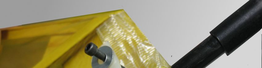
Section 1: Installing the Elevons
   Step 1                                             Step 2

Locate the 2 elevons. Insert 3 hinges in the    Make sure you accurately center your hinges
precut hinge slots on the elevons. You may      in the slots on both the trailing edge of the
need to re-cut the covering over the hinge      airframe and the leading edge of the elevons.
slots with your hobby knife.

NOTE: Before proceeding, make sure that
the elevons are properly orientated. The
control horn mounting blocks should be
located towards each other at the center of
the airframe directly behind the fin sockets.

                                                                                            9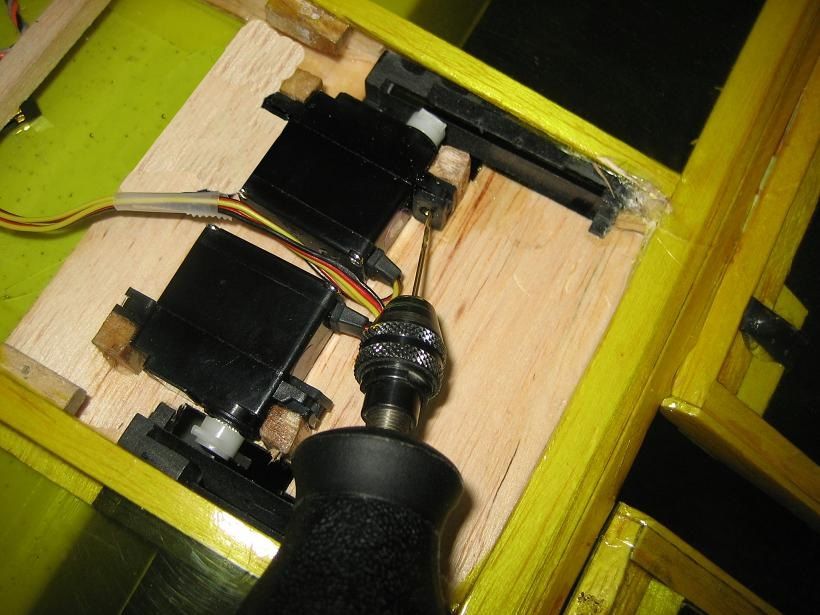
Section 1: Installing the Elevons – Cont.

     Step 3                                          Step 4

Use a ruler or a strait edge and make sure to   Apply thin CA to both sides of each hinge.
align the outside edges of the elevons to be    Make sure the hinge is fully saturated with
flush with the outside wing tip. Slide the      glue. Use a paper towel and CA
elevon and wing together. There should be a     remover/debonder to clean up any excess
small gap between the elevons and the           glue from the wing and or/ elevon.
trailing edge of the wing, approximately
1/64”or 1.5mm.

                                                     Step 5
                                                Firmly grasp the wing and elevon and gently
                                                pull on the elevon to ensure the hinges are
                                                secure and cannot be pulled apart. Use
Note: Do not use CA Accelerator during the
                                                caution when gripping the wing and elevon
  hinge gluing process. The thin CA must be
                                                to avoid crushing the structure.
  allowed to soak into the hinge and balsa in
  order to provide the best bond possible.
  Using accelerator will not provide enough
  time for this process.

10
Section 1: Installing the Elevons – Cont.
Step 6 Step 7
Work the elevons up and down several Locate the control horns and the control horn
times to work in the hinges and check for clips from the parts bag. With a hobby knife,
proper movement. cut a small slit in the covering on both top
and bottom of the control horn mounting
blocks on each elevon.
Apply a small amount of 5 min epoxy on
each control horn and insert them through
the slots.
Install the control horn clips on the bottom of
the control horns, and press them until they
are flush with the bottom of the block. and
apply a small amount of 5 min epoxy to the
clips after they are pressed in.
11Section 2: Installing the Servos
Step 1 Step 3
Locate your servos and install the control Hold the servos in place by using a piece of
horns so they are at the center of the servo’s ¾” transparent tape. Locate the four 11.5mm
travel range. x 6.5mm x 6.5mm small hardwood blocks.
These will need to be installed in order to
install the servos. Glue a block on each side
of each servos using thick CA.
Step 2
Place the airframe upside down on a flat
surface so the trailing edge of the airplane
extends over the edge of your work surface.
Place the servos so the servo arms are
centered in the servo arm openings
And make sure that the larger part of the
case offset is facing the front of the aircraft. Note: It is important that you NOT use larger
servos than the ones we have
recommended. This will reduce the clearance
needed to clear the tail skid block and hatch
cover.
12Section 2: Installing the Servos – Cont.
Step 4 Step 6
When both sets of blocks are dry, mark the Install both servos with the hardware
pilot holes with the 1/16” or 1.5mm drill bit. supplied with your servos. You can also add
to the mounting strength by using the
supplied 30mm x 30mm double sided tape on
the bottom of the servos. Route the servo
leads forward between the servos into the
empty part of the airframe and move on to
the next section
Step 5
Remove the servos and finish drilling the
servo mounting holes
13Section 3: Installing the Receiver
Step 1 Step 3
The receiver should be positioned If you are using a standard receiver you will
somewhere if front of the two servos. need to feed the receiver antenna through
Depending on your receiver type and brand, the antenna tube. If you are using a spread
You will need to make sure that the location spectrum receiver, you can skip to step 8.
you choose will allow the hatch to clear when
it is installed. Step 4
Locate the antenna pull tubing which is the
small tube that should be located inside one
of the parts bags.
Cut a small slit half way through the pulling
tube approximately ½” from one end.
Step 2
Connect your servo leads to their appropriate
channels. Apply the small 30mm x 25mm
hook side of Velcro supplied with the kit on
Your chosen location on the aircraft. Then
use the small 30mm x 25mm loop side of
Velcro on your receiver.
14Section 3: Installing the Receiver – Cont.
Step 5 Step 6
Pull the short semi-cut section back to open
the tube so you can insert the end of the
antenna in the open end on the short side of Insert the opposite end of antenna pull tube
the cut. into one side of the antenna tube and feed it
through until it comes out the other side.
Next, straiten out the short piece so it
pinches the antenna in the pull tube.
15Section 3: Installing the Receiver – Cont.
Step 7 Step 8
Pull the exposed pull tube until the antenna is
completely pulled through the antenna tube. Spread spectrum receivers do not have long
antenna leads but may have a dual antenna
system.
Then mount your receiver as described in
Step 2. You can now skip step 8 and go to The dual antenna module can be installed by
step 9 in this section to continue. placing the dual antenna module inside the
airframe with Velcro.
Try and place the separate antenna module
as far forward as you can. The use of a long
screwdriver or needle nose pliers can be
helpful.
NOTE: Be sure to keep the pull tube for
future use in case you decide to remove or
install a new receiver.
16Section 3: Installing the Receiver – Cont.
Step 9 Step 9 – cont.
Now is a good time to check your servo When looking down at the servo arms from
directions and radio programming. the top of the aircraft, the right servo arm
should move forward and the left servo arm
When looking down at the servo arms from should move back when right aileron input is
the top of the aircraft, both servo arms should fed to your transmitter.
move forward when the elevator is pulled up
on your transmitter.
Both servos arms pull forward Left servo arm pulls back
Right servo arm pulls forward
Tip: You may need to swap servo channels Note: If your radio does not support delta
or servo directions in order to achieve proper wing configuration or allow you to program
movement from your radio system. elevator / aileron mixing, you will need a v-
tail mixer.
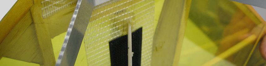
17Section 4: Installing the Battery Strap Assembly.
Step 1 Step 3
Locate the following parts from the parts bag: On the 190mm non adhesive Velcro strap,
make two small cuts approximately 8mm to
• Velcro (Hook side non adhesive)
L190mm x W25mm 10mm in length about 150mm apart.
• Velcro (Hook side w/ adhesive)
L140mm x W25mm
• (2) 1.5mm x 30mm wire rods
Step 2 Step 4
Slide the Velcro on the battery straps making
Apply the 140mm hook side Velcro to the sure that the hook sides are facing each
center area in between the two battery straps other.
on the airframe.
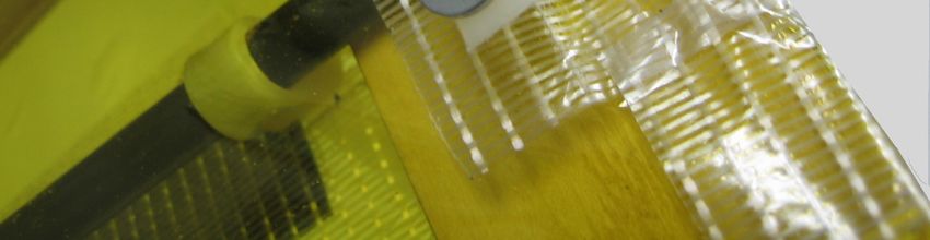
18Section 4: Installing the Battery Strap Assembly- cont.
Step 5 Step 7
Insert both short 1.5mm rods halfway into the Using 5 minute epoxy, apply a small amount
predrilled holes found on the nylon battery of epoxy at the location where the pins go
straps. Make sure that the Velcro is located through the battery straps. Do this to both
below the holes and that the hook side of the sides of the straps.
Velcro is again facing each other.
NOTE: Do not use CA glue on the nylon
straps. The CA glue will harden the straps
and make them brittle. This can cause the
battery mount straps to break in flight and
cause your aircraft to crash.
Step 6
Once the two metal pins have been inserted,
push the Velcro down against the covering in
order to move it away from the pins.
19Section 5: Installing the Landing Gear
Step 1 Step 3
Attach the first M3 nut and leave 1mm
Locate the following parts from the parts bag: of play so the wheel can turn freely.
• (2) M3 x 20mm bolts
• (2) M3 washers
• (4) M3 nuts
Assemble each wheel axles as per the
diagram below.
Step 4
Then install the wheel to the landing gear
using the second M3 nut and then tighten the
outside nut against the landing gear.
Step 2
Recheck the 1mm of play to ensure that the
wheel still turns freely.
Place a washer on the bolt first and then
insert the bolt through the wheel.
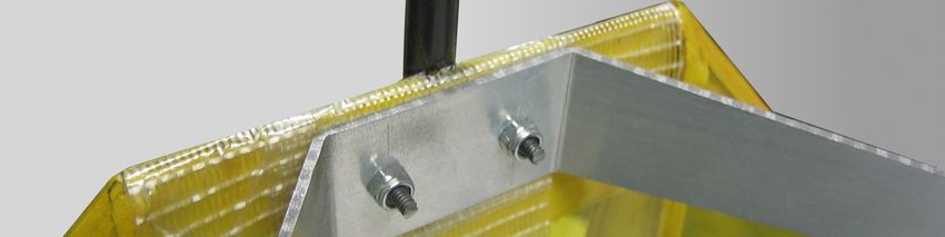
20Section 5: Installing the Landing Gear – Cont.
Step 5 Step 6
Locate pre-drilled nylon strap (45mm x
8.7mm). Insert two M3 x 18mm bolts with
washers through the holes in the nylon strap Attach the landing gear underneath the motor
and insert the bolt and strap assembly mount plate using two M3 nuts. Make sure to
through the two 1/8” holes in the motor mount tighten back and forth between the two bolts
plate, over the carbon tube. in order to insure that the strap is evenly
tightened.
21Section 6: Installing the Motor Mount
Step 1 Step 3
Locate the short 10mm x 38mm Carbon
Tube supplied with the kit is used to help Slide the motor mount over the 10mm tubing
makeup the gap between the motor mount and make sure that the mount is vertically
and the 8mm carbon tubing. strait as well as flush with the end of the
carbon tubing.
Step 2
Next, drill through both layers of the carbon
tubing on the right side of the motor mount
Slide the 10mm tube over the 8mm carbon
only.
tube until it is flush with the end of the 8mm
tube. Apply 1 drop of thin CA at the end to
secure both tubes temporarily
22Section 6: Installing the Motor Mount – cont.
Step 4 Step 5
Next bolt the motor mount on the carbon tube
using a M3 x 20mm bolt, an M3 washer and
M3 nut.
Drill through both layers of carbon tubing on
the left side of the motor mount.
Install your motor to the motor mount with the
hardware supplied with your motor.
23Section 7: Installing the Electronic Speed Controller
Step 1 Step 3
Cut a small slot approximately 10mm long in Feed the rest of the servo extension in the
the fiberglass packing tape area on the hole leaving the last ½” of the lead exiting the
bottom of the aircraft next to the rear battery hole.
strap.
Tip: Hold the aircraft vertically and feed the
servo extension towards the rear hatch area
by gently shaking the airframe.
Note: you can use a small soldering iron or
heated flat head screwdriver to cauterize the
hole after it has been cut to increase the
strength of the hole.
Step 2
Next feed the female end of the 18” servo
extension into the hole.
24Section 7: Installing the Electronic Speed Controller – cont.
Step 4 Step 6
Install the servo extension lead to your
receivers throttle channel. Apply the loop side of the small 30mm x
25mm Velcro strip to the back side of your
speed controller.
Step 5 Step 7
Connect the servo lead on your speed
Locate one of the 30mm x 25mm Velcro
controller to the servo extension and install
strips. Install the hook side about midway
the speed controller to the Velcro you added
down the battery strap area and off to the
to the airframe in step 5.
side about halfway over the fiberglass tape.
25Section 7: Installing the Electronic Speed Controller – cont.
Step 8 Step 10
Using a small piece of ¾” transparent tape,
tape the servo extension and speed Connect the motor leads to your speed
controller lead together in order to prevent controller.
them from coming apart.
NOTE: You can use a few pieces of
transparent tape to secure your wires to the
airframe. You also want to make sure that
your motor and speed controller wires are as
close to the airframe as possible. Wires that
hand too low can be unsafe during takeoffs
and landings as the wires can get caught on
obstacles on the ground.
Step 9
Feed the rest of the servo lead into the hole
and pull enough out the hatch area to leave a
small loop at the controller.
26Section 8: Installing the Control Linkage
Step 1 Step 3
Locate the following parts from the parts bag. Install each pushrod on their respective
• (2) 1.5mm threaded push rods servos arms.
• (2) 2-56 nylon clevis
Step 4
Step 2
Thread the clevis on each push rod so Attach the clevis to the control horns and re-
the distance between the clevis pin and the z check to make sure that the elevons are in
bend is approximately 70mm. their neutral positions when the servo arms
are in their center positions.
NOTE: The 70mm distance is a general
starting length. You should make final
adjustments to the length of each pushrod so
the elevon is in the center or neutral position
when the servo arm is in the center of its
range of motion.
27Section 9: Installing the Rear Hatch
Step 1 Step 3
Locate the following from the parts bag. Screw the hatch on using the (7) 2.3mm x
• (7) 2.3 x 8mm screws 8mm screws in the predrilled holes.
• (2) 2.3mm x 10mm screws
• Nylon tail skid clip
• Wire tail skid
Step 2
Locate the rear hatch assembly from the
main box and place it over the servo bay.
If there is interference between the servos
and the tail skid block, trim away the
necessary amount to ensure proper
clearance of the servos.
28Section 9: Installing the Rear Hatch – cont.
Step 4 Step 5
Insert the wire tail skid in the center hole on
the rear of the hatch. Screw the nylon clip down using the (2)
2.3mm x 10mm screws.
Next, place the nylon tail skid clip over the
tail wire and line up the holes in the clip to
the predrilled holes on the rear hatch. screws
29Section 10: Installing the Vertical Fins
Step 1 Step 3
Locate the two vertical fin assemblies from Temporarily remove the clevis from the
the main box. control horns and swing the control linkage
forward. This will allow you to access the
screws holes on the fin sockets.
Step 2
Insert both vertical fins into the fin sockets on
the rear of the aircraft.
Step 4
Secure the fins using (2) 2.3mm x 10mm
Screws per socket. Do this for both fins.
30Section 11: Installing the Battery
Step 1 - Battery preparation Step 2 - Battery installation
The following step is performed only once While holding the top Velcro strap away from
per battery pack. the aircraft, place the battery in the center of
the battery area. Next gently press the Velcro
Locate the long 300mm x 25mm loop side
strap down on to the battery. This should
Velcro from the parts bag.
secure the battery between the two Velcro
surfaces.
Clean the battery with rubbing alcohol and a
paper towel in order to remove any grease or
dirt.
Apply the Velcro around the battery so both
sides of the battery are covered with Velcro
and trim off any excess.
Step 3 - Battery removal
Gently pull the Velcro strap away from the
battery. While holding the strap, use the other
hand to pull the battery away from the battery
area.
NOTE: You will need additional Velcro for
any extra batteries. You can use any loop NOTE: Velcro has a very strong bond. Take
side Velcro which can be obtained at most care and be patient while removing the
home improvement stores. battery so you don’t damage the aircraft.
31Section 12: Control Throw Recommendations
Step 1 Control Throws
Give the aircraft a complete check over and
make sure the airframe and all control
surfaces are straight.
Also make sure that with up and down
elevator your elevons stay equal through
their range of motion.
Start out with 1 IN. up & 1 IN. down with both
elevator & aileron, then crank up the elevator
until it starts to stall & crank up the ailerons
until the rolls slow down or YOU YELL
UNCLE.
We recommend that you use 100% expo on
your ailerons and 25% on your elevator for
the test flight.
Low Rate High Rate
Elevator 1” (15 deg.) up 2” (25 deg.) up
1” (15 deg.) down 2” (25 deg.) down
Make sure that you have the proper direction
Aileron 1” (15 deg.) up 2” (25 deg.) up in relation to your radio moves.
1” (15 deg.) down 2” (25 deg.) down
32Section 13: Balancing the Aircraft
Step 1
Recommended CG It is suggested to start at the forward end of
the range until comfortable with the flight
An important part of preparing the aircraft for characteristics of your aircraft.
flight is properly balancing the model. This is
especially important when using different If necessary, you can move the battery pack
battery packs. forward or rearward in the battery area or
add weight to either the nose or the tail until
The recommended Center of Gravity (CG) for the correct balance is achieved. Stick-on
the Feather Duster is at the high point of the weights are available at your local hobby
main ribs to ½” in front of the main ribs. shop and work well for this purpose.
To properly check the balance the aircraft,
suspend the plane with your fingers on the
leading edge of the wing where the main
spar intersects the leading edge.
33Preflight at the field
Step 1 Step 2
Preflight check Range testing the Radio
Charge both the transmitter and receiver Before each flying session, range-check your
pack for your airplane. Use the re- radio. This is accomplished by turning on
commended charger supplied with your your transmitter with the antenna collapsed.
particular radio system, following the Turn on the radio in your airplane. With your
instructions provided with the radio. In most airplane on the ground, you should be able to
cases the radio should be charged the night walk 30 paces away from your airplane and
before going out flying. still have complete control of all functions.
Check the radio installation and make sure If not, don't attempt to fly! Have your radio
all the control surfaces are moving correctly equipment checked out by the manufacturer.
(i.e. the correct direction and with the
recommended throws). Step 3
Initial Instructions for takeoff
Check all the control horns, servo horns and Make sure you place the aircraft on smooth
clevises to make sure they are secure and in level ground with the nose pointing into the
good condition. Replace any items that would wind. When you are ready to take off, open
be considered questionable. Failure of any of the throttle up to full throttle and add a slight
these components in flight would mean the bit of up elevator. The aircraft should fly off
loss of your aircraft. the ground with no other inputs. Once
airborne, the aircraft can be flown like any
other aircraft.
Note! Difficulties will arise and you will run
the risk of cart wheeling the aircraft, if you try
and feed in a lot of elevator at the time of
take off. Just relax, and increase throttle till
the aircraft takes off and then when airborne,
start flying!
342007 AMA National Model Aircraft Safety Code
2007 Official Academy of Model Aeronautics National Model Aircraft Safety
Code Effective January 1, 2006
GENERAL
1. A model aircraft shall be defined as a non-human-carrying device capable of sustained
flight in the atmosphere. It shall not exceed limitations established in
this code and is intended to be used exclusively for recreational or competition activity.
2. The maximum takeoff weight of a model aircraft, including fuel, is 55 pounds, except for
those flown under the AMA Experimental Aircraft Rules.
3. I will abide by this Safety Code and all rules established for the flying site I use. I will not
willfully fly my model aircraft in a reckless and/or dangerous
manner.
4. I will not fly my model aircraft in sanctioned events, air shows, or model demonstrations
until it has been proven airworthy.
5. I will not fly my model aircraft higher than approximately 400 feet above ground level,
when within three (3) miles of an airport without notifying the
airport operator. I will yield the right-of-way and avoid flying in the proximity of full-scale
aircraft, utilizing a spotter when appropriate.
6. I will not fly my model aircraft unless it is identified with my name and address, or AMA
number, inside or affixed to the outside of the model aircraft. This
does not apply to model aircraft flown indoors.
7. I will not operate model aircraft with metal-blade propellers or with gaseous boosts
(other than air), nor will I operate model aircraft with fuels containing
tetranitromethane or hydrazine.
8. I will not operate model aircraft carrying pyrotechnic devices which explode or burn, or
any device, which propels a projectile of any kind. Exceptions
include Free Flight fuses or devices that burn producing smoke and are securely attached
to the model aircraft during flight. Rocket motors up to a G-series
size may be used, provided they remain firmly attached to the model aircraft during flight.
Model rockets may be flown in accordance with the National Model
Rocketry Safety Code; however, they may not be launched from model aircraft. Officially
designated AMAAir Show Teams (AST) are authorized to use
devices and practices as defined within the Air Show Advisory Committee Document.
9. I will not operate my model aircraft while under the influence of alcohol or within eight
(8) hours of having consumed alcohol.
3510. I will not operate my model aircraft while using any drug which could adversely affect my ability to safely control my model aircraft. 11. Children under six (6) years old are only allowed on a flightline or in a flight area as a pilot or while under flight instruction. 12. When and where required by rule, helmets must be properly worn and fastened. They must be OSHA, DOT, ANSI, SNELL or NOCSAE approved or comply with comparable standards. RADIO CONTROL 1. All model flying shall be conducted in a manner to avoid over flight of unprotected people. 2. I will have completed a successful radio equipment ground-range check before the first flight of a new or repaired model aircraft. 3. I will not fly my model aircraft in the presence of spectators until I become a proficient flier, unless I am assisted by an experienced pilot. 4. At all flying sites a safety line or lines must be established, in front of which all flying takes place. Only personnel associated with flying the model aircraft are allowed at or in front of the safety line. In the case of airshows or demonstrations a straight safety line must be established. An area away from the safety line must be maintained for spectators. Intentional flying behind the safety line is prohibited. 5. I will operate my model aircraft using only radio-control frequencies currently allowed by the Federal Communications Commission (FCC). Only individuals properly licensed by the FCC are authorized to operate equipment on Amateur Band frequencies. 6. I will not knowingly operate my model aircraft within three (3) miles of any preexisting flying site without a frequency-management agreement. A frequency-management agreement may be an allocation of frequencies for each site, a day-use agreement between sites, or testing which determines that no interference exists. A frequency-management agreement may exist between two or more AMA chartered clubs, AMA clubs and individual AMA members, or individual AMA members. Frequency-management agreements, including an interference test report if the agreement indicates no interference exists, will be signed by all parties and copies provided to AMA Headquarters. 7. With the exception of events flown under official AMA Competition Regulations rules, excluding takeoff and landing, no powered model may be flown outdoors closer than 25 feet to any individual, except for the pilot and the pilot's helper(s) located at the flightline. 36
8. Under no circumstances may a pilot or other person touch a model aircraft in flight while
it is still under power, except to divert it from striking an
individual.
9. Radio-controlled night flying is limited to low-performance model aircraft (less than 100
mph). The model aircraft must be equipped with a lighting system
which clearly defines the aircraft's attitude and direction at all times.
10. The operator of a radio-controlled model aircraft shall control it during the entire flight,
maintaining visual contact without enhancement other than by
corrective lenses that are prescribed for the pilot. No model aircraft shall be equipped with
devices which allow it to be flown to a selected location which is
beyond the visual range of the pilot.

FREE FLIGHT
1. I will not launch my model aircraft unless I am at least 100 feet downwind of spectators
and automobile parking.
2. I will not fly my model aircraft unless the launch area is clear of all individuals except my
mechanic, officials, and other fliers.
3. I will use an effective device to extinguish any fuse on the model aircraft after the fuse
has completed its function.

CONTROL LINE
1. I will subject my complete control system (including the safety thong where applicable)
to an inspection and pull test prior to flying. The pull test will be in
accordance with the current Competition Regulations for the applicable model aircraft
category. Model aircraft not fitting a specific category shall use those
pull-test requirements as indicated for Control Line Precision Aerobatics.
2. I will ensure that my flying area is clear of all utility wires or poles and I will not fly a
model aircraft closer than 50 feet to any above-ground electric utility
lines.
3. I will ensure that my flying area is clear of all nonessential participants and spectators
before permitting my engine to be started.
SPECIALIZED SUPPLEMENTAL SAFETY CODES, STANDARDS AND REGULATIONS
RADIO CONTROL COMBAT (#525)
GENERAL RADIO CONTROL RACING (#530)
GIANT SCALE RADIO CONTROL RACING (#515-A)
GAS TURBINE OPERATION (Note: Special waiver required) (#510-A)
These special codes and appropriate documents may be obtained either from the
AMAWeb site or by contacting AMA Headquarters.
                                                                                                   37
38
39
© 2007 Tetracam, Inc
        21601 Devonshire Street
                Suite 310
      Chatsworth, California 91311
           www.tetracam.com
         Sales - (818) 718 -2119
     Tech Support – (352) 375-2911

40
You can also read