Aircraft Engineering and Aerospace Technology: An International Journal - atp-aviation.com
←
→
Page content transcription
If your browser does not render page correctly, please read the page content below
Aircraft Engineering and Aerospace Technology: An International Journal
                                                                    Three surface aircraft (TSA) configuration – flying qualities evaluation
                                                                    Tomasz Goetzendorf-Grabowski Tomasz Antoniewski
                                                                    Article information:
                                                                    To cite this document:
                                                                    Tomasz Goetzendorf-Grabowski Tomasz Antoniewski , (2016),"Three surface aircraft (TSA) configuration – flying qualities
                                                                    evaluation", Aircraft Engineering and Aerospace Technology: An International Journal, Vol. 88 Iss 2 pp. 277 - 284
                                                                    Permanent link to this document:
                                                                    http://dx.doi.org/10.1108/AEAT-02-2015-0055
                                                                    Downloaded on: 15 March 2016, At: 02:32 (PT)
                                                                    References: this document contains references to 15 other documents.
                                                                    To copy this document: permissions@emeraldinsight.com
                                                                    The fulltext of this document has been downloaded 14 times since 2016*
Downloaded by POLITECHNIKA WARSZAWSKA At 02:32 15 March 2016 (PT)

                                                                    Users who downloaded this article also downloaded:
                                                                    Krzysztof Piwek, Witold Wi#niowski, (2016),"Small air transport aircraft entry requirements evoked by FlightPath 2050", Aircraft
                                                                    Engineering and Aerospace Technology, Vol. 88 Iss 2 pp. 341-347 http://dx.doi.org/10.1108/AEAT-02-2015-0065
                                                                    Tobias Bach, Tanja Führer, Christian Willberg, Sascha Dähne, (2016),"Automated sizing of a composite wing for the usage
                                                                    within a multidisciplinary design process", Aircraft Engineering and Aerospace Technology, Vol. 88 Iss 2 pp. 303-310 http://
                                                                    dx.doi.org/10.1108/AEAT-02-2015-0057
                                                                    Julian Scherer, Dieter Kohlgrüber, (2016),"Fuselage structures within the CPACS data format", Aircraft Engineering and
                                                                    Aerospace Technology, Vol. 88 Iss 2 pp. 294-302 http://dx.doi.org/10.1108/AEAT-02-2015-0056

                                                                    Access to this document was granted through an Emerald subscription provided by emerald-srm:319438 []
                                                                    For Authors
                                                                    If you would like to write for this, or any other Emerald publication, then please use our Emerald for Authors service
                                                                    information about how to choose which publication to write for and submission guidelines are available for all. Please visit
                                                                    www.emeraldinsight.com/authors for more information.
                                                                    About Emerald www.emeraldinsight.com
                                                                    Emerald is a global publisher linking research and practice to the benefit of society. The company manages a portfolio of
                                                                    more than 290 journals and over 2,350 books and book series volumes, as well as providing an extensive range of online
                                                                    products and additional customer resources and services.
                                                                    Emerald is both COUNTER 4 and TRANSFER compliant. The organization is a partner of the Committee on Publication Ethics
                                                                    (COPE) and also works with Portico and the LOCKSS initiative for digital archive preservation.

                                                                    *Related content and download information correct at time of download.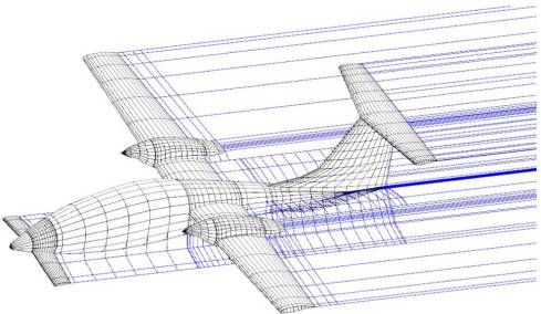
Three surface aircraft (TSA) configuration –
flying qualities evaluation
Tomasz Goetzendorf-Grabowski
Faculty of Power and Aeronautical Engineering, Warsaw University of Technology, Warsaw, Poland, and
Tomasz Antoniewski
AT-P AVIATION Sp. z o.o., Warsaw, Poland
Abstract
Purpose – Unconventional configuration aircrafts are not often designed because of many problems, mainly with stability and trim. However,
they could be very promising. The problems can be compensated by extraordinary performance and some flying characteristics. The
three-surface aircraft, presented in the paper, is such a configuration – problems and profits are both present, but advantages seem to be
more prevalent. This paper aims to present main assumptions for a new, three-surfaces aircraft design, its evaluation according to flying
quality requirements and the discussion on selected performance characteristics. The paper completes with the first experimental results of
flight tests of a 40 per cent scaled model.
Downloaded by POLITECHNIKA WARSZAWSKA At 02:32 15 March 2016 (PT)
Design/methodology/approach – Aerodynamic computations were made using panel method code (KK-AERO, PANUKL). Stability analysis was
done using SDSA package, developed within the SimSAC project.
Findings – Initial design assumptions and numerical analysis results were proven during flight tests.
Practical implications – The paper contains results of numerical analysis, which were crucial in designing the layout of the new, three-surface
aircraft.
Originality/value – This paper presents an original approach to design a new, unconventional aircraft. The approach and results could be useful
in other projects.
Keywords Aircraft design, Stability, Canard, Three-surfaces configuration
Paper type Research paper
Introduction force, especially in the case of front CG position. From the
stability point of view, good characteristics of canard (big lift
Designing a new aircraft is always a challenge, especially when
curve slope) are not desired. Because of that, it was a real
unconventional configuration is considered. Unconventional
challenge to satisfy trim and stability in this range, in each case
configuration is usually the reason of many problems;
of payload.
however, it could be very promising due to extraordinary
This paper presents the design of this three-surface
characteristics – small drag, high performance, etc. The flying
configuration, the stability analysis, its influence on the final
qualities are fundamental from the pilot’s and potential
layout of the aircraft and remarks about flying qualities.
customer’s points of views and have to be tested during the
Selected parameters recorded during test flights of the
conceptual stage of the project (Rizzi, 2011;
scaled model were presented and compared with
Goetzendorf-Grabowski et al., 2011). The paper presents the
calculation results.
stability and trim analysis of a newly designed four-seat
aircraft in a three-surface configuration (Figure 1).
The small aircraft in the presented unconventional Aircraft presentation
configuration requires that trim and stability are taken care of, The fundamental feature of the current aircraft has to be its
due to a very wide movement of gravity centre (CG). The ability to sell. At least one parameter of a newly designed
position of CG in the presented aircraft changes from ⫺22 aircraft must be better in comparison to a competitive aircraft.
to ⫹10 per cent of MAC. The whole payload is located in It is a minimum requirement and it allows only for
front part of the fuselage (between main wing and canard). vegetation – see Mooney, Maule, Aviat, etc. The aircraft,
Canard plays an important role: to satisfy the longitudinal which is willingly bought, must have some parameters
equilibrium. Therefore, it must be able to give a sufficient lift surpassing competition. Usually, there are two basic
performance parameters (i.e. STOL characteristics, payload)
and some features which improve comfort or equipment (i.e.
The current issue and full text archive of this journal is available on
Emerald Insight at: www.emeraldinsight.com/1748-8842.htm
The financial support by Polish Agency for Enterprise Development
(PARP) through co-funding of the project POIG.01.04.00-14-260/11 has
been approved.
Aircraft Engineering and Aerospace Technology: An International Journal
88/2 (2016) 277–284 Received 27 February 2015
© Emerald Group Publishing Limited [ISSN 1748-8842] Revised 26 June 2015
[DOI 10.1108/AEAT-02-2015-0055] Accepted 17 December 2015
277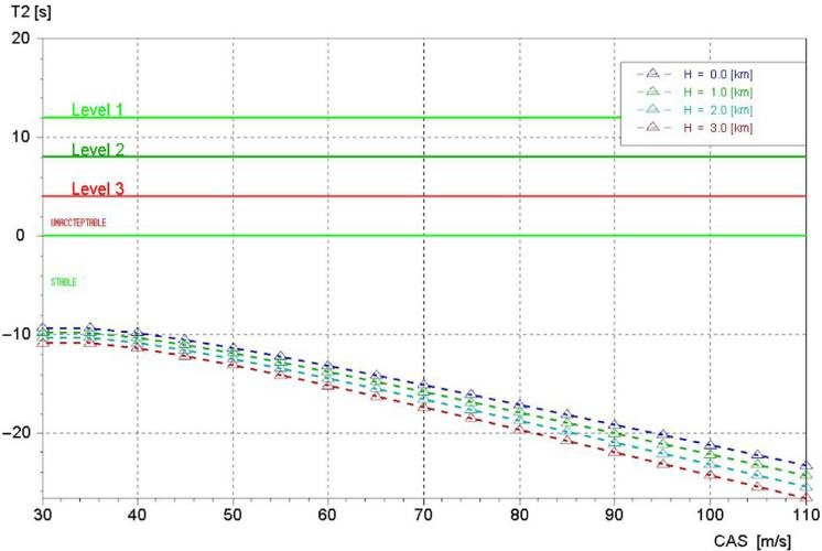
Three surface aircraft (TSA) configuration Aircraft Engineering and Aerospace Technology: An International Journal
Tomasz Goetzendorf-Grabowski and Tomasz Antoniewski Volume 88 · Number 2 · 2016 · 277–284
Figure 1 AT6 – final concept force on the horizontal tail. Thus, the concept of the
three-surface aircraft was born and it was named AT-6.
The presented aircraft is designed using four-seats,
twin-engine configuration. The main geometric, weight and
performance (assumed) parameters are presented in Table I.
The aircraft has slotted flaps on the main wing and plain
flap on the canard. Flaps on the main wing and canard are
coupled. The classical elevator on the horizontal tail is used for
pitch control. The primary configuration had dihedral 3.5°
and relatively big vertical stabilizer (Figure 2). The engines
were located on the upper surface of the wing to fulfil the
requirement of the sufficient clearance between the propeller
and the ground.
advanced avionics, satellite phone, etc.). A good example is Aerodynamic analysis
Cirrus, which has high cruise airspeed, range and sufficient The aerodynamic analysis was done to obtain all
comfort even for tall people. Additionally, it has very good characteristics necessary, next to stability analysis and parallel
Downloaded by POLITECHNIKA WARSZAWSKA At 02:32 15 March 2016 (PT)
onboard equipment. However, the greatest achievement is to to optimizing all details (airfoil, flaps, engine nacelles, etc.).
design an aircraft which has performance parameters The aerodynamic design was made using XFOIL (Drela,
surpassing competition, which are the opposite features, i.e. 1989) and MSES for airfoil design, KK-AERO package
high maximum airspeed and low minimum airspeed or high (Kubryński, 1999), based on panel method with boundary
stability and high manoeuvrability. If we add economics of layer, for 3D design (Kubryński, 2014). Analysis and
use, high level of safety, some nice gadgets onboard and the optimization of the flow around AT-6 was done using ANSYS
reasonable price, the success is almost assured. CFX software (Mazurkiewicz, 2014).
Usually opposite features cause, that price is growing (i.e. Aerodynamic characteristics, including stability derivatives,
complicated superlift devices, expensive power unit, were computed using low-order panel code (PANUKL,
sophisticated and expensive materials, etc.). The classical 2012). Figures 3 and 4 present an example of mesh (primary
configuration of an aircraft, with current engines, does not
give a chance to improve performance characteristics Table I The main geometric, weight and performance parameters
significantly, although new technologies and new
airworthiness regulation, generate some outstanding Wingspan 11.0 m
exceptions (i.e. Cirrus, Diamond, Pipistrel – Panthera). The Length 9.0 m
big chance to obtain a significant increase of opposite Height 3.0 m
parameters could be unconventional configuration. Wing area 12.5 m2
The presented aircraft was designed as a four-seat, Maximum TO weight 1280 kg
twin-engine light aircraft. It had to be comfortable, fast, safe W/S 103 kg/m2
and economical; thus, its name PSE – Performance Safety and Engines power 230 HP
Economy. Safety was satisfied by the use of two engines and a Minimum airspeed 90 km/h
parachute recovery system. The economy was due to two Cruise airspeed (at sea level) 280 km/h
Rotax engines, which are able to use the same fuel that is used Cruise airspeed (at 14000 ft) 320 km/h
by cars. Moreover, advanced aerodynamic project had to give Ceiling 1,8000 ft
good characteristics to improve economy and performance as
well. Additionally, innovative flaps, which are deflected up in
cruise condition and partially retracted to decrease wetted Figure 2 AT6 – primary configuration
area, increase the aerodynamic effectiveness. Initially, the
ergonomics of cabin was the starting point. It had to be free of
other elements because of the convenience, but also because
the cross-sectional area has a large impact on performance.
Thus, the main spar and landing gear were moved out of the
cabin space. The visibility from cabin had to be similar to
visibility from helicopter cabin, not as in small Cessna case, so
it should be a highly glazed cabin. Next – easy entering for
each pilot and passenger, thus one large glazed door for pilots
and two “gull wing” doors for each passenger. These
requirements caused that the wheel base of the landing gear
was increased and, what is most important, the main wing was
shifted back, which caused that CG is located in front of the
leading edge of main wing. Such an extreme CG position
forces the additional lifting surface on the front of fuselage
(canard) to satisfy trim and to decrease a very big, negative
278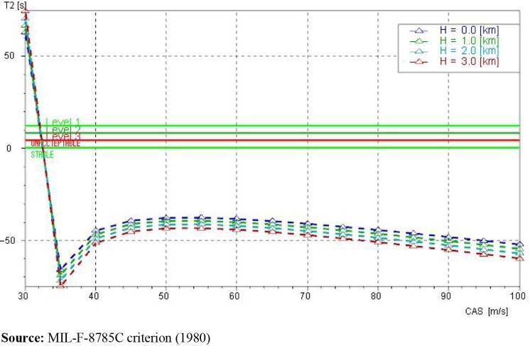
Three surface aircraft (TSA) configuration                    Aircraft Engineering and Aerospace Technology: An International Journal
                                                                            Tomasz Goetzendorf-Grabowski and Tomasz Antoniewski                                Volume 88 · Number 2 · 2016 · 277–284

                                                                    Figure 3 PANUKL computation: Mesh AT6 – primary                            methods – hinge moments and the apparent masses
                                                                    configuration – 3,609 panels                                               (derivatives with respect to acceleration), due to different
                                                                                                                                               reasons. The results of hinge moments obtained using panel
                                                                                                                                               code were not verified, and the apparent masses usually
                                                                                                                                               cannot be computed by used panel code, although some
                                                                                                                                               commercial packages have such ability. Such an approach, i.e.
                                                                                                                                               mix of different data, was verified in some other projects and
                                                                                                                                               gave good results.
                                                                                                                                                  The static margin, which is a basic factor of longitudinal
                                                                                                                                               static stability, was computed for all configurations of the CG
                                                                                                                                               position versus the angle of attack and in consequence versus
                                                                                                                                               airspeed. The value of the static margin in fixed and free stick
                                                                                                                                               cases is shown in Figure 5. It shows, that, in case of the rear
                                                                                                                                               position of CG, which corresponds to a small payload (one
                                                                                                                                               light pilot), the aircraft can be longitudinally unstable in case
                                                                                                                                               of the free stick and for higher airspeed in case of fixed stick as
                                                                    configuration) prepared in the PANUKL package and results                  well. Figure 5 also shows a big difference between rear and
Downloaded by POLITECHNIKA WARSZAWSKA At 02:32 15 March 2016 (PT)

                                                                    of computation for angle of attack equal 7.5°. Basic                       front CG position.
                                                                    characteristics (lift and pitching moment coefficients)
                                                                    obtained from PANUKL allow to determine static margin in                   Dynamic stability analysis
                                                                    fixed stick case (Goetzendorf-Grabowski, 2014). Free stick                 The dynamic analysis was done using the SDSA package,
                                                                    case also requires the hinge moment coefficients of elevator               which is also able to analyze linear and nonlinear models
                                                                    and downwash angle to be computed. Downwash was
                                                                                                                                               (Goetzendorf-Grabowski et al., 2011). All results of dynamic
                                                                    computed by using PANUKL and hinge moments using
                                                                                                                                               stability analysis, including figures of merit, presented in this
                                                                    ESDU reports.
                                                                                                                                               paper, were obtained from SDSA. The assumed model does
                                                                       Most of stability derivatives were computed using the
                                                                                                                                               not take into account the engine effects on flight dynamics;
                                                                    PANUKL package. Missing derivatives, especially derivatives
                                                                    with respect to vertical acceleration, were computed using                 however, the position of thrust vector was taken to determine
                                                                    handbook methods and formulae (Etkin, 1982; Roskam,                        the trim condition. It seems that the drag effect of propellers
                                                                    2003; Goraj, 2014).                                                        can improve directional stability a little because it increases the
                                                                       The assumed methodology to obtain all necessary                         damping effect with respect to yaw rate and should not be a
                                                                    aerodynamic characteristics using the panel method was                     source of additional problems. Mass breakdown was
                                                                    verified in other projects (Galiński et al., 2014). Stability and         estimated directly from the computer-aided design system
                                                                    control derivatives are compliant with classical methods                   used in the design process, concerning nine main
                                                                    presented in many handbooks and reports and usually are                    configurations (combination of fuel, payload and position of
                                                                    closer to data obtained from wind tunnel tests. Two groups of              landing gear). Three configurations were taken to the analysis:
                                                                    data have to be computed applying reports and handbook                     clean, take-off (main wing Fowler flaps deflected to 15° and

                                                                    Figure 4 PANUKL computation: pressure distribution for AoA 7.5° – primary configuration

                                                                                                                                         279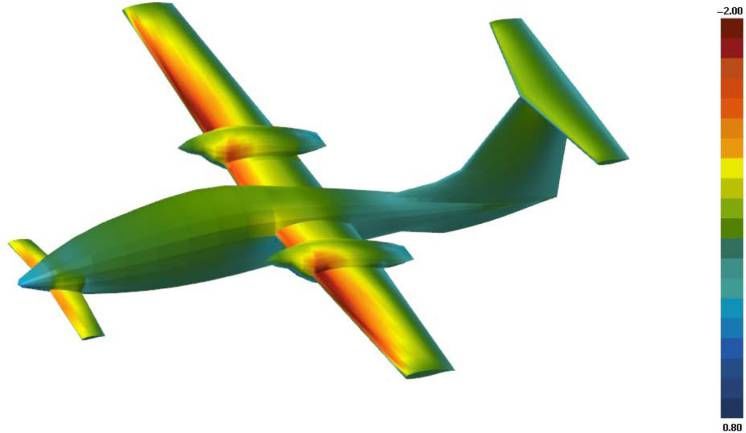
Three surface aircraft (TSA) configuration                        Aircraft Engineering and Aerospace Technology: An International Journal
                                                                             Tomasz Goetzendorf-Grabowski and Tomasz Antoniewski                                    Volume 88 · Number 2 · 2016 · 277–284

                                                                    Figure 5 Static margin versus airspeed                                          which corresponds with higher angle of attack. Second, an
                                                                                                                                                    essential lateral mode of motion is the spiral mode. This mode is
                                                                                                                                                    stable in whole airspeed range, which is presented in Figure 7.
                                                                                                                                                       The results of stability analysis of the first version of
                                                                                                                                                    presented aircraft were not satisfying. Both longitudinal and
                                                                                                                                                    lateral characteristics had to be improved. Longitudinal
                                                                                                                                                    stability was improved by changing the internal layout of
                                                                                                                                                    the aircraft and by rearranging the weights’ breakdown. The
                                                                                                                                                    lateral stability required the change of the shape of the
                                                                                                                                                    configuration. Usually, the dihedral angle reduces the Dutch
                                                                                                                                                    roll and the vertical tail increases the directional stability,
                                                                                                                                                    while the spiral mode can be worse, so the combination of
                                                                                                                                                    change of the dihedral and vertical stabilizer was applied. The
                                                                                                                                                    lateral stability was finally improved by decreasing the dihedral
                                                                                                                                                    angle to zero and moving the main wing up, to perform the
                                                                                                                                                    same position of engines (Figure 8). It improved the Dutch
                                                                                                                                                    roll and allowed to decrease the vertical tail area. The spiral
                                                                                                                                                    mode has still satisfying characteristics. Moreover, the results
Downloaded by POLITECHNIKA WARSZAWSKA At 02:32 15 March 2016 (PT)

                                                                                                                                                    of aerodynamic analysis showed that such changes are
                                                                                                                                                    advantageous       from      aerodynamics      point   of   view
                                                                    canard flap deflected to 15°) and landing (main wing Fowler                     (Mazurkiewicz, 2014). The flow around engine nacelles
                                                                    flaps deflected to 35° and canard flap deflected to 30°).                       appeared more clean, which resulted in reducing the drag.
                                                                       The aircraft configuration, especially a major part of the                   The final configuration is presented in Figure 9.
                                                                    fuselage in front of the main wing and a big dihedral angle of                     New configuration was tested. Three aerodynamic
                                                                    the main wing, is the reason why particular attention must be                   configurations were considered: clean, take-off (flaps 15°) and
                                                                    paid to the lateral stability.                                                  landing (flaps 30°). The aerodynamic characteristics were
                                                                       The basic factor of directional static stability, i.e. derivative of         obtained using panel methods (Figure 10). All modes of
                                                                    yawing moment with respect to sideslip angle, is positive, which                motion were checked, taking into account requirements from
                                                                    means that the aircraft is statically stable. However, the dynamic              airworthiness regulation for handling qualities.
                                                                    analysis shows that the characteristics of the most important,
                                                                    from flying qualities point of view, lateral mode of motion, i.e.               Phugoid
                                                                    Dutch roll, may not be satisfying, and it can even be unstable for              The dominating state variable in the phugoid mode is the
                                                                    a higher angle of attack. Figure 6 shows the Dutch roll                         airspeed, and angle of attack is almost constant. The period is
                                                                    characteristics against the background of criteria defined by                   usually long and oscillations are well damped. The
                                                                    CS-23. This criterion is not satisfied for low value of airspeed,               airworthiness requirements are not strong (CS-23, European

                                                                    Figure 6 Dutch roll characteristics versus calibrated airspeed (CS-23.181 criterion) – primary version

                                                                                                                                              280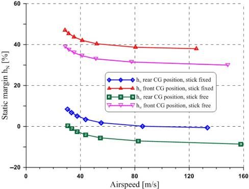
Three surface aircraft (TSA) configuration                 Aircraft Engineering and Aerospace Technology: An International Journal
                                                                            Tomasz Goetzendorf-Grabowski and Tomasz Antoniewski                              Volume 88 · Number 2 · 2016 · 277–284

                                                                    Figure 7 Time to double for spiral mode against to background of MIL-F-8785C criterion – primary version
Downloaded by POLITECHNIKA WARSZAWSKA At 02:32 15 March 2016 (PT)

                                                                    Figure 8 Changes in the configuration as the result of stability         Time needed to damp the amplitude to half is comparable
                                                                    analysis of the primary version                                          with the period and varies between 40 and 60 s.

                                                                                                                                             Short period
                                                                                                                                             The short-period oscillations connect rapid changes of angle
                                                                                                                                             of attack with the pitch rate. The period is usually very short.
                                                                                                                                             The requirements according to CS-23.181 say:
                                                                                                                                                Any short period oscillation not including combined lateral-directional
                                                                                                                                                oscillations occurring between the stalling speed and the maximum
                                                                                                                                                allowable speed appropriate to the configuration of the aeroplane must be
                                                                                                                                                heavily damped [. . .].

                                                                    Figure 9 AT-6 – final configuration                                      The results of computation show that short-period
                                                                                                                                             oscillations are well damped (Figure 12); however, for a
                                                                                                                                             clean configuration in case of the rear CG position,
                                                                                                                                             periodical character vanishes. Two non-periodical modes
                                                                                                                                             are stable.

                                                                                                                                             Dutch roll
                                                                                                                                             The Dutch roll requirements according to CS-23.181 are well
                                                                                                                                             defined:

                                                                                                                                             Figure 10 PANUKL computation: pressure distribution for
                                                                                                                                             AoA ⫺5° – final configuration

                                                                    Aviation Safety Agency, 2012): “Any long-period oscillation
                                                                    of the flight path (phugoid) must not be so unstable as to cause
                                                                    an unacceptable increase in pilot workload or otherwise
                                                                    endanger the aeroplane” (CS-23.181).
                                                                       The results obtained for AT-6 show (Figure 11) that
                                                                    phugoid is stable in the whole range of the CG position.

                                                                                                                                       281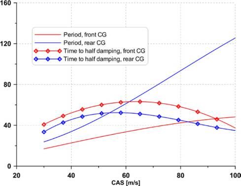
Three surface aircraft (TSA) configuration Aircraft Engineering and Aerospace Technology: An International Journal
Tomasz Goetzendorf-Grabowski and Tomasz Antoniewski Volume 88 · Number 2 · 2016 · 277–284
Figure 11 Phugoid – period and time to half damping versus Figure 13 Dutch roll characteristics versus calibrated airspeed
calibrated airspeed (CS-23.181 criterion)
Downloaded by POLITECHNIKA WARSZAWSKA At 02:32 15 March 2016 (PT)
Flight test
Figure 12 Short period oscillations – time to half damping versus
calibrated airspeed The unconventional configuration causes that there are many
unknowns despite the fact that advanced methods of
aerodynamic and stability analysis were applied. Thus, the 40
per cent scaled model was built and first flights were made in
late Spring 2014 (Figure 15). Test flights proved the expected
advantages of the configuration. Payload can be placed
from ⫺22 to 10 per cent of MAC (during tests even 13 per
cent was checked) and the longitudinal stability with fixed
stick is satisfied for each configuration (flaps, landing gear and
airspeed) and for full range of CG position. The small area of
canard has raised concerns due to its efficiency; however,
despite this, canard flaps are sufficient for a short takeoff, even
for the front CG position. The flight tests helped to determine
the optimal location of canard flaps due to the short takeoff for
the front CG position but also due to the reduction of the need
for pushing the stick in the landing configuration at the rear
CG position.
Releasing compartment cabin from the landing gear and
wings caused small cross sections giving better performance
which was a key parameter in the concept design. We also
obtained significantly higher lift coefficient (CL) for the whole
Any combined lateral-directional oscillations (”Dutch roll“) occurring
plane through participation of canard. Also, the extreme
between the stalling speed and the maximum allowable speed appropriate to
the configuration of the aeroplane must be damped to 1/10 amplitude in 7
angles of attack have been reached. For clean configuration,
cycles [. . .]. after conversion to a full-size aircraft, we expect CL about
1.65-1.7 and for Fowler flaps of 35° even CL ⫽ 2.4.
The obtained results show (Figure 13) that all configurations
Achieving high CL allowed to balance the surface of the
satisfy airworthiness requirements.
wings, so as to ensure a good cruising speed but low
minimum – only the combination of these two features will
determine the success of a commercial aircraft. Behavior in
Spiral mode
stall, especially in configuration with flaps, and with the engine
After improvement of the previous version, spiral is the only running is simply exemplary even at extreme rear CG position.
mode that is worse. However, airworthiness requirements are This is because the vortex wake from the canard is directed
not strong – CS-23-BOOK2: “[. . .] a slowacting mode called under the horizontal tail, by downwash from flaps and
the spiral which may be stable, but is often neutrally stable or engines. The clean configuration without an engine can
even mildly divergent in roll and yaw?”. Similar requirements dramatically roll the wing, but this is at extremely high angles
are seen in MIL-F-8785-C. Figure 14 shows the spiral mode of attack (18-20°), which is preceded by a strong vibration
time to double, which shows that spiral is unstable only for coming from the canard, whose role is to advance the stall,
small values of airspeed and time to double is sufficiently before stall on the main wing. The stall on the wing develops
big. from the nacelle and propagates to the inside and outside of
282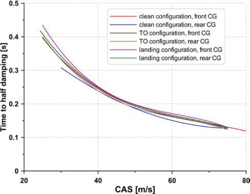
Three surface aircraft (TSA) configuration Aircraft Engineering and Aerospace Technology: An International Journal
Tomasz Goetzendorf-Grabowski and Tomasz Antoniewski Volume 88 · Number 2 · 2016 · 277–284
Figure 14 Time to double for spiral mode – clean configuration, front CG position
Downloaded by POLITECHNIKA WARSZAWSKA At 02:32 15 March 2016 (PT)
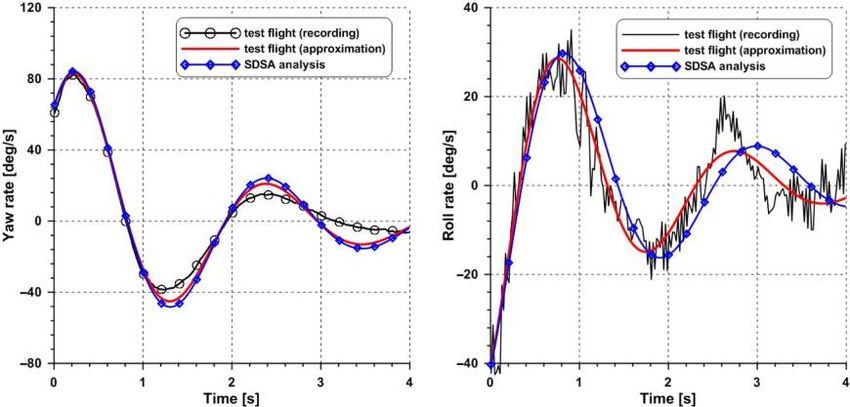
Figure 15 Test flight of 40 per cent scaled model during the first flights. Figure 16 shows recorded flight
parameters used for the Dutch roll rating and results of the
stability analysis made by SDSA (Goetzendorf-Grabowski
et al., 2011). Two parameters were taken into consideration –
roll rate and yaw rate. The Dutch roll was initiated by moving
the rudder in a doublet that reached the left and right stops.
Following this, the rudder was kept in the neutral. As it is seen
in Figure 16, the Dutch roll is stable and well damped. The
results are compliant with the results from numerical analysis.
Airspeed for numerical analysis was scaled according to
Froude number because calculations were made for full-scale
aircraft and flight test was performed for 40 per cent scaled
model.
Conclusion
According to the results of the flight tests of the scaled model,
which is dynamically similar, we can be optimistic for the
the wings, however, holding the aileron area free from stall, up
achievement of the objectives set for the full-size aircraft,
to angles of attack of 20°. Optimization of the position of the
namely:
engine nacelles was done during aerodynamic analysis ● cruising speed should be greater than 150 knots;
(Kubrynski, 2014; Mazurkiewicz, 2014). ● minimum airspeed, for configuration with flaps,
Test flights proved that the Dutch roll is stable and strongly
corresponds to an aircraft with bigger area (with the same
damped (Figure 16). Directional stability, which initially has
weight);
raised concerns due to the short arm of the vertical tail, is also ● “aerodynamic safety” is satisfied – stall, spin
very good. Spiral is not unstable. Moreover, interesting
characteristics, static and dynamic stability;
features occurred (but occurring in the classical configurations ● good visibility and comfort of cab; and
as well) – accelerated stall during turn generates a decrease in ● other performance and low operating costs resulting from
the lift force on the “faster” wing and ultimately it returns the
the aerodynamic (L/D over 15).
wings to level and prevents entering into a deep spiral or spin.
The spin must be strongly initiated, and depending on the The presented analysis focused on the flying qualities and
position of the CG, the first turn can also be a spiral. showed that all stability criteria defined in the airworthiness
Regardless of the number of turns, recovery followed regulations are satisfied. It is very important from the
immediately after the rudder deflection. certification point of view. The flight test results proved that
The Dutch roll is a mode of motion, which caused that numerical analysis is correct. The flight test must be repeated
some serious changes had to be done. Thus, it was tested for a full-scaled aircraft; however, current results bode
283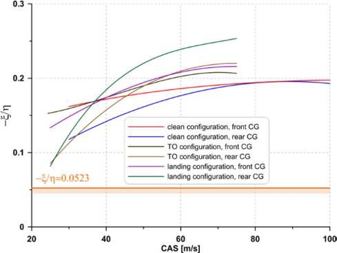
Three surface aircraft (TSA) configuration                       Aircraft Engineering and Aerospace Technology: An International Journal
                                                                             Tomasz Goetzendorf-Grabowski and Tomasz Antoniewski                                   Volume 88 · Number 2 · 2016 · 277–284

                                                                    Figure 16 Comparison of test flight and calculation results
Downloaded by POLITECHNIKA WARSZAWSKA At 02:32 15 March 2016 (PT)

                                                                    optimistic, especially, that criteria defined in MIL-F-8785C                   Kubryński, K. (1999), “Subsonic aerodynamic design via
                                                                    specification, which are usually stronger, are also satisfied.                   optimization”, in Fuji, K. and Dulikravich, G.S. (Eds),
                                                                                                                                                     Recent Development of Aerodynamic Design Methodologies -
                                                                    Further work                                                                     Inverse Design and Optimization, Vol. 68, Vieweg.
                                                                    Full-scaled aircraft is under development. All results from                    Kubryński, K. (2014), “Concept and aerodynamic design
                                                                    numerical analysis and test flights of scaled model will be                      of a three surface aircraft AT-6 (in Polish)”, Proceedings of
                                                                    taken into account. The first flight is expected in one year.                    XVI Conference on Mechanics in Aeronautics, Kazimierz
                                                                                                                                                     Dolny.
                                                                    References                                                                     Mazurkiewicz, Ł. (2014), “Numerical analysis of flow around
                                                                                                                                                     the airplane AT-6 (in Polish)”, Proceedings of XVI Conference
                                                                    Drela, M. (1989), “XFOIL: an analysis and design system for
                                                                                                                                                     on Mechanics in Aeronautics, Kazimierz Dolny.
                                                                      low Reynolds number airfoils”, in Mueller, T.J. (Ed.), Low
                                                                                                                                                   MIL-F-8785C (1980), “Military specification flying qualities
                                                                      Reynolds Number Aerodynamics, p. 54.
                                                                    Etkin, B. (1982), Dynamics of Flight - Stability and Control,                    of piloted airplanes”, 5 November.
                                                                      John Wiley & Sons, New York, NY.                                             PANUKL (2012), “Potential solver, software package”,
                                                                    European Aviation Safety Agency (2012), “Certification                           Warsaw University of Technology, available at: www.meil.
                                                                      specifications for normal, utility, aerobatic, and commuter                    pw.edu.pl/add/ADD/Teaching/Software/PANUKL
                                                                      category aeroplanes - CS-23”, Amendment 3.                                   Rizzi, A. (2011), “Modeling and simulating aircraft stability
                                                                    Galiński, C., Hajduk, J., Kalinowski, M., Wichulski, M. and                     and control-the SimSAC project”, Progress in Aerospace
                                                                      Stefanek, Ł. (2014), “Inverted joined wing scaled                              Sciences, Vol. 47 No. 8, pp. 573-588.
                                                                      demonstrator programme”, Proceedings of 29th Congress of                     Roskam, J. (2003), Airplane Flight Dynamics and Automatic
                                                                      the International Council of the Aeronautical Sciences.                        Flight Controls (Part I & Part II), DARcorporation.
                                                                    Goetzendorf-Grabowski, T. (2014), “Stability problems of
                                                                      three surface configuration”, Proceedings of 29th Congress of
                                                                      the International Council of the Aeronautical Sciences.                      Further reading
                                                                    Goetzendorf-Grabowski,          T.,   Mieszalski,     D.     and               ESDU, Royal Aeronautical Society (1954), ESDU
                                                                      Marcinkiewicz, E. (2011), “Stability analysis using SDSA                       (Engineering Sciences Data Unit), Aerodynamic Sub-Series,
                                                                      tool”, Progress in Aerospace Sciences, Vol. 47 No. 8,                          Royal Aeronautical Society, London.
                                                                      pp. 636-646.
                                                                    Goraj, Z. (2014), “Flight dynamics models used in different
                                                                                                                                                   Corresponding author
                                                                      national and international projects”, Aircraft Engineering and
                                                                      Aerospace Technology: An International Journal, Vol. 86                      Tomasz Goetzendorf-Grabowski can be contacted at:
                                                                      No. 3, pp. 166-178.                                                          tgrab@meil.pw.edu.pl

                                                                    For instructions on how to order reprints of this article, please visit our website:
                                                                    www.emeraldgrouppublishing.com/licensing/reprints.htm
                                                                    Or contact us for further details: permissions@emeraldinsight.com

                                                                                                                                             284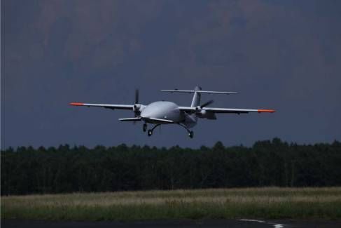
You can also read