Robust 3D Street-View Reconstruction using Sky Motion Estimation
←
→
Page content transcription
If your browser does not render page correctly, please read the page content below
Robust 3D Street-View Reconstruction using Sky Motion Estimation

                                             Taehee Lee
              Computer Science Department, University of California, Los Angeles, CA 90095
                                                     taehee@cs.ucla.edu

                         Abstract

    We introduce a robust 3D reconstruction system that uses
a combination of the structure-from-motion (SfM) filter and
the bundle adjustment. The local bundle adjustment pro-
vides an initial depth of a newly introduced feature to the
SfM filter, and the filter enables to predict the motion of the
camera while performing the reconstruction process. In ad-
dition, we increase the robustness of the rotation estimation
                                                                             (a) Omnidirectional camera image
by estimating the motion of the sky from cylindrical panora-
mas of street views. The sky region is segmented by a robust
estimating algorithm based on a translational motion model
in the cylindrical panoramas. We show that the combina-
tion of the SfM filter and the bundle adjustment with sky
motion estimation algorithms produces a robust 3D recon-
struction from the street view images, compared to running
each method separately.
                                                                               (b) Projective camera images

                                                                  Figure 1: Google Street-View dataset: (a) omnidirectional
1. Introduction                                                   camera image, (b) projective camera images of left, front,
   The 3D reconstruction problem is to recover the depth of       right and rear directions.
the scene structures from the 2D information in an image
or in multiple images. Especially when a camera is mov-
                                                                  that the large area of the streets in city blocks can be suc-
ing around the scene as taking photos or a video sequence,
                                                                  cessfully reconstructed. We introduce the 3D reconstruction
the problem is to estimate both of the structure of the scene
                                                                  algorithms that can be processed separately, and improve
and the motion of the camera at the same time. Estimating
                                                                  the robustness by proposing a combined method of those
the 3D scene structure and the camera motion is applicable
                                                                  algorithms and by estimating the camera’s rotation on the
in many areas: for examples, unmanned vehicles or robots
                                                                  ground using the motion of the sky.
can utilize the visual information in real-time so that they
                                                                     The rest of the paper is structured as follows: we first
can navigate through the scene or build a map of the place
                                                                  introduce the street-view image dataset and review the re-
while interacting with the environment. Moreover, many
                                                                  lated work on the 3D reconstruction problem in the follow-
recent internet-based map services provide not only two di-
                                                                  ing subsections. Next we explain our method of enhancing
mensional maps, but also the terrain or building models in
                                                                  the robustness of the 3D reconstruction in Section 2. Then
3D interactive interfaces. The image based modeling is also
                                                                  we show the experimental results and discuss in Section 3.
often used in computer graphics and filming industries.
                                                                  Finally, we conclude the paper and address the future work
   In this paper, we focus on reconstructing the 3D structure
                                                                  in Section 4.
of the streets in cities for assisting the vehicle navigation.
In order to generate the 3D map, the camera trajectory and
                                                                  1.1. Street-View Image Sequence
the structure are estimated using the image sequence taken
by a survey vehicle with a camera mounted on it. The re-             The images of street views are collected from a survey
construction algorithm requires to be accurate and robust so      vehicle that usually has a mounted camera or multiple cam-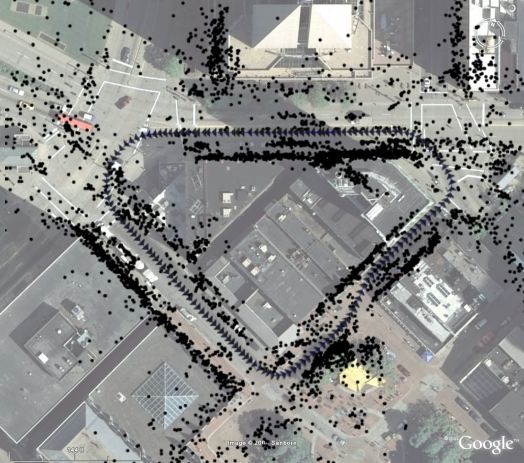
eras on the roof. When an omnidirectional camera is used,         some attention to the newly introduced features to the filter
for example in the Google Street-View dataset, the field of       without knowing their depths. In [1] the SfM filter manages
view of the camera is nearly spherical, covering 360◦ in          the features as a group when they are introduced. The filter
horizontal angles, and more than a hemisphere in vertical         then sets the group’s reference frame separately to the main
angles. Similarly, multiple cameras can be arranged so that       reference frame, and brings them into account only after
they cover the large field of view, as in [12].                   they are converged to an accurate depth estimation with a
    In this paper, we use the Google Street-View dataset that     threshold in the covariance.
is used to provide the Google Street-View service. The im-            In [3], a single monocular camera is used to capture im-
ages of streets are taken with an omnidirectional camera as       ages so that it can be worn by a person moving around the
in Figure 1a, and then projected into four rectangular image      scene. As targeting the real-time performance while track-
planes so that each of the image can be modeled as a projec-      ing the camera motion and building a map of the scene, they
tive camera as in Figure 1b. The images typically contain         use a few number of distinct image patches for their features
the sky, roads, side walls of buildings, and other objects as     and develop an extended Kalman filter to maintain and to
trees, cars, and pedestrians.                                     update the estimation of the feature locations and the cam-
    In most cases, the depths of these objects in the street-     era motion model. Since the reconstruction is kept in the
level views are significantly various in a large range, e.g.      state of a stochastic filter, the motion of the camera needs
the sky is extremely far away compared to nearby build-           to be well modeled by the motion dynamics. The system
ings. Moreover, the translation of the camera between con-        also requires to detect its unstable situations to prevent or
secutive frames is very small relatively to the farthest region   recover from the tracking failure cases.
in the image, i.e. the sky. From these observations, we need          On the other hand, there is another approach that does
to put more efforts on analyzing the street view images and       not use the Kalman filter but performs in similar scenarios
estimating the structure of the street scene. Additionally,       of a person interacting in small environments. In [6], corner
some part of the vehicle, for example the roof, is always         features are detected and matched in the selected keyframe
visible in all frames. In order to improve the robustness of      images from the real-time video sequence. The 3D location
the feature tracking and the 3D reconstruction algorithms,        of the features are estimated using the local bundle adjust-
we can rule out the stationary region by cropping the lower       ment and the global bundle adjustment in a multi-threaded
part of the image, or by using a mask image.                      system, while the camera motion is estimated in another
                                                                  thread running in real-time. Since this approach does not
1.2. Related Work                                                 require the camera motion to follow the dynamics model
   There have been many researchers investigating the 3D          as in the filter approach [3], the user can move more freely
reconstruction problem with different approaches. The re-         with wearing the camera as long as the system relocalize
construction algorithms are proposed and have been im-            the camera as described in [17] after losing the tracking and
proved according to their requirements in different tasks.        looking again at the scene that can be matched to the stored
For example, there is a strict constraint on real-time ap-        keyframes.
plications to complete the calculation within a given time            Without the purpose of running in the real-time appli-
constraint. On the other hand, some algorithms can spend          cation, there are other approaches that aim for reconstruct-
more time on modeling the 3D structure from a collection          ing larger areas of the scene. The bundle adjustment al-
of images without the strict real-time constraint, aiming for     gorithm is used for refining the camera parameters and the
more accurate and robust reconstructions. Based on their re-      feature parameters together using a non-linear optimiza-
quirements and capability on devices, some systems include        tion method [16]. The bundle adjustment is usually per-
more sophisticated and expensive sensors other than just a        formed at the final refinement step of the 3D reconstruction
camera, for example a global positioning system (GPS), an         as a global optimization problem, or it can run incremen-
inertial measurement unit (IMU), or a light detection and         tally as adding observations from new images over time as
ranging system (LIDAR).                                           in [6][15]. However, as the number of images increases, the
   The structure from motion (SfM) problem is to estimate         computation of each bundle adjustment takes longer time
the 3D structure of the scene and the motion of the camera        because of the increased problem size. In order to produce
as the camera moves in the scene. The observations in 2D          an initial estimation to the global refinement or to the SfM
image planes are the feature correspondences with the noise       filter, we can run the bundle adjustment locally within a
in measurements, e.g. the Gaussian noise. At every time           fixed time window, e.g. using the most recent Nlocal frames
moment as the estimation proceeds, the SfM filter as defined      that can be performed in the time constraint. In case of run-
in [1] predicts and updates its state variables that represent    ning the local bundle adjustment, the first Nf ixed frames are
the structure of the scene and the motion of the camera. As       set to be fixed so that they act as a reference frame while the
running the realization of the SfM filter, there must be paid     local optimization window slides over time.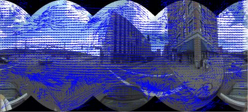
In [15] the images are collected from the internet to see
the scene location from different viewing angles and from
different cameras. The images are matched with each other
and sorted so that they produce a good track of feature cor-
respondences. Then the features from each image are pro-
cessed in order so that the 3D structure of the scene and the
camera locations are estimated using the incremental bundle
adjustment. Since this approach is to process the collection
of images in a batch process, the system takes more time
than the real-time applications as described earlier. The
resulting 3D reconstruction is used for the user to browse
through the virtual model of the scene and the photos that
are registered to the locations where they are taken from.
Moreover, the large-scale 3D reconstruction can be refined       Figure 2: Flowchart of combined procedures of the SfM
using the global bundle adjustment as in [10], where the 3D      filter and the bundle adjustment
map is divided into smaller submaps and their connections
are used for the global optimization.
    In the scope of building the 3D model of large areas such    features. Especially for the street-view images, the distribu-
as the streets in urban cities, a few systems have been devel-   tion of the depths of features in the field of view is not uni-
oped [2][12]. They collect the images of the locations using     form in general, caused by the commonly visible straight-
a survey vehicle that has a set of sensors including multiple    ahead roads and the side walls in deep perspective viewing
cameras, an omnidirectional cameras, and/or a GPS. In [2]        angles, for example. Therefore, here we introduce a method
two cameras are used in the stereo reconstruction pipeline,      of combining the SfM filter and the local bundle adjustment
running the local windowed bundle adjustment. Then the           in order to take the initial depth estimation of the new fea-
city model is generated as a textured model of the facades       tures from the bundle adjustment and to provide the infor-
of the buildings and the roads. Not only using the image         mation to the filter.
sequence, in [12] a GPS is used in order to estimate the             The procedure of running the SfM filter together with
camera motion and to prevent the estimation from drifting        the bundle adjustment is shown in Figure 2. For each image
over time. Then the depth map estimated from a stereo al-        captured from the video sequence, first we detect corner fea-
gorithm is refined and used for generating a 3D model of         tures [14] and track them using optical flows [7], or match
textured triangle meshes.                                        the features in case the features are revisited. At this step,
    Since the 3D reconstruction systems commonly use the         the prediction from the SfM filter can be used for restrict-
visual information from cameras entirely or partially, the       ing the camera motion at the feature tracking stage. The
task of enhancing the robustness and accuracy of the esti-       feature correspondences are then passed to the local bundle
mation is an important challenge. Thus we focus to improve       adjustment step. The local bundle adjustment uses a certain
the robustness of the vision-based reconstruction algorithms     number of previous frames as a fixed local reference frame,
in the rest of the paper.                                        and takes the initial estimations of the camera parameters
                                                                 and the depths of the new features using the linear methods
2. Method Description                                            as in [5]. The features are then passed to the SfM filter as
                                                                 observations, now with the initial estimation of the depths
   In this section, we propose our method of improving the       from the local bundle adjustment. The SfM filter updates its
robustness of the 3D reconstruction. First we explain how        states as same as it performs separately. And optionally, the
we can combine the procedures of the SfM filter and the          incremental bundle adjustment or the global bundle adjust-
bundle adjustment. Then the method of estimating the sky         ment can be performed in order to minimize the reprojec-
motion in cylindrical projection is introduced, followed by      tion error across the whole image sequence so far. As this
the method of estimating the rotation of the camera using        procedure goes on for each image, the SfM filter takes the
the motion of the sky. In the end, we describe how to select     initial depth estimation from the local bundle adjustment,
good quality feature for robust feature tracking and further     and provides the predictions of the camera motion to the
for maintaining the stable 3D reconstruction.                    feature tracking stage.

2.1. Combining SfM Filter and Bundle Adjustment                  2.2. Sky Motion Estimation
   Obviously the 3D reconstruction using the SfM filter can         When we define the sky as the region that is far apart
be improved with estimating the better initial depths of new     from the camera view point, the motion of the sky region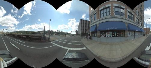
(a) Translation 1              (b) Translation 2

        (c) Rotation 1                   (d) Rotation 2
                                                                 Figure 4: The relationship of cylindrical projection coor-
Figure 3: Sky motion in cylindrical projection panoramas.        dinates (x, y) from the perspective projection coordinates
Camera moving forward (a),(b): When the camera trans-            (x0 , y0 ): (1) The top-down view shows the relationship on
lates without rotation, the sky does not move in the panora-     the x coordinates. The red arc from the Top-down view cor-
mas. Camera turning to the right (c),(d): When the camera        responds to the cylindrical projection image plane, and the
rotates on the ground along the vertical axis, the sky trans-    blue side of the rectangle is the perspective projection im-
lates horizontally.                                              age plane. (2) The side view shows the relationship on the
                                                                 y coordinates similarly.
is characterized differently than those of closer objects in
the scene. For example, the direction from a viewpoint on
the ground to a point in the sky is fixed under the assump-
tion that the sky is infinitely far away. Thus we model that
the points in the sky region is far away with respect to the
translation of the camera. We further approximate the sky
motion as a rigid translational model under the cylindrical
projection. As in Figure 3a-b, the sky stays still when the
camera translates without rotation. On the other hand, as in
Figure 3c-d, the sky translates horizontally when the camera                                 (a)
rotates along the vertical axis.
    First, cylindrical projection panoramas are generated
from the quadruple perspective projection images. Figure 4
illustrates the cylindrical projection from a rectangular pro-
jection image, in which the resulting cylindrical panorama
has a horizontal axis corresponding to the yaw angle, and
a vertical axis corresponding to the pitch angle. The cylin-
drical projection from the perspective projection image is
                                                                                             (b)
performed as below:
                         w                 π                 Figure 5: An example result of the sky segmentation: (a)
              x0 =           1 + tan x −                         dense optical flow computed from the cylindrical projection
                        2                  4
                                                                 panorama. (b) the result of sky segmentation is shown as
                               h        −1
                                                π h
              y0 =        y−        cos      x−     +            highlighted.
                               2                 4    2

     Icyl (x, y)   = Irect (x0 , y0 ),                    (1)
                                                                 between the frames, for example, using the Lucas-Kanade
where w and h are the width and the height of the perspec-       algorithm on image pyramids [7] as shown in Figure 5a.
tive projection image. This projection is performed for each     When we compute the optical flow from the cylindrical pro-
of quadruple images and concatenated to form a cylindrical       jection panoramas, we also need to crop the top and bottom
projection panorama.                                             of the image in order to avoid the aperture problem around
   In order to estimate the motion of the sky region between     the curved boundaries. Then we perform a robust sky seg-
two consecutive frames, we compute the dense optical flow        mentation algorithm using the RANSAC approach [4] to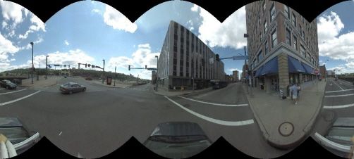
find the maximum number of pixels that satisfy a rigid            vehicles, the depths of the features in the image have wide
translation model: (1) randomly sample a pixel at every           range of distribution. In this case, limiting the maximum
iteration and collect other pixels as inliers that have simi-     depth of the features is a reasonable constraint in order to
lar optical flows within a threshold error, (2) and choose the    increase the numerical stability of the linear method solvers,
largest set of inliers as the sky region pixels. The sky motion   for example the singular value decomposition. In [8][5],
is then estimated as the mean of the optical flow from the        the importance of normalization is explained in the same
inlier pixels. In Figure 5b, the segmentation of sky region is    sense. Also the restricted depth range allows another outlier
highlighted in the cropped cylindrical projection panorama.       rejection mechanism so that the features with their depths
                                                                  less than a threshold are considered as inliers. After the
2.3. Rotation Estimation from Sky Motion                          feature tracking step, this constraint can still work for the
   After segmenting the sky region based on the transla-          local bundle adjustment stage as well. The features with
tional model in the cylindrical projection panoramas as in        too large depths or negative depths in the reference image
the previous section, the rotation parameter can be esti-         frame are rejected as outliers during the whole procedures.
mated from the motion of the sky. Especially as we model
the motion of the camera to be on the ground of the street,       3. Experimental Results
the sky motion in the cylindrical panoramas becomes a hor-
izontal translation. Thus the rotation parameter along the           We implemented the methods described in the previous
vertical axis can be estimated from the horizontal transla-       section and we experimented with the Google Street-View
tion of the sky. Given the cylindrical panorama with its          dataset images. In order to perform the 3D reconstruction
width W , the rotation on y-axis is computed as below:            algorithms using the SfM filter and the bundle adjustment,
                                                                  the images from the front camera are used. The calibration
                        θy = 2πdx /W ,                     (2)    matrix of the projective camera is known from the dataset,
                W W
where dx ∈ − 2 , 2 is the horizontal translation of the           and a manually labeled stationary mask image was used in
sky within the cylindrical panorama as computed from the          order to rule out the roof of the survey vehicle from the
optical flow in the previous section.                             reconstruction process. The performance of 3D reconstruc-
   Then the estimated rotation parameter θy can be used for       tion was compared between running the SfM filter and the
the SfM filter in the prediction of the camera motion, specif-    local bundle adjustment separately or combined. In addi-
ically for the rotation parameter along y-axis. The other two     tion, the rotation parameter was estimated from the sky mo-
components of the rotation can be predicted as the standard       tion estimation in cylindrical panoramas and it was tested
prediction of the SfM filter. The further steps of predict-       with the SfM filter prediction step to check if it helps the
ing the camera motion is performed as the SfM filter works        3D reconstruction to be more robust.
naturally.                                                           The image sequence from the Google dataset was taken
                                                                  to have 350 frames, which involves a few rotations and
2.4. Quality Feature Selection                                    makes a loop around a block of buildings. In Figure 7i, the
                                                                  camera trajectory from the GPS is overlayed on the satellite
   As shown in Figure 2, the feature correspondences re-          view of the street location.
sulted from the feature tracking procedure are passed to the
further steps in the 3D reconstruction, both to the local bun-    3.1. Rotation Estimation from Sky
dle adjustment and to the SfM filter. In order to increase
the robustness of the estimation algorithms in each step, ef-         First we experimented the rotation parameter estimation
forts must be put into every possible stages. For example,        from the sky motion estimation. In Figure 6a, the rota-
the tracked features between two frames must satisfy some         tion on vertical-axis θy was estimated between consecutive
constraints based on the assumptions on the scene, or on          frames using the sky motion, and plotted together with the
the camera motion. When we assume that the scene is not           ground truth rotations. As seen in the figure, the estimation
moving, then the features on moving objects as pedestrians        from the sky is accurate enough to be used as an initial rota-
or cars must be rejected as outliers. This outlier rejection      tion estimation for further 3D reconstruction steps. In Fig-
is commonly performed as applying the epipolar geome-             ure 6b, the histogram of the estimation error is displayed,
try constraint between the two frames, or among the three         of which mean is near zero and the standard deviation is
recent frames [8][5]. In addition to the epipolar geometry        0.0088 radian.
constraint, the predicted camera motion can be used in or-            As shown in the result, the sky motion gives a good ini-
der to set the expected locations of the features in the image    tial rotation parameter estimation of the camera. Especially
plane.                                                            when there is not enough number of features in the street
   Especially with the forward motion of the camera, which        structure, the sky motion plays a bigger role as estimating
is very common in the image sequence taken from survey            the rotation better than relying on few number of tracked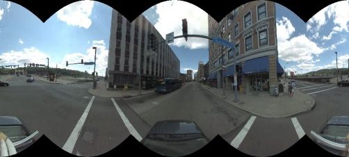
(a) Rotation estimation over time                         (b) Histogram of the estimation error

Figure 6: The rotation between two frames (in radian) is estimated over 350 frames using the Sky motion estimation: (a)
The thin red line is the ground truth rotation on y-axis, and the thick blue line is the rotation estimated from the sky motion.
(b) The histogram of the estimation error = θy − θtrue shows that the distribution is zero mean with the standard deviation
0.0088 radian.

features. The estimated rotation is then tested for improv-       for every 50 frames. The results from the LBA and IncrBA
ing the robustness of the 3D reconstruction in the following      show that overall estimation is more accurate than running
experiments.                                                      the SfM filter alone, but the rotation and the scale estima-
                                                                  tions are drifted from the true values as the errors are accu-
3.2. Comparisons of Trajectory Estimation                         mulated.
                                                                      Then the SfM filter was tested with the rotation estima-
    We tested the SfM filter and the bundle adjustment algo-
                                                                  tion from the sky motion estimation, shown in Figure 7d.
rithms on the same image sequence by combining them in
                                                                  Although the result shows that the filter adapted the rota-
a several different ways. In Figure 7, the results from these
                                                                  tion estimation well, the scale drifts over the frames. Next,
tests are displayed. In each plot, the thin red line is the
                                                                  the SfM filter was combined together with the LBA (see
ground truth trajectory from the GPS information, and the
                                                                  Figure 7e) and the IncrBA (see Figure 7f). In these tests the
thick blue line is the estimated trajectory from each method.
                                                                  initial depths of features are estimated from the bundle ad-
The estimated trajectories were aligned to the GPS trajec-
                                                                  justment algorithms and passed to the SfM filter. Although
tory so that the differences of the methods can be compared
                                                                  the camera motion was estimated more accurately, in both
correctly. In Figure 7i, the ground truth GPS trajectory is
                                                                  examples the rotation estimation was not robust enough so
overlayed on top of the satellite image of the location. For
                                                                  that the trajectory is rotated away from the ground truth.
these tests, the features were tracked only frame by frame
                                                                      Finally, the rotation parameter was estimated initially
and there was no relocalization method used so that the re-
                                                                  from the sky motion estimation, and it was used in the pre-
sult only shows how well each algorithm performs in terms
                                                                  diction step of the SfM filter. The estimated trajectory using
of the accuracy and the robustness without drifting away
                                                                  the SfM filter with the LBA together with the sky motion es-
from the true trajectory.
                                                                  timation is shown in Figure 7g. And the result of running
    To begin with, the SfM filter was tested alone as shown in
                                                                  the methods together is shown in Figure 7h. The results
Figure 7a, without the initial depth estimation of new fea-
                                                                  show that they outperform other methods in terms of the ro-
tures or the rotation estimation from the sky motion. Be-
                                                                  bustness of the reconstruction, and that the trajectories are
cause of the non-uniform distribution of the depths of the
                                                                  more accurate over the sequence. Among all experiments,
features in the scene, right after the vehicle starts to turn
                                                                  the combination of the SfM filter and the bundle adjust-
around the first corner the SfM filter begins to diverge from
                                                                  ments with sky motion estimation produces the most robust
the true path.
                                                                  reconstruction from the street-view images, as in Figure 7h.
    Next, the bundle adjustment was tested by running alone
the local bundle adjustment (LBA) (see Figure 7b), or
                                                                  3.3. Reconstructed 3D Structure
with the incremental bundle adjustment (IncrBA) (see Fig-
ure 7c). The LBA used 50 frames for the local windowed               In addition to the camera trajectory estimation, the 3D
optimization, and the IncrBA was performed periodically           structure of the scenes from the street-view images are re-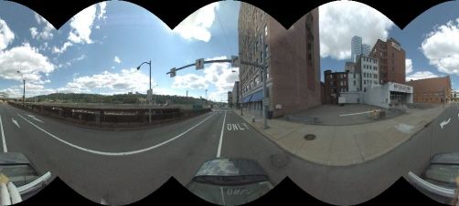
(a) Filter Only (b) Local BA Only (c) Local BA + Incremental BA
(d) Filter + Sky (e) Filter + LBA (f) Filter + LBA + IncrBA
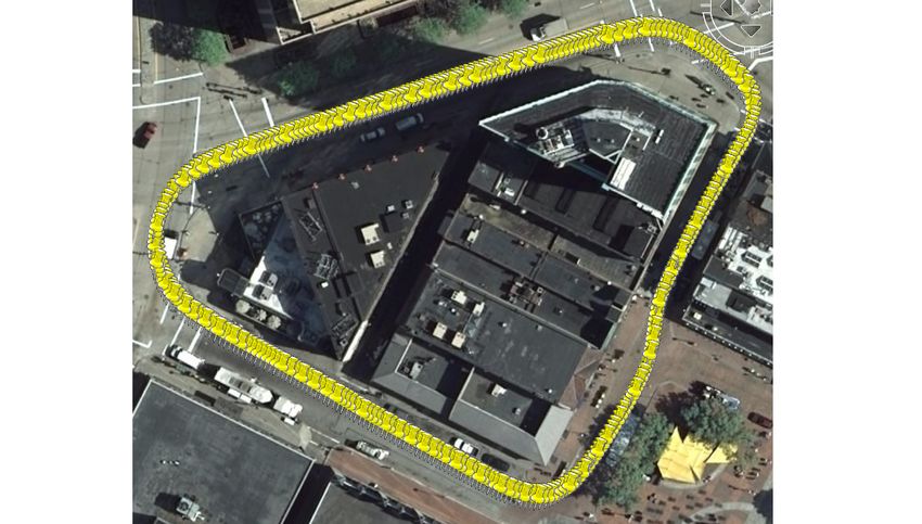
(g) Filter + Sky + LBA (h) Filter + Sky + LBA + IncrBA (i) GPS
Figure 7: The result of running different algorithms for the 3D reconstruction: (a) only the SfM filter, (b) only the local
bundle adjustment (LBA), (c) LBA with the incremental bundle adjustment (IncrBA), (d) using the sky motion estimation
with the SfM filter, (e) combining the SfM filter with LBA, (f) combining the SfM filter with LBA and IncrBA, (g) using
the sky motion estimation with the SfM filter, combined with LBA, (h) using all methods together (the SfM filter with sky
motion estimation, LBA and IncrBA), and (i) the ground truth trajectory taken from the GPS information.
constructed as a 3D point cloud. In Figure 8, the top view makes a loop clearly. When the relocalization algorithm
and the side view of the reconstructed point cloud are dis- as [17] or the location recognition algorithm as [13][11] is
played together with the camera trajectory. Figure 8a shows used in further, the revisited features can be used again so
the reconstructed points along the camera trajectory, and that the accumulated error over the past frames can be prop-
Figure 8b shows the satellite view image of the street lo- agated throughout the whole image sequence appropriately,
cation together in order to assist visual understanding. The recovering from the drift.
features are frequently detected on the walls of buildings In case that a more sophisticated 3D model is required,
accurately as shown in the overlayed image. Moreover, a triangulated mesh structure and a textured model can be
the point cloud of the reconstructed street scene shows the created from the reconstructed 3D point cloud and the im-
ground plane of the roads and the vertical walls of build- ages. Or, instead of using point features, superpixels can
ings clearly in the side view in Figure 8c. Some features be used for reconstructing planar structures as introduced
with noisy measurements still have inaccurate estimations in [9]. Other features as edges and planes can be used as
of their 3D locations. well to improve the quality of the reconstruction result.
Although no camera relocalization algorithm was used
4. Conclusion
in these experiments, the reconstructed camera trajectory
and the 3D point cloud show that the combination of the We introduced a robust 3D reconstruction system that
3D reconstruction algorithms described in the previous sec- combines the structure-from-motion filter with the local
tion produces an accurate estimation so that the trajectory bundle adjustment which initializes the depths of new fea-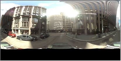
(a) Top-view                   (b) Top-view overlay                               (c) Side-view

Figure 8: The result of the 3D reconstruction from the street-view image sequence: (a) The top-view of the 3D point cloud
with the camera trajectory, (b) overlayed on the satellite image of the location (aligned manually), and (c) the side-view.

tures. Experimental results show that the proposed method            [7] B. Lucas and T. Kanade. An iterative image registration tech-
enhances the robustness of the 3D reconstruction from the                nique with an application to stereo vision. In Proc. Intl. Joint
street-view image sequence. In addition, the rotation pa-                Conference on Artificial Intelligence, pages 674–679, 1981.
rameter was estimated from the sky motion in cylindrical             [8] Y. Ma, S. Soatto, J. Kosecka, and S. Sastry. An invitation to
projection panoramas to estimate the camera trajectory and               3D vision, from images to models. Springer Verlag, 2003.
the 3D structure more robustly.                                      [9] B. Micusik and J. Kosecka. Multi-view superpixel stereo in
                                                                         man-made environments. Technical report, George Mason
   For future work, we are aiming to reconstruct larger area
                                                                         University, 2008.
of the streets in city blocks with an efficient relocalization
                                                                    [10] K. Ni, D. Steedly, and F. Dellaert. Out-of-core bundle ad-
algorithm in order to recover from accumulated errors over
                                                                         justment for large-scale 3d reconstruction. In Proc. IEEE
time. More investigation on fixing the scale drifting prob-              Intl. Conference on Computer Vision, pages 1–8, 2007.
lem is also necessary.                                              [11] D. Nister and H. Stewenius. Scalable recognition with a vo-
                                                                         cabulary tree. In Proc. IEEE Intl. Conference on Computer
Acknowledgment                                                           Vision and Pattern Recognition, volume 2, pages 2161–2168,
                                                                         2006.
   We would like to thank Google Research for providing             [12] M. Pollefeys, D. Nistér, J. M. Frahm, A. Akbarzadeh, P. Mor-
the Street-View dataset for the research.                                dohai, B. Clipp, C. Engels, D. Gallup, S. J. Kim, P. Mer-
                                                                         rell, C. Salmi, S. Sinha, B. Talton, L. Wang, Q. Yang,
                                                                         H. Stewénius, R. Yang, G. Welch, and H. Towles. Detailed
References                                                               real-time urban 3d reconstruction from video. Intl. Journal
 [1] A. Chiuso, P. Favaro, H. Jin, and S. Soatto. Structure from         of Computer Vision, 78(2-3):143–167, 2008.
     motion causally integrated over time. IEEE Trans. on Pattern   [13] G. Schindler, M. Brown, and R. Szeliski. City-scale location
     Analysis and Machine Intelligence, 24(4):523–535, 2002.             recognition. In Proc. IEEE Intl. Conference on Computer
 [2] N. Cornelis, K. Cornelis, and L. V. Gool. Fast compact city         Vision and Pattern Recognition, pages 1–7, 2007.
     modeling for navigation pre-visualization. Proc. IEEE Intl.    [14] J. Shi and C. Tomasi. Good features to track. In Proc. IEEE
     Conference on Computer Vision and Pattern Recognition,              Intl. Conference on Computer Vision and Pattern Recogni-
     2:1339–1344, 2006.                                                  tion, pages 593–600, 1994.
 [3] A. J. Davison, I. D. Reid, N. D. Molton, and O. Stasse.        [15] N. Snavely, S. M. Seitz, and R. Szeliski. Photo tourism: Ex-
     MonoSLAM: Real-time single camera SLAM. IEEE Trans.                 ploring photo collections in 3d. In SIGGRAPH Conference
     on Pattern Analysis and Machine Intelligence, 29(6):1052–           Proceedings, pages 835–846. ACM Press, 2006.
     1067, 2007.                                                    [16] B. Triggs, P. Mclauchlan, R. Hartley, and A. Fitzgibbon.
 [4] M. A. Fischler and R. C. Bolles. Random Sample Consen-              Bundle adjustment - a modern synthesis. In Vision Al-
     sus: A paradigm for model fitting with applications to im-          gorithms: Theory and Practice, LNCS, pages 298–375.
     age analysis and automated cartography. Commun. ACM,                Springer Verlag, 2000.
     24(6):381–395, 1981.                                           [17] B. Williams, G. Klein, and I. Reid. Real-time slam relocali-
 [5] R. Hartley and A. Zisserman. Multiple View Geometry in              sation. In Proc. IEEE Intl. Conference on Computer Vision,
     Computer Vision. Cambridge University Press, 2003.                  pages 1–8, 2007.
 [6] G. Klein and D. Murray. Parallel tracking and mapping for
     small AR workspaces. In Proc. IEEE/ACM Intl. Symposium
     on Mixed and Augmented Reality, pages 225–234, 2007.
You can also read