International Soap Box Derby, Inc - Super Stock Car Plans
←
→
Page content transcription
If your browser does not render page correctly, please read the page content below
International
    Soap Box Derby, Inc.

 Super Stock Car Plans

REVISED 02/13/14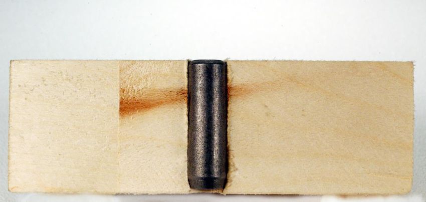
TABLE OF CONTENTS
Super Stock Division Program                                          Page 3
General Assembly Guidelines                                           Page 4
Help, Guidance & Support                                              Page 4
Supplies & Tools                                                      Page 5

Let's Get Started                   Floorboard Overview Legend        Page 6
Step One                            Steering Stop Installation        Page 7
Step Two                            Foot Brace Installation           Page 8
Step Three                          Kingpin Installation              Page 9
Step Four                           Steering Hardware Installation    Page 13
Step Five                           Steering Cabling Installation     Page 16
Step Six                            Stabilizer Installation           Page 21
Step Seven                          Brake Pad Installation            Page 25
Step Eight                          Brake Installation                Page 26
Step Nine                           Weight Bolt Installation          Page 31
Step Ten                            Airfoil Installation              Page 33
Step Eleven                         Wheel Kit Installation            Page 35
Step Twelve                         Shell Installation                Page 36
Step Thirteen                       Signage, Lettering & Decoration   Page 38
Step Fourteen                       Axle Alignment & Triangulation    Page 39
Step Fifteen                        Assembly Checklist                Page 40

Tech Tips
    E20 – Optional Weights                                            Page 42
    E21 – Optional Finishes                                           Page 45
    E22 – Cockpit Foam                                                Page 47
    E23 – Alignment                                                   Page 49
    E24 – Permitted Modifications                                     Page 51

Index                                                                 Page 52

REVISED 08/01/13                            SUPER STOCK                         2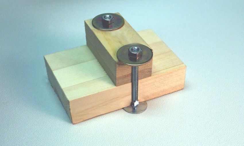
SUPER STOCK DIVISION PROGRAM Welcome to this exciting experience known as Soap Box Derby Racing! The International Soap Box Derby, Inc. program is designed to be an enjoyable learning experience for both the adult and the child. The program provides an opportunity to develop mutual respect and trust while demonstrating the importance of individual pride and sportsmanship. The Super Stock car is a sit-up car designed to be driven in a lean forward position at all times for builders of a specific age range. The combined weight of the assembled car and the driver shall not exceed 240 pounds including the Z-Glas wheels. A combined weight of less than 240 pounds may be increased by the addition of owner provided weight. The written rules, plans and regulations are designed for the participant to construct the car from a Super Stock Car Kit purchased from the International Soap Box Derby, Inc. For rules and regulations, including eligibility and age range information, see the “Rule Book” available from the International Soap Box Derby, Inc. at www.aasbd.org/about-us/rule-book-.aspx. The established rules, plans and regulations shall be applicable to all races and events and shall be taken into account as to all issues involving the construction of a car. By participating in these events, all participants are deemed to have consented to the rules and authority of person who shall enforce the rules. No expressed or implied warranties of any kind, including any warranty of safety, shall result from the publication or compliance with these rules, plans and regulations. In no event shall the International Soap Box Derby, Inc. be liable for any loss, indirect, special or consequential damages even if the International Soap Box Derby Inc. has notice of possibility of such damages. The International Soap Box Derby, Inc. makes no warranties, including any warranties of fitness for a particular purpose with respect to the publication or compliance with these rules, plans or regulations. In all situations, the rules and regulations promulgated by the International Soap Box Derby, Inc. shall govern and control over any conflicting provision in these plans. Each participant understands and agrees that a prerequisite to competing in any Championship Race sanctioned by the International Soap Box Derby Inc. in Akron, Ohio, that the racer and his or her car shall undergo and pass inspection conducted at Akron, Ohio by the International Soap Box Derby Inc. Each participant further understands and agrees that such inspection shall be conducted using the manner and methods deemed appropriate by the International Soap Box Derby Inc. in its sole discretion to determine compliance with the rules, plans, regulations, Spirit of the Rules and specifications applicable to that division and that the decisions of the International Soap Box Derby Inc. and its officials regarding qualifications and disqualification in compliance with the rules, Spirit, plans, regulations and specifications applicable to that division shall be final and binding upon all parties. REVISED 08/01/13 SUPER STOCK 3
GENERAL ASSEMBLY GUIDELINES
A parent, guardian or mentor is expected to help in the construction of the car. The parent, guardian
or mentor must not build the car for the child, but instead share this educational experience by being
present and giving help only when and if necessary.

This plan booklet shall be followed when assembling your car. The hardware provided in the
International Soap Box Derby, Inc. Super Stock Car Kit must be used and assembled as shown in the
latest rules, plans and specifications. No changes, modifications or additions, other than the inclusion
or omission of specified optional parts, shall be made to the car. All new and existing cars shall be
updated to the latest set of rules and plans for the Super Stock division.

In the event there is any conflict between the written portions of this plan booklet and the pictures or
diagrams, the written portions in all situations will control.

Replacement of all hardware, as well as optional parts, is available from the International Soap Box
Derby, Inc. In general, replacement parts are sold in bags specified for each installation step of the
car’s construction and optional parts are available on a per item basis.

                     HELP, GUIDANCE & SUPPORT
Questions or inquiries for clarification pertaining to the rules, plans and/or regulations shall be
directed primarily to your Local Race Director and/or Regional Director. The International Soap Box
Derby, Inc. also offers a web site at www.aasbd.org that provides additional assistance to the parent,
guardian, mentor and/or child. The website contains links to useful information such as the latest
rules and plans, ordering kits or parts online, Local Race city Organization contact information and
frequently asked questions to name a few. In addition, this website allows you to join the mailing list
to receive updates from the Derby Headquarters.

If further explanation is needed, questions should be directed to the International Soap Box Derby,
Inc. Racing Commission. All questions or inquiries for clarification must be emailed to
racingcommission@aasbd.org or requested in writing, including the full name and contact information
(address, phone number) of the participant, to:

                            International Soap Box Derby, Inc.
                            ATTN: Racing Commission
                            P.O. Box 7225
                            Akron, Ohio 44306

Please note that a response to a specific participant’s question may not apply to all other
participants.

REVISED 08/01/13                              SUPER STOCK                                                  4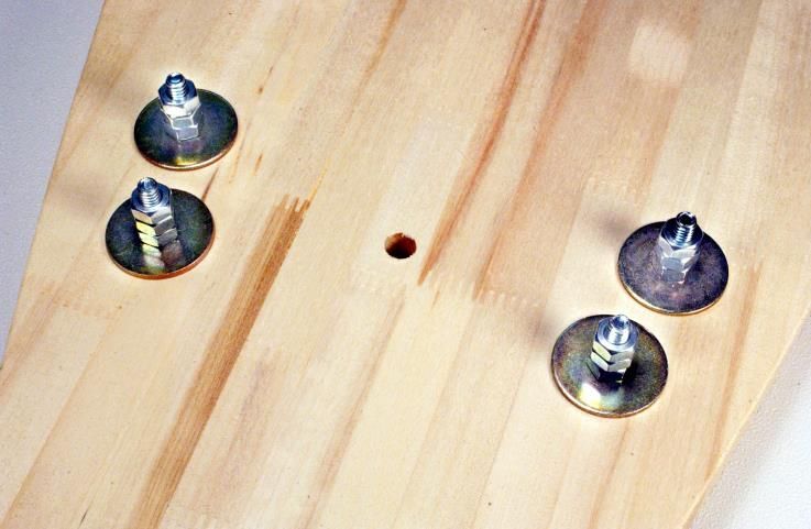
SUPPLIES & TOOLS
The following list of tools is a guideline to aid in the basic assembly of the Super Stock Car Kit. The
International Soap Box Derby, Inc. does not provide these tools as part of the kit. Sources for these
tools include, but are not limited to, hardware and automotive supply stores.
1. Screwdrivers 6. Hammer
- #2 Phillips screwdriver - Standard Hammer or Mallet
- Wide flat blade screwdriver
7. Soldering Iron with lead-free solder and
2. Wrenches or Sockets flux
- 3/8" open-end box wrench
- 7/16" open-end box wrench 8. Support Boards
- ½" open-end box wrench - (2) 2 x 4 x 18"
- 9/16" open-end box wrench
9. Triangulation Materials
3. Allen Wrenches
- 5/64" Allen Wrench 10. Feeler Gauges
4. Pliers 11. “C” Clamps
- Standard Pliers
- Wire Cutter Pliers 12. Battery Powered Drill
5. Measuring Tape
- 10’ minimum length
The following list of tools or supplies is a guideline to aid in the basic finish of the Super Stock Car
Kit. The International Soap Box Derby, Inc. does not provide these tools or supplies as part of the
kit. Sources for these tools include, but are not limited to, hardware and automotive supply stores.
1. Metal Cleaning Materials 3. Tape
- Steel wool - Electrical Tape
- Non-metallic abrasive pad - Clear Tape
2. Adhesive 4. Finishing
- Contact Cement - Automotive wax
- Paint (See Tech Tips on Optional
Finishes)
REVISED 08/01/13 SUPER STOCK 5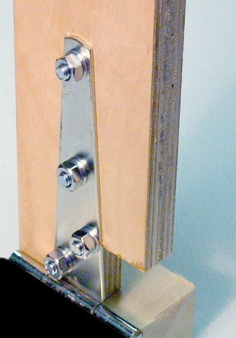
LET’S GET STARTED!
  This is the Super Stock Floorboard Legend. This diagram will give you a brief overview of some of the
  steps in the assembly process. Each step listed on this page will be explored in greater detail in
  upcoming steps.
                                                 FRONT                    SHELL HOLE “A”
                                                                         STEP #1: STEERING STOPS

                       STEP #3: KINGPIN
                                                                         STEP #9: WEIGHT BOLT
        STEP #2: FOOT BRACE

              STEP #4: STEERING                                         STEP #8: BRAKE PEDAL
                     HARDWARE
        DERBY LOGO AND DATE
        ON TOP SIDE OF BOARD                       *                     STEP #8: BRAKE KIT

                                                                          STEP #5: STEERING
                                                                          PULLEY
                     OPTIONAL WEIGHT
                     BOLT HOLES                                          STEP #8: BRAKE AWNING
                     (SEE TECH TIPS ON                                   PULLEY
                     OPTIONAL WEIGHTS)

              STEP #9: WEIGHT BOLT

STEP #6: SUPER STOCK STABILIZER

                        STEP #3: KINGPIN

                                                  REAR

               SUPER STOCK FLOORBOARD LEGEND

  REVISED 08/01/13                            SUPER STOCK                                             6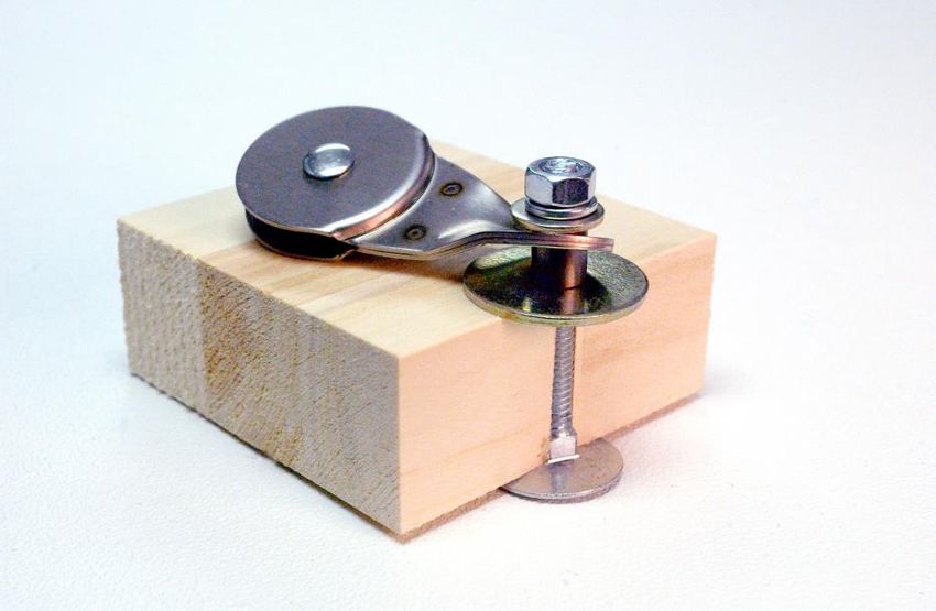
STEP ONE
Steering Stop Installation
Required items: Steering Stop Bag, Floorboard, Tools

                   ¼" x 1-¼"

                                                            Steering Stop
                   FENDER                              (Legend area highlighted)
                   WASHER
                                                    Steering Stop Installation
                                       1.1 Insert one ¼" x 2-¼" elevator bolt through the
                                           floorboard bottom at a steering stop hole location
                   ¼" NUT                  and press through the floorboard. See legend for
                                           location of holes.

                                       1.2 Place a ¼" x 1-¼" fender washer on the elevator
    ¼" x 2-¼" ELEVATOR BOLT                bolt on top of the floorboard.

                                       1.3 Install ¼" nut on ¼" x 1-¼" fender washer. Tighten
        HARDWARE SHOWN AT                  nut until elevator bolt is drawn in flush with bottom
            ACTUAL SIZE                    of floorboard. Install two additional ¼" nuts for a
                                           total of three. See Photo # 1.3

                                       1.4 Repeat Steps 1.1 through 1.3 for the other three
                                           steering stop locations. See Photo # 1.4

  ¼" x 1-¼"                    (3) ¼" NUTS
  FENDER
  WASHER

                               ¼" x 2-¼"
                               ELEVATOR
                               BOLT

Photo # 1.3                                   Photo # 1.4

REVISED 08/01/13                      SUPER STOCK                                               7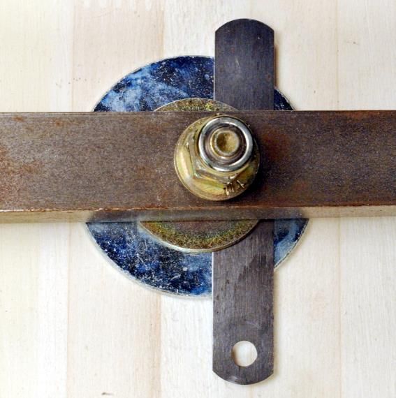
STEP TWO
Foot Brace Installation
Required Items: Foot Brace Bag, Floorboard, Foot Brace, Tools

                              ¼" x 3" ELEVATOR BOLT
        ¼" x 1-¼"                                                          Foot Brace
                                                                     (Legend area highlighted)

        FENDER                                                      Foot Brace Installation
        WASHER
                                                                       *See Tech Tip E24.3
                                                       2.1 Insert one ¼" x 3" elevator bolt through the
                                                           floorboard bottom at a foot brace hole location and
                                                           press through the floorboard. See floorboard
                                                           legend for location of holes.
        ¼" NUT
                                                       2.2 Place foot brace on the ¼" x 3" elevator bolt.

                                                       2.3 Place a ¼" x 1-¼" fender washer on the ¼" x 3"
                                                           elevator bolt on top of the foot brace.
         HARDWARE SHOWN AT                             2.4 Install ¼" nut on ¼" x 1-¼" fender washer.
             ACTUAL SIZE                                   See Photo # 2.4

                                                       2.5 Repeat Steps 2.1 through 2.4 for the second foot
                                                           brace bolt location.

                                                       2.6 Tighten nuts until elevator bolts are drawn flush
                                                           with bottom of the floorboard.

                     ¼" x 1-¼"                                               ¼" NUT
                     FENDER
                     WASHER

                     FOOT
                     BRACE

                                                                            ¼" x 3"
                                                                            ELEVATOR
                                                                            BOLT

                    Photo # 2.4
REVISED 08/01/13                                      SUPER STOCK                                              8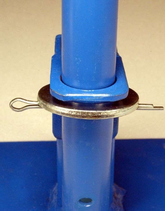
STEP THREE
Kingpin Installation
Required Items: Kingpin Bag, Floorboard, Set of Axles, SS Rear Axle
Plate, Tools
¼" x 3-¼" KINGPIN (GOLD IN COLOR)
¼" x 3-¼" MACHINE BOLT
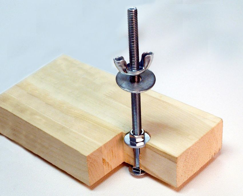
Bushing Installation
¼" FLAT (Legend area highlighted)
WASHER
Bushing Installation Sub-Assembly
*See Tech Tip E24.1
¼" NUT
3.1 Place ¼" x 1-¼" fender washer on ¼" x 3-¼"
machine bolt. Bolt is silver in color.
3.2 Place bushing with flat end against fender
washer on the ¼" x 3-¼" machine bolt.
3.3 Insert assembly through the top of floorboard
until bolt extends through opposite side of
¼" NylockTM NUT floorboard at kingpin location. See legend for
(KINGPIN NUT) location of holes
3.4 Place a ¼" x 1-¼" fender washer on the
machine bolt against the floorboard.
3.5 Install a ¼" nut on the ¼" x 1-¼" fender washer.
See Photo # 3.5
¼" x 2"
TOP OF FLOORBOARD
FLAT WASHER
¼” X 1-1/4”
FENDER WASHER
3/8” BUSHING
BUSHINGBUSHI
¼" x 1-¼" NG
¼” NUT
¼” x 1-1/4” FENDER
FENDER WASHER
WASHER
3 /8 "
BUSHING ¼” X 3-1/4” MACHINE
SCREW
HARDWARE SHOWN AT
REVISED 08/01/13 ACTUAL
SIZE SUPER STOCK PHOTO# 3.5 9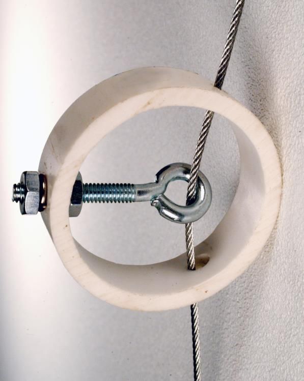
All floorboards require an AASBD                          Bushing Installation
  branding or engraved shield.
                                                           Sub-Assembly Continued
  The following floorboard dimensions
  must be met.                                 3.6 Tighten machine bolt assembly until bushing ends
       1. Front kingpin dimension of               are flush with floorboard.
          5-13/16” is a maximum value
          measured from the front              3.7 Remove ¼" nut from ¼" x 3-¼" machine bolt and
          center of floorboard to the              ¼" x 1-¼" fender washers. See Photo # 3.7
          center of the front kingpin.
                                               3.8 Repeat steps 3.1 through 3.7 for second kingpin
        2. Wheel base is 63-3/8” +/- 1/16”         bushing location.
           from center of front kingpin to
           the center of the rear kingpin.     3.9 Save ¼" nut, ¼" x 3-¼" machine bolt and ¼" x
                                                   1-¼" fender washers for future use in Step Six.

                                               3.10 Epoxy may be used to secure the bushings in
                                                    the floorboard. The expected way is to coat
                                                    the inside of the hole in the floorboard with
                                                    epoxy and then install the bushing before the
                                                    epoxy dries.

                                               3.11 Floating of the bushing by drilling an
                                                    oversize hole and permitting the epoxy to
                                                    fill the void is not acceptable.

                                               TOP OF FLOORBOARD

                                                                BUSHING FLUSH
                                                               WITH FLOORBOARD

                   Photo # 3.7

REVISED 08/01/13                             SUPER STOCK                                             10
KINGPIN HOLE
Front Axle
KINGPIN HOLE
Rear Axle
Figure # 3.15
Kingpin Installation
(Legend area highlighted)
Front Kingpin Sub-Assembly
4 Place a ¼" x 2" flat washer on ¼" x 3-¼" kingpin.
Kingpin bolt is gold in color.
5 Insert kingpin/washer assembly through the
bottom of floorboard at front axle location and
press through floorboard. See legend for location
of hole.
6 Place ¼" x 2" flat washer on ¼" x 3-¼" kingpin.
7 Place ¼" x 1-¼" fender washer on ¼" x 2" flat
washer.
8 Place ¼" flat washer on ¼" x 1-¼" fender washer.
9 Place front axle on ¼" flat washer.
See Figure # 3.15 for front axle identification.
10 Place two ¼" flat washers on top of the axle.
¼” FLAT ¼” NylockTM
WASHERS NUTS 11 Install two ¼" NylockTM nuts (kingpin nuts).
Tighten kingpin assembly. See Photo # 3.17
¼” FLAT
WASHER
¼” x 2” ¼” x 1-¼”
FLAT FENDER
WASHERS WASHER
Photo # 3.17
(Front Kingpin Washer Stack)
REVISED 08/01/13 SUPER STOCK 11KINGPIN HOLE
Front Axle
KINGPIN HOLE
Rear Axle
Figure # 3.24
Kingpin Installation
KINGPIN
(Legend area highlighted)
Rear Kingpin Sub-Assembly
12 Place a ¼" x 2" flat washer on ¼" x 3-¼" kingpin.
Kingpin bolt is gold in color.
13 Insert kingpin/washer assembly through the
bottom of floorboard at rear axle location and
press through floorboard. See floorboard legend
Photo # 3.20 for location of hole.
(Bolts other than the kingpin are not
part of this step; they are shown for 14 Place SS Rear Axle Plate on ¼" x 3-¼” kingpin.
clarity only.) Align holes in SS Rear Axle Plate with those in the
floorboard. See Photo # 3.20
15 Place ¼” x 2” flat washer on ¼” x 3-¼“ kingpin
¼” FLAT ¼” NylockTM (on top of the SS Rear Axle Plate).
WASHERS NUT
16 Place ¼" x 1-¼" fender washer on ¼” x 2” flat
¼” FLAT washer.
WASHER
¼” x 2” ¼” x 1-¼” 17 Place ¼" flat washer on ¼" x 1-¼" fender washer.
FLAT FENDER
WASHERS WASHER 18 Place rear axle on ¼" flat washer.
See Figure # 3.24 for rear axle identification.
Photo # 3.26 19 Place two ¼" flat washers on top of the axle.
(Rear Kingpin Washer Stack)
20 Install one ¼" NylockTM nut (kingpin nut).
See Photo # 3.26 Do not completely tighten
kingpin assembly. Further adjustments to occur
in future Step Fourteen.
REVISED 08/01/13 SUPER STOCK 12STEP FOUR
Steering Hardware Installation
Required Items: Steering Bag, Floorboard, Brake/Steering Mount,
Steering Wheel, Tools
Brake/Steering Mount
(Legend area highlighted)
¼" x 2-¼" ELEVATOR BOLT
Brake/Steering Mount Sub-Assembly
*See Tech Tip E24.2
4.1 Insert a quarter or washer (provided by others)
into the recessed floorboard area where the
¼" x 2" ELEVATOR BOLT steering wheel shaft is to be installed.
See Photo # 4.1
4.2 Align brake/steering mount with square tube over
large hole drilled through floorboard and large
3/32" x 1-3/4" COTTER PIN
round hole over quarter recessed floorboard area.
See Photo # 4.2
¼" LOCK
WASHER
¼" NUT
CABLE
PULLEY Photo # 4.1
BRAKE/ FRONT
¼" FLAT STEERING
WASHER OF CAR
MOUNT
¾" I.D.
FLAT
WASHER
Photo # 4.2
(Bolts shown for alignment only)
HARDWARE SHOWN AT
ACTUAL SIZE
REVISED 08/01/13 SUPER STOCK 13Brake/Steering Mount
Sub-Assembly Continued
4.3 Insert one ¼" x 2" elevator bolt through the
floorboard bottom at front brake/steering mount
¼” NUT hole location and press through the floorboard.
See floorboard legend for location of holes.
¼” LOCK
WASHER
4.4 Place brake/steering mount on ¼" x 2" elevator
¼” FLAT bolt.
WASHER
4.5 Place ¼" flat washer on ¼" x 2" elevator bolt (on
top of brake/steering mount).
4.6 Place ¼" lock washer on ¼" flat washer.
Photo # 4.7 4.7 Install ¼" nut over ¼" lock washer.
See Photo # 4.7 Do not completely tighten nut.
FRONT 4.8 Repeat Steps 4.3 through 4.7 for second front
OF CAR brake/steering bolt location.
4.9 Insert one ¼" x 2-¼" elevator bolt through the
floorboard bottom at rear brake/steering mount
hole location and press through the floorboard.
4.10 Place ¼" flat washer on ¼" x 2-¼" elevator bolt
(on top of brake/steering mount).
4.11 Place cable pulley on ¼" flat washer.
Photo # 4.13(a)
4.12 Place ¼" lock washer on cable pulley.
FRONT
4.13 Install ¼" nut on ¼" lock washer.
OF CAR
See Photo # 4.13(a) & Photo # 4.13(b).
¼” NUT Do not completely tighten nut.
¼” LOCK
4.14 Repeat Steps 4.9 through 4.13 for second rear
WASHER
brake/steering bolt at cable pulley location.
CABLE
PULLEY 4.15 Tighten all four nuts until bolts are drawn in flush
with bottom of floorboard. Insert brake plunger
¼” FLAT through floorboard and brake/steering mount to
WASHER check for proper alignment.
(NOT SHOWN)
Photo # 4.13(b)
REVISED 08/01/13 SUPER STOCK 14Steering Wheel Sub-Assembly
4.16 Insert steering wheel shaft through the round
hole on the brake/steering mount.
4.17 Raise the steering wheel and slide the ¾" I.D. flat
washer on to the bottom of steering wheel shaft.
ROUND HOLE ON MOUNT 4.18 Push steering wheel down through
brake/steering mount hole until shaft rests on top
¾” I.D. of quarter or washer installed in Step 4.1.
FLAT
WASHER 4.19 Push ¾" I.D. flat washer up against the
brake/steering mount and insert 3/32" x 1-¾"
cotter-pin through the upper steering wheel shaft
hole. See Photo # 4.19
4.20 Bend end of cotter pin around steering wheel
shaft.
COTTER
PIN
Brake/Steering Mount
Brake/Steering mount may be moved forward only to
accommodate a driver
Photo # 4.19
REVISED 08/01/13 SUPER STOCK 15STEP FIVE
Steering Cabling Installation
Required Items: Steering Cable Bag (complete with Steering Cable
and Cable Adjuster), Floorboard, Steering Cable, Tools
¼" x 2-¼" ELEVATOR BOLT
Cable Pulley Sub-Assembly
(Legend area highlighted)
8-32 x 1-5/8" EYE BOLT
Cable Pulley Sub-Assembly
¼" CABLE CLAMP
10-24 x 2" EYE BOLT
#8 LOCK
WASHER 5.1 Insert one ¼" x 2-¼" elevator bolt through the
floorboard bottom at a steering cable pulley hole
location and press through the floorboard. See
#10 LOCK legend for location of holes.
WASHER
5.2 Place a ¼" x 1-¼" fender washer on
¼" x 2-¼" elevator bolt on top of the floorboard.
¼" LOCK
5.3 Place cable pulley on ¼" x 1-¼" fender washer.
WASHER
5.4 Place ¼" lock washer on cable pulley.
¼" NUT 5.5 Install ¼" nut on ¼“ lock washer.
See Photo # 5.5
5.6 Tighten nut until bolt is drawn flush with bottom
of floorboard.
10-24 NUT CABLE PULLEY
5.7 Repeat Steps 5.1 through 5.6 for second cable
pulley hole location.
¼" x 1-¼"
8-32 NUT
¼” NUT ¼” LOCK
WASHER
FENDER CABLE
WASHER PULLEY
¼” x 1-¼”
FENDER
WASHER
HARDWARE SHOWN AT
ACTUAL SIZE Photo # 5.5
REVISED 08/01/13 SUPER STOCK 16EYEBOLT HOLE
Figure # 5.9
Axle Eyebolt Sub-Assembly
FRONT 5.8 Install 10-24 nut on 10-24 x 2" eyebolt. Tighten
OF CAR the 10-24 nut to the end of threads on eye bolt.
5.9 Insert assembly through driver side of front axle
at eye bolt location. See Figure # 5.9
5.10 Place a #10 lock washer on 10-24 x 2" eyebolt.
5.11 Install 10-24 nut on eyebolt assembly.
5.12 Tighten eyebolt assembly. See Photo # 5.12
5.13 Repeat Steps 5.8 through 5.12 for second axle
eyebolt assembly.
Cable Adjuster Sub-Assembly
Photo # 5.12 5.14 Install 8-32 nut on 8-32 x 1-5/8" eyebolt.
5.15 Insert eyebolt through any of the three holes of
cable adjuster and push through.
5.16 Place a #8 lock washer on 8-32 x 1-5/8" eyebolt.
5.17 Install 8-32 nut on # 8 lock washer.
See Photo # 5.17
5.18 Do not completely tighten assembly. Further
adjustments to occur in Step Fourteen.
5.19 Repeat Steps 5.14 through 5.18 for second cable
adjuster assembly.
5.20 May use 10-24 or 8-32 eyebolts.
Photo # 5.17
REVISED 08/01/13 SUPER STOCK 17Steering Cable Sub-Assembly
5.21 Determine the center point of the steering cable
by folding the cable in half.
5.22 Insert the two loose ends of the steering cable
through the lower hole of the steering wheel shaft
located horizontally above the floorboard.
5.23 Pull the two loose cable ends through the hole
until an eyelet is formed at the center point of
steering cable.
5.24 Wrap one loose end of cable around shaft 180
degrees and thread through eyelet.
See Figure # 5.23 Step one
5.25 Wrap other loose cable end in other direction
around shaft 180 degrees from first cable, and
thread through eyelet.
5.26 Pull both cable ends to tighten eyelet to secure
cable. Continue first cable around steering shaft
to a minimum of 360 degrees (at least one
complete wrap). See Figure # 5.26 Step two.
5.27 Center steering wheel and temporarily clamp
steering wheel from turning.
FACING REAR OF CAR
STEP ONE STEP TWO
(EYELET)
CENTER POINT
OF STEERING
LOWER HOLE CABLE
IN SIDE OF
STEERING
WHEEL SHAFT
STEERING
WHEEL SHAFT
STEERING
CABLE
180 Wrap 360 Wrap (or more)
Figure # 5.23 Figure # 5.26
REVISED 08/01/13 SUPER STOCK 18Steering Cable
Sub-Assembly Continued
Move eyebolt in 5.28 Thread one cable around steering pulley located
or out to adjust on brake/steering mount.
cable tension.
5.29 Thread this cable through the outside of one of
the two remaining holes in the cable adjuster and
into the inside of the cable adjuster.
5.30 Thread cable through eyebolt inside cable
adjuster.
5.31 Thread cable through the remaining hole in the
cable adjuster. See Photo # 5.31
5.32 Thread cable around cable pulley located on
floorboard.
5.33 Slide two ¼" cable clamps on cable end.
5.34 Thread cable through the front axle eyebolt
Photo # 5.31 assembly.
(Cable Adjuster Assembly)
5.35 Insert loose end of cable back through both
cable clamps.
5.36 Pull cables tight and tighten both cable clamps
with a 5/64" Allen Wrench. Cable clamps can be
placed next to each other. No space between
cable clamps is required. See Photo # 5.36
5.37 Cable can be double looped.
¼" CABLE CLAMPS
Photo # 5.36
REVISED 08/01/13 SUPER STOCK 19Steering Cable
Sub-Assembly Continued
5.38 Repeat Steps 5.28 through 5.36 for the other
cable. Refer to Photo # 5.37(a) & Photo
# 5.37(b) for cable route.
5.39 Adjust steering cables by adjusting 8-32 x 1-5/8"
eyebolts in cable adjuster assemblies.
5.40 Secure both cable adjusters by tightening both of
the 8-32 nuts. Cable adjusters may be located
anywhere along the cable in floorboard area
between pulleys. Remove temporary steering
FRONT wheel clamp from Step 5.27.
OF CAR
5.41 Test by turning steering wheel to the right while
seated facing the front of the car. The front axle
must turn to the right.
5.42 Excess steering cable may extend past second
¼" cable clamp and may be removed by cutting.
Photo # 5.37(a) To avoid cable fraying it is recommended that
solder be applied to a ¼" +/- on either side of the
proposed cut prior to cutting.
5.43 Steering cable adjustment to occur in future Step
Fourteen.
5.44 Steering wheel bowtie may face in either
direction.
FRONT
OF CAR
Photo # 5.37(b)
REVISED 08/01/13 SUPER STOCK 20STEP SIX
Stabilizer Installation
Required Items: Super Stock Stabilizer Bag, Angle Iron, Parts for
Bushing Installation from Step Three (¼" x 3-¼" machine bolt, ¼" nut
and two ¼" x 1-¼" fender washers), Tools
¼" x 2-½" ROUND HEAD BOLT
¼" x 2-¼" MACHINE BOLT
BOLTboltBOLT Stabilizer Installation
(Legend area highlighted)
Stabilizer Bushing Sub-Assembly
6.1 Rotate SS Rear Axle Plate installed in Step
Three away from stabilizer bolt holes.
See legend for location of holes.
6.2 Place ¼" x 1-¼" fender washer on ¼" x 3-¼"
machine bolt saved from Step Three.
¼" x 2”
BUSHING
6.3 Place bushing with flat end toward washer on
¼" x 2-¼" machine bolt.
FLAT WASHER
6.4 Insert machine bolt assembly through the top or
3 /8 "
bottom of floorboard with beveled end of bushing
against floorboard and press through floorboard
at stabilizer bolt location.
¼" NUT
¼" LOCK
WASHER
¼" x 1-¼"
FENDER
¼" FLAT WASHER
WASHER
HARDWARE SHOWN AT
ACTUAL SIZE
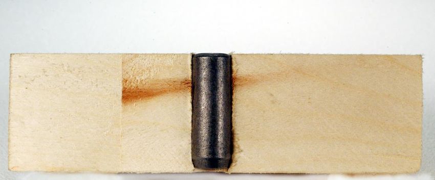
REVISED 08/01/13 SUPER STOCK 21TOP OF FLOORBOARD Stabilizer Bushing
Sub-Assembly Continued
¼” x 1-1/4” FENDER
WASHER 6.5 Place a ¼" x 1-¼" fender washer on ¼" x 3-¼"
machine bolt against bottom of floorboard.
3/8” BUSHING
6.6 Install ¼" nut on ¼" x 1-¼" fender washer.
See Photo # 6.6
¼” x 1-1/4” 6.7 Tighten machine bolt bushing assembly until
FENDER bushing end is flush with floorboard.
WASHER
¼” NUT
6.8 Remove ¼" nut, machine bolt and washers.
See Photo # 6.8
¼” X 3-1/4”
MACHINE BOLT 6.9 Repeat Steps 6.2 through 6.8 for second
stabilizer bushing location.
Photo # 6.6
6.10 Save ¼" nut, ¼" x 3-¼" machine bolt and two ¼"
x 1-¼" fender washers for possible future use.
6.11 Realign the SS Rear Axle Plate with the
stabilizer bolt holes.
6.12 Epoxy may be used to secure the bushings in
the floorboard. The expected way is to coat the
inside of the hole in the floorboard with epoxy
and then install the bushing before the epoxy
dries.
6.13 Floating of the bushing by drilling an
oversize hole and permitting the epoxy to fill
the void is not acceptable
TOP OF FLOORBOARD
BUSHING FLUSH
WITH FLOORBOARD
Photo # 6.8
REVISED 08/01/13 SUPER STOCK 22Stabilizer Bolt
Figure # 6.12 Kingpin
Rear Axle
Angle Iron
Sub-Assembly at Rear Axle
6.12 Insert ¼“ x 2-½“ round head bolt through back
side of rear axle at a stabilizer bolt hole location.
See Figure # 6.12 for stabilizer bolt hole
locations. Round head bolt should be tight to the
axle.
1" 6.13 Place a ¼“ lock washer on ¼“ x 2-½“ round head
bolt.
6.14 Install ¼“ nut on ¼“ lock washer. Tighten nut.
Photo # 6.18 6.15 Repeat Steps 6.12 through 6.14 for the second
stabilizer bolt hole.
6.16 Install a second ¼“ nut on ¼“ x 2-½“ round head
bolt leaving a 1“ +/- gap between the axle and
the second ¼“ nut.
6.17 Place a ¼" flat washer against the second
¼” nut.
BOTTOM LEG OF 6.18 Repeat Steps 6.16 and 6.17 for second stabilizer
ANGLE IRON bolt hole. See Photo # 6.18
Photo # 6.19 6.19 Slide the angle iron over the two bolts keeping
the bottom leg flat against the SS rear axle plate.
See Photo # 6.19
6.20 Place a ¼" flat washer on ¼“ x 2-½“ round head
bolt.
6.21 Place ¼“ lock washer on ¼" flat washer.
6.22 Install ¼“ nut on ¼“ lock washer. Do not
completely tighten. See Photo # 6.22
6.23 Repeat Steps 6.20 through 6.22 for second
Photo # 6.22 stabilizer bolt hole.
REVISED 08/01/13 SUPER STOCK 23Angle Iron Sub-Assembly
at Rear Axle Continued
6.24 The angle iron upright should be parallel with the
rear axle. By maintaining the 1” +/- gap, the
holes in the bottom leg of the angle iron should
be aligned with those in the SS rear axle
plate/floorboard.
1"
6.25 Tighten both sets of the ¼“ nut assemblies on
each side of the angle iron. See Photo # 6.25
Photo # 6.25
Angle Iron
Sub-Assembly at Floorboard
6.26 Place ¼“ x 2” flat washer on ¼“ x 2-¼“ machine
bolt.
6.27 Insert bolt assembly through the bottom of
floorboard at stabilizer/bushing location and
press through the floorboard, SS rear axle plate
and angle iron. See Photo # 6.27
6.28 Place ¼“ flat washer on ¼“ x 2-¼“ machine bolt.
Photo # 6.27
6.29 Place ¼“ lock washer on ¼" flat washer.
6.30 Install ¼“ nut on ¼“ lock washer.
See Photo # 6.30
6.31 Do not completely tighten. Further
adjustments to occur in future Step Fourteen.
6.32 Repeat Steps 6.26 through 6.31 above for
second stabilizer bolt hole.
Photo # 6.30
REVISED 08/01/13 SUPER STOCK 24STEP SEVEN
Brake Pad Installation
Required Items: Brake Pad Bag, Plunger, Tools
Brake Pad Installation
7.1 Insert one ¼" x ¾" flat head bolt through each
hole of the brake pad. Either side of the brake
pad may be used. See Photo # 7.1
¼" x ¾" 7.2 Align bolts in brake pad with holes in flat bottom
FLAT HEAD of the plunger and insert.
BOLT
WASHER 7.3 Place a ¼" lock nut (silver in color) on ¼" x ¾"
flat head bolt. See Photo # 7.3
¼" LOCK NUT
(SILVER IN COLOR)
7.4 Tighten assembly. It is recommended that
approximately an eighth of the ¼" x ¾" flat head
bolt (or three threads) is exposed. The ¼" x ¾"
HARDWARE SHOWN AT flat head bolt will be recessed in the bottom of
ACTUAL SIZE the brake pad. See Photo # 7.4
7.5 Repeat Steps 7.1 through 7.4 for other three bolt
Brake Pad Installation locations.
The brake pad may be installed to the There must be an eighth of
plunger using both a ¼” lock washer the ¼" x ¾" flat head bolt
and ¼” nut (provided by others) instead (or three threads) exposed.
of using the ¼” lock nut.
Photo # 7.4
(Brake Pad/Plunger Assembly)
Photo # 7.1
(Brake Pad)
REVISED 08/01/13 SUPER STOCK 25STEP EIGHT
Brake Installation
Required Items: Brake Bag, Floorboard, Brake Pad/Plunger Assembly
from Step Seven, Brake Spring, Tape (provided by others), Tools
¼" x 2-¼" ELEVATOR BOLT
Brake Pedal Hinge Sub-Assembly
8.1 Align the four hinge holes with the brake pedal.
¼" x 2-¼" EYE BOLT
Top of the wood brake pedal has rounded
¼" x 2" ELEVATOR BOLT corners and the bottom is straight. The fifth hole
located at the rounded corner is for brake pedal
eyebolt installation.
¼" x 1" MACHINE
¼" x 1-¼" FLAT
8.2 Insert ¼" x 1-¼" flat head bolt through brake
HEAD BOLT
pedal and through one of the four hinge holes.
8.3 Install ¼" lock washer on ¼" x 1-¼" flat head
BOLT
bolt.
8.4 Install ¼" nut on ¼" lock washer.
See Photo # 8.4 Do not completely tighten.
8.5 Repeat Steps 8.2 through 8.4 for other three
bolts.
¼" NUT ¼" LOCK CABLE
WASHER CLAMP 8.6 Tighten nuts until bolt heads are flush with face
of brake pedal.
¼" x 1-¼"
FENDER
WASHER
CABLE PULLEY
AWNING
PULLEY
¼" FLAT SPACER
WASHER
HARDWARE SHOWN AT
ACTUAL SIZE
Photo # 8.4
(Partial image shown for clarity)
REVISED 08/01/13 SUPER STOCK 26Brake Pedal Eyebolt Sub-Assembly
8.7 Install ¼" nut on ¼" x 2-¼" eyebolt. Tighten nut
to the end of threads on eyebolt.
8.8 Place ¼" x 1-¼" fender washer on the eyebolt.
8.9 Insert eyebolt assembly through the hole in the
wood brake pedal on side opposite hinge.
8.10 Place ¼" x 1-¼" fender washer on the brake
pedal eyebolt assembly.
8.11 Install ¼" lock washer on ¼" x 1-¼" fender
washer.
Photo # 8.12
(Eyebolt will face rear of car) 8.12 Install ¼" nut on ¼" lock washer.
See Photo # 8.12
8.13 Tighten eyebolt assembly.
Brake Assembly Installation
(Legend area highlighted)
Brake Pedal Hinge
Sub-Assembly at Floorboard
8.14 Align the two outer holes of the brake pedal
hinge with holes in floorboard at brake pedal
location (center hole of hinge not used).
See legend for location of holes.
8.15 Insert one ¼" x 2" elevator bolt through the
floorboard bottom at a brake pedal hole location
and press through the floorboard and brake
pedal hinge hole.
8.16 Place ¼" lock washer on ¼“ x 2” elevator bolt.
8.17 Install ¼" nut on ¼” lock washer.
Do not completely tighten.
8.18 Repeat Steps 8.14 through 8.17 for second bolt.
8.19 Tighten both nuts until bolts are drawn in flush
with bottom of floorboard. See Photo # 8.19
Photo # 8.19
Brake Pedal and Foot Brace
Brake pedal and foot brace may be moved forward or
back to accommodate a driver
REVISED 08/01/13 SUPER STOCK 27Cable Pulley Sub-Assembly at
¼" LOCK Brake/Steering Mount
WASHER
¼" NUT 8.20 Insert ¼" x 1" machine bolt through cable pulley.
8.21 Place ¼" flat washer on ¼" x 1" machine bolt.
8.22 Insert ¼" x 1" machine bolt with cable pulley and
flat washer through hole in the left side of the
vertical plate of the brake/steering mount.
¼" FLAT
WASHER 8.23 Place ¼" lock washer on the machine bolt
assembly.
Photo # 8.25
8.24 Install ¼" nut on ¼" lock washer.
8.25 Tighten assembly. Cable pulley shall spin freely.
See Photo # 8.25
Plunger Sub-Assembly
8.26 Install ¼" nut on ¼" x 2-¼" eyebolt. Tighten nut
to end of threads on eyebolt.
8.27 Insert square tube end of brake plunger
assembly through bottom of floorboard at large
round hole of brake/steering mount and push
Photo # 8.27
through top of brake/steering mount.
(Steering wheel and steering cables
not shown for clarity)
8.28 See Photo # 8.27
8.29 Place brake spring over brake plunger.
8.30 Compress brake spring coil and insert eyebolt
assembly through hole of plunger. (Eyebolt faces
rear of car).
8.31 Place ¼" lock washer on the eyebolt assembly.
REAR OF CAR
8.32 Install ¼" nut on ¼” lock washer.
See Photo # 8.31
8.33 Tighten eyebolt assembly.
8.34 Push assembly down several times to ensure
smooth operation.
Photo # 8.31
REVISED 08/01/13 SUPER STOCK 28Awning Pulley Installation
(Legend area highlighted)
Awning Pulley Sub-Assembly
8.35 Insert one ¼" x 2-¼" elevator bolt through the
floorboard bottom at awning pulley hole location.
See legend for location of hole.
8.36 Place ¼" x 1-¼" fender washer on the elevator
bolt on top of the floorboard.
8.37 Place spacer on ¼" x 1-¼" fender washer.
8.38 Place awning pulley hole on spacer.
8.39 Place ¼" flat washer on awning pulley.
8.40 Place ¼" lock washer on ¼" flat washer.
8.41 Install ¼" nut on ¼" lock washer.
8.42 The awning pulley swings freely and should be
pointed toward the front of the car.
See Photo # 8.41
8.43 Tighten nut until bolt is drawn flush with bottom
of floorboard.
AWNING ¼” NUT ¼” LOCK
PULLEY WASHER
¼” FLAT
WASHER
SPACER
¼” x 1-¼”
FENDER
WASHER
Photo # 8.41
REVISED 08/01/13 SUPER STOCK 29Brake Cable Sub-Assembly
Cable Clamps
8.44 Slide two cable clamps on one end of the brake
Brake and steering cables may be cable.
double looped.
8.45 Thread end of brake cable (approximately six
inches) through the brake pedal eyebolt creating
a loop around eyebolt.
8.46 Thread cable back through the two cable
clamps. See Photo # 8.45
¼" CABLE CLAMPS 8.47 Tighten cable clamps with a 5/64” Allen Wrench.
Photo # 8.45 8.48 Thread other end of brake cable through awning
pulley and continue through cable pulley at
brake/steering mount. See Photo # 8.47
8.49 Slide two cable clamps on the cable and
continue the cable up through brake plunger
eyebolt.
8.50 Insert loose end of the cable back through both
cable clamps creating a loop around the eyebolt.
8.51 Pull loose end of cable tight and tighten cable
clamps with a 5/64” Allen Wrench.
See Figure # 8.50
8.52 Apply pressure to brake pedal and check for
smooth operation of brake plunger. Lubrication
Photo # 8.47 of the plunger shaft and adjustment of the brake
cable may be required. When brake is applied,
brake plunger should extend sufficiently to the
Brake Plunger ground surface to stop the car.
Eyebolt Front
Brake/Steering 8.53 Tighten all cable clamps securely.
Mount Pulley
8.54 Excess cable length may be removed by cutting.
To avoid cable fraying it is recommended that
solder be applied to a ¼" +/- on either side of the
proposed cut prior to cutting.
8.55 It is permitted to secure the loose ends of the
cable with tape (provided by others).
Awning Pulley 8.56 Push brake pedal several times to ensure proper
operation.
Figure # 8.50
REVISED 08/01/13 SUPER STOCK 30STEP NINE
Weight Bolt Installation
Required Items: Weight Bolt Bag, Floorboard, Weights (provided by
others), Tools
5/16" x 1-¼"
FENDER
WASHER Weight Bolt Installation
(Legend area highlighted)
Weight Bolt Installation
9.1 Insert threaded end of 5/16" x 6" carriage bolt
x 6" CARRIAGE BOLT
5/16"
FLAT through the floorboard bottom at the weight hole
WASHER location and press through the floorboard.
See legend for location of holes.
9.2 Place a 5/16" flat washer on the 5/16" x 6"
carriage bolt.
5/16" NUT 9.3 Install 5/16" nut on 5/16" flat washer.
5/16"
9.4 Tighten bolt assembly.
9.5 Repeat Steps 9.1 through 9.4 for second bolt
location.
5/16" WING NUT
9.6 These adjustable weight bolt assemblies are
required.
9.7 See Tech Tips E20 – Optional Weights.
HARDWARE SHOWN AT
ACTUAL SIZE
REVISED 08/01/13 SUPER STOCK 31Weight Bolt Installation Continued
9.8 Place owner provided weights as needed over
either, or both, of the 5/16" x 6" carriage bolts.
9.9 Place 5/16" x 1-¼" fender washer on owner
provided adjustable weight on both bolts.
9.10 Install 5/16" wing nut on 5/16" x 1-¼" fender
washer of both bolts. See Photo # 9.10
9.11 Tighten wing nuts. Note that 5/16" x 1-¼"
fender washer and 5/16" wing nut must be
installed even if weight is not used.
9.12 See Tech Tips E20 – Optional Weights.
5/16” WING NUT
5/16”
x 1-1/4”
TOP OF FENDER WASHER
FLOORBOARD
OPTIONAL WEIGHTS
(NOT SHOWN FOR CLARITY)
Photo # 9.10
REVISED 08/01/13 SUPER STOCK 32STEP TEN
Airfoil Installation
Required Items: Airfoil Bag, Airfoils, Floorboard Assembly, Optional
Finish Materials for Airfoil Wood Finish (provided by others), Tools
Front Axle Airfoil Installation
10.1 Align top surface of a 9-5/8” airfoil flush with the top
surface of the front axle square stock. Place the
2" DRYWALL SCREW pre-drilled hole over the steering eyebolt
assembly. Airfoil must not extend into the spindle
(round stock) portion of the axle. See Photo #
10.1
¼" FINISH WASHER 10.2 Place a 2" drywall screw through a ¼“ finish
washer.
10.3 Insert 2" drywall screw with ¼“ finish washer
HARDWARE SHOWN AT
through rear surface of axle square stock.
ACTUAL SIZE
Tighten assembly. See Photo # 10.3
10.4 Repeat Steps 10.2 through 10.3 for the second
AXLE SQUARE attachment.
STOCK
10.5 Repeat Steps 10.1 through 10.4 for second front
axle airfoil.
FRONT 10.6 No painting or covering of the airfoils
0F CAR
NOTE: Cut airfoils to be used at front axle only.
AIRFOIL SPINDLE
PHOTO # 10.1
Cut here Photo # 10.0
2” DRYWALL
SCREW
FINISH WASHER
PHOTO # 10.3
REVISED 08/01/13 SUPER STOCK 33AXLE SQUARE
STOCK
FRONT
0F CAR
Rear Axle Airfoil Installation
AIRFOIL SPINDLE
10.7 Align top surface of 9-5/8” airfoil flush with the top
PHOTO # 10.7 surface of the rear axle square stock. Airfoil must
not extend into the spindle (round stock) portion of
the axle. See Photo # 10.7
10.8 Place a 2" drywall screw through a ¼“ finish
washer.
10.9 Insert 2” drywall screw with ¼“ finish washer
through rear surface of axle square stock.
Tighten assembly. Recommend hand driver only.
See Photo # 10.9
10.10 Repeat Steps 10.8 through 10.9 for the second
attachment.
10.11 Repeat Steps 10.7 through 10.10 for second rear
axle airfoil.
10.12 No painting or covering of the airfoils.
2” DRYWALL
SCREW
FINISH WASHER
PHOTO # 10.9
REVISED 08/01/13 SUPER STOCK 34STEP ELEVEN
Wheel Kit Installation
Required Items: Wheel Kit Bag, Z-Glas Wheels (purchased
separately), Tools
Wheel Kit Installation
11.1 Place a Z-Glas wheel (purchased separately)
on an axle spindle.
11.2 Place a wheel washer on the axle spindle with
the Z-Glas wheel.
WHEEL PIN
11.3 Install wheel pin from front of axle through
horizontal hole in axle spindle. See Photo # 11.3
Round portion of wheel pin must face the front of
the car.
WHEEL WASHER 11.4 Repeat Steps 11.1 through 11.3 for the other
three wheels.
11.5 May use 0 – 2 wheel washers per spindle.
HARDWARE SHOWN AT
WHEEL PIN
ACTUAL SIZE
SPINDLE
WHEEL WASHER
Photo # 11.3
(Wheel not shown for clarity)
REVISED 08/01/13 SUPER STOCK 35STEP TWELVE
Shell Installation
Required Items: Body Mounting Bag, Foam, Shell, Floorboard
Assembly (completed to this point), Adhesive and Tape (provided by
others), Tools
Front Foam Sub-Assembly
12.1 Determine the front center point of the shell
cockpit and temporarily mark on top shell. This will
establish the center of the foam.
1-¼" DRYWALL SCREW
12.2 Temporarily mark the center of the long dimension
of the foam.
12.3 Apply adhesive (provided by others) to the
surfaces per adhesive manufacturer's instructions.
¼" FINISH WASHER 12.4 Being sure to keep the top of the foam flush with
the top of the shell, apply the foam to the front
inner lip of the cockpit starting in the center and
working outward on both sides. Foam must be
HARDWARE SHOWN AT installed in full dimension and may not be cut
ACTUAL SIZE or altered. See Photo # 12.4
12.5 Use tape (provided by others) to temporarily
clamp foam until adhesive is set.
12.6 See Tech Tips E22 – Cockpit Foam.
FRONT CENTER POINT OF SHELL
CENTER OF FOAM
Photo # 12.4
REVISED 08/01/13 SUPER STOCK 36"A"
Shell Installation
(Legend area highlighted – axles and
other parts not shown for clarity)
Shell Installation Sub-Assembly
12.7 Support floorboard off floor with two support
boards wider than the floorboard width. Boards
need to be the same thickness.
FRONT OF CAR
12.8 Lower shell over floorboard carefully slipping
steering cables through slots at each side of the
shell until shell is flush with bottom of floorboard.
12.9 Insert a 1-¼" drywall screw through a ¼” finish
washer.
12.10 Insert the first screw/washer assembly through
location "A" located at the front center of the car.
Note that the hole for this location is not pre-
Photo # 12.11 drilled. See floorboard legend location "A".
(Bottom view of floorboard and shell)
12.11 Tighten screw/washer until nose of shell is flush to
the front of the floorboard. No gap is permitted
between shell and floorboard at the nose of the
car. See Photo # 12.11
12.12 Adjust shell bottom to be flush with bottom of
floorboard.
12.13 Insert another 1-¼" drywall screw through a ¼“
finish washer.
12.14 Insert screw/washer assembly through any other
shell hole of the car. Tighten assembly until the
shell is tight to the floorboard.
12.15 Repeat Steps 12.13 through 12.14 until all holes in
the shell are filled with screw/washer assemblies.
12.16 Check for clearance at axles and steering cable
openings; axle and steering cable openings may
be trimmed to ensure clearance.
REVISED 08/01/13 SUPER STOCK 37STEP THIRTEEN
Signage, Lettering & Decoration
Required Items: International Soap Box Derby, Inc. Decals, Signage,
Lettering, and Decoration (provided by others)
Signage, Lettering & Decoration
13.1 Specific areas of the shell are restricted as to the
signage, lettering and decoration permitted.
See Photos # 13.1 Top and Side Views
The following decals must be in place during any
local, rally, and/or the International Soap Box
Derby, Inc. Championship Race:
Section A: All-American Soap Box Derby Number*
This decal is only necessary to be put in
place at the All-American Soap Box Derby
World Championship.
Section B: Title/National Sponsor*
This decal (or these decals) must be put in
place for all Local Races, Rally Races and
for the All-American Soap Box Derby World
Championship.
A D
Photo # 13.1 Top View
A
B C
Photo # 13.1 Left Side View
A
C B
Photo # 13.1 Right Side View
REVISED 08/01/13 SUPER STOCK 38Signage, Lettering & Decoration
Continued
Section C: Local Race City Organization OR Rally
Region (previously “Rally District”)
This section is approximately thirty (30) inches
wide and limited by the height of the shell.
At the All-American Soap Box Derby World
Championship, this section must include the
participant’s Local Race City Organization OR
the Rally Region that the participant is
representing. Lettering must be a minimum of 1
½” in height.
Optional signage, lettering and decoration in
this section may include the car’s sponsor
and/or the participant’s name.
*Provided by International Soap Box Derby, Inc.
No signage, lettering and/or decoration may cover
any screw attachments.
REVISED 08/01/13 SUPER STOCK 39FOURTEEN
Axle Alignment & Triangulation
Required Items: Tape Measure and Triangulation Tool (provided
by others), Tools
Rear Axle Triangulation
A (PT#1)
14.1 The rear axle will need to be aligned to ensure that
the car tracks properly in a straight line. This is
known as Triangulation. Contact your local Derby
Director for other available methods and
Adjustable Triangulation Tool Pointer
Adjust to establish Dimension A & B.
¼" hole drilled in centerline of
assistance.
14.2 Obtain a long straight piece of wood or metal to
create a “Triangulation Tool”. Drill a ¼“ hole in
one end and fix an adjustable pointer at the other
Triangulation Tool
end. See Figure # 14.2
14.3 Slide the ¼“ hole end over the front axle kingpin
and use the adjustable pointer to establish
Dimension B (PT#2 and PT#3) close to the end of
the square stock. Mark locations PT#2 and PT#3.
14.4 Semi-tighten the rear stabilizer assembly and
adjust the rear axle until both dimensions are
exactly the same between PT#1 and PT#2, and
PT#1 and PT#3. See Photo # 14.4
14.5 When both dimensions are equal, tighten the rear
B (PT#2 & PT#3) stabilizer assembly.
Figure # 14.2 14.6 Check the measurement to ensure it is equal.
Triangulation Tool
PT#2
Dimension
B
Kingpin Kingpin
Centerline
PT#1
Dimension
B
Triangulation Tool PT#3
Photo # 14.4
REVISED 08/01/13 SUPER STOCK 40Front Axle Alignment
14.7 The front axle will need to be aligned to ensure
Move eyebolt in that the steering wheel is properly centered to
or out to adjust allow the car to properly track in a straight line.
cable tension. Contact your local Derby Director for other
available methods and assistance.
14.8 Center the steering wheel. Measure from the front
edge of the rear axle to the front edge of the front
axle on both sides. Tighten or loosen the steering
cables at the cable adjuster eyebolt until
Dimension C is exactly the same on both sides.
See Photo # 14.8(a) and Photo # 14.8(b)
14.9 Tighten nuts on both sides of the cable adjuster.
14.10 Check the measurement to ensure that it is equal.
The steering cable should be tight; however, not
so tight that it bows the front axle.
14.11 Make sure that the axle turns in the same direction
Photo # 14.8(a) as the steering wheel.
(Cable Adjuster Eyebolt)
14.12 Tighten all parts of the steering assembly as
shown in Step Five.
14.13 Steering cable excess length may be cut off past
the cable clamps. To avoid cable fraying it is
recommended that solder be applied a ¼“ +/- on
each side of the proposed cut prior to cutting.
Dimension C
Dimension C
Photo # 14.8(b)
REVISED 08/01/13 SUPER STOCK 41STEP FIFTEEN Assembly Checklist Carefully review the checklist below to ensure that you have completed the assembly of your car. The Installation Steps and Tech Tips are provided so that you may easily reference the work completed at each item identified. ___ Steering Stop Installation (Step One) ___ Foot Brace Installation (Step Two) ___ Kingpin Installation (Step Three) ___ Steering Hardware Installation (Step Four) ___ Steering Cabling Installation (Step Five) ___ Stabilizer Installation (Step Six) ___ Brake Pad Installation (Step Seven) ___ Brake Installation (Step Eight) ___ Weight Bolt Installation (Step Nine) ___ Airfoil Installation (Step Ten) ___ Wheel Kit Installation (Step Eleven) ___ Shell Installation (Step Twelve) ___ Signage, Lettering & Decoration (Step Thirteen) ___ Axle Alignment & Triangulation (Step Fourteen) ___ Optional Weights (Tech Tip E20) ___ Optional Finishes (Tech Tip E21) ___ Cockpit Foam (Tech Tip E22) ___ Alignment (Tech Tip E23) ___ Permitted Modifications (Tech Tip E24) Congratulations on completing your car. You are now ready to race! REVISED 08/01/13 SUPER STOCK 42
TECH TIP E20
Optional Weights (Provided by Others)
General Requirements E20.6 Weight may not be located between the original
holes of the foot brace and the brake pedal back
E20.1 The car may be increased to the to the steering pulleys as shown in Photo #
maximum weight of 240 pounds E20.6.
(including the driver, car and Z-
Glas wheels) by the addition of E20.7 A 1/8” clearance must be maintained between the
weights. The additional weight weights, shell, axles, stabilizer assembly and the
must be securely bolted through weight-free zone.
the floorboard and pass all safety
requirements of the inspection
committee.
There are two types of weight:
1) Adjustable Weight
2) Fixed Weight
Adjustable
E20.2 Fixed and adjustable weights are
Weight
available for purchase from the
International Soap Box Derby, Inc. Weight-free
zone
E20.3 Weight may consist of wood or
metal materials. Weight in the form
of angles, channels, tees or other
structural shapes are not permitted.
If bar bell type weights are used,
the large center hole must be filled
or a dowel rod must be used until Fixed Weight
the weight fits securely on the
weight 5/16" bolt.
E20.4 If 10 or less pounds of weight is
used in a car, all of the weight must
be adjustable.
E20.5 If more than 10 pounds of weight is Adjustable
used in a car, a combination of Weight
fixed and adjustable weight is
permitted. However, at least 10
pounds of the weight must be
adjustable (3-two-pound, 3-one
pound, and 2-eight ounce or any
other combination).
Photo # E20.6General Requirements
Continued
E20.8 All weights must be easily
removable with adequate bolt
clearance. Weights must not:
1) Disconnect or remove any
hardware components
2) Conceal any components Adjustable
3) Be permanently attached Weight
to the car
4) Be threaded on the weight Weight-free
bolt zone
5) Be poured into the car
6) Touch the side or other
components of the car
7) Be chained to the car
E20.9 Weight materials must be painted
and the weight of each piece
clearly marked.
Adjustable Weights
E20.10 Two locations are dedicated for the
adjustable weight. The bolts for Adjustable
these locations were installed in Weight
Step Nine. These two bolts are the
only location that adjustable weight
will be placed. See floorboard
legend. Adjustable weight height is
limited only by the length of the
bolt. The size of the adjustable
weight is limited by the required 1/8“
clearance to the shell, axles, and
stabilizer assembly and/or cannot Photo # E20.10
exceed 12” lengthwise.
See Photo # E20.10
All Weight must be placed
inside the car on top of the
floorboard.
REVISED 08/01/13 SUPER STOCK 44Fixed Weight Bolt Installation
(Legend area highlighted)
Fixed Weight
E20.11 Five bolt holes in the center/seat location of the
floorboard are dedicated to fixed weight only.
These five bolt areas are the only location that
Fixed fixed weight may be anchored. See legend
Weight above for location of holes. Any combination
of bolt locations may be used, but each weight
must be secured by a minimum of one bolt.
See Photo # E20.11
E20.12 Fixed weight must not exceed a maximum
height of 1-½" above the floorboard or exceed
a 12" lengthwise dimension. Weight must be
Photo # E20.11 secured to prevent shifting or any type of
movement with a 5/16" bolt, 5/16" x 1-¼" fender
washer and a 5/16" nut (provided by others).
E20.13 Added weight in the form of bars, plates or flat
shapes will be permitted but must not exceed
12" lengthwise, must stack evenly on each
other in the car, and must not exceed an
overall total height of 1-½". A minimum
horizontal clearance of 1/8" must occur
between weights in the fixed weight area.
E20.14 See Photo # E20.14 for examples of adjustable
and fixed weight.
Photo # E20.14
(Weight materials must be painted and
the weight of each piece clearly marked.)
REVISED 08/01/13 SUPER STOCK 45TECH TIP E21
Optional Finishes (Provided by Others)
Floorboard
E21.1 All Super Stock floorboards
engraved with the derby
shield or burned with the
SBD or SBD shield brands
are the only acceptable
floorboards. See
Photos 21.1A,B,C
Photo #21.1C
E21.2 Tung oil and wax are the only
acceptable products that
may be applied to the
floorboard. Tung Oil such as
Minwax and Formby’s are Airfoils
available on the open market.
The Tung Oil and wax may
be used on all surfaces of the E21.3 No finish is required for the airfoils. The
floorboard. only optional finish material is:
1) A thin coat of clear wax
Please note that the machine
marks on the sides of the
floorboard shall remain. No
finish build-up thickness shall
occur.
Tung Oil must not be applied
to the car hardware.
Photo # 21.1A Photo # 21.1B
REVISED 08/01/13 SUPER STOCK 46You can also read