Strand Mount DOCSIS 3.0 Gateway with DC Power Output - LBDG-100-DC - Installation Guide
←
→
Page content transcription
If your browser does not render page correctly, please read the page content below
LBDG-100-DC

     LBDG-100-DC

    Strand Mount
DOCSIS 3.0 Gateway
with DC Power Output

    Installation Guide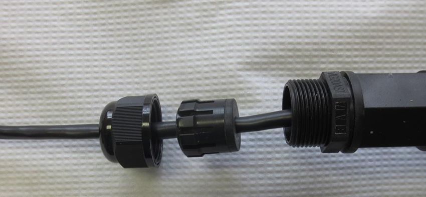
LBDG-100-DC

IMPORTANT SAFETY AND INSTALLATION WARNINGS
WARNING: DO NOT ATTEMPT TO SERVICE THIS PRODUCT
YOURSELF AS OPENING OR REMOVING COVERS MAY EXPOSE
YOU TO DANGEROUS VOLTAGES OR OTHER HAZARDS. REFER
ALL SERVICING TO QUALIFIED SERVICE PERSONNEL.

MOUNTING:
Mount this product only as described in the installation instructions,
otherwise it may fall causing serious personal injury and/or damage to
the device. Use only the brackets supplied with the product. Do not use
attachments not recommended for this product as they may cause
hazards.

SERVICING:
Remove power from this device and refer servicing to qualified
personnel under the following conditions:
   1. If the inside of the station has been exposed to rain or water.
   2. If the station does not operate normally by following the
      operating instructions. Adjust only those controls that are
      covered by the operating instructions as an improper adjustment
      may result in damage and will often require extensive work by a
      qualified technician to restore the unit to its normal operation.
   3. If the unit has been dropped or the chassis has been damaged.
   4. If the unit exhibits a distinct change in performance.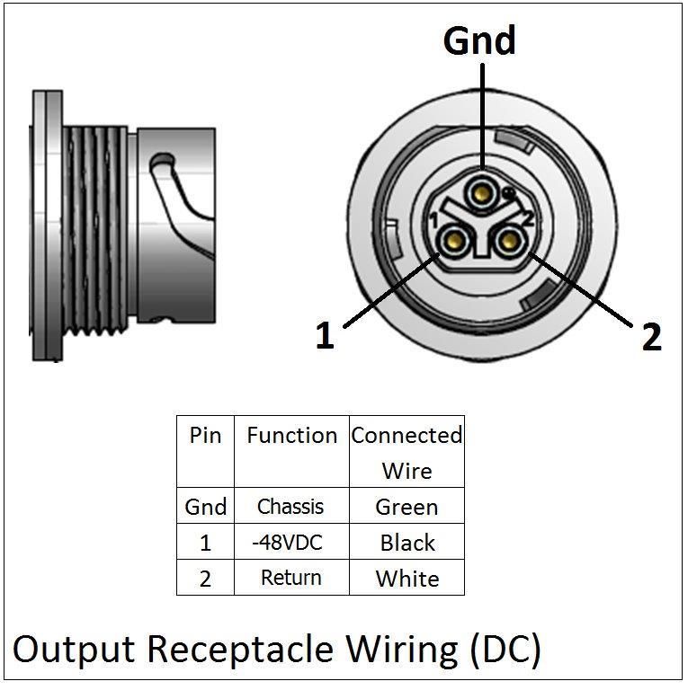
LBDG-100-DC

REPLACEMENT PARTS:
When replacement parts are required, be sure the service technician
has used replacement parts specified by the manufacturer or parts that
have the same characteristics as the original part. Unauthorized
substitutions may result in fire, electric shock or other hazards.

SERVICE DEPOT:
Canada:  Lindsay Broadband Inc.,
         2035 Fisher Dr., R.R. #5
         Peterborough, Ontario K9J 6X6
         (705) 742-1350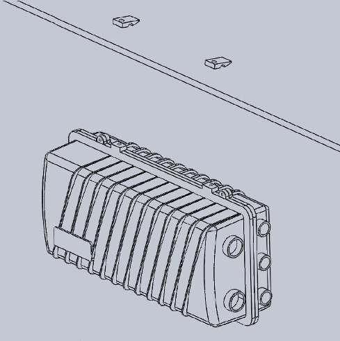
LBDG-100-DC

1.1 Introduction
This manual is written to help service perso nnel understand and install
the Lindsay LBDG-100-DC DOCSIS 3.0 Gateway with DC Power
Output. This first section gives a block diagram and a full product
description. The remaining sections provide component identification
diagrams, installation instructions, and specifications.

1.2 General Description

The DOCSIS 3.0 Gateway uses the HFC network to power and
backhaul IP based devices. It can be connected to the HFC network
through a power-passing coupler or splitter. One heavy guage cable is
used to deliver power to an external device. A total load of 100W is
supported. The cable modem is configured in the standard fashion
using your DOCSIS provisioning software.
LBDG-100-DC
1.3 Housing
A rugged die cast aluminum housing with a clamshell design is used.
Externally, the housing has installation mounts and four connectors:
• A 5/8-24 threaded bushing for KS type connection to the HFC
network.
• A type F test point connector. Signal levels read at this connector
are -20dB relative to the cable modem F port.
• A weather-tight Ethernet port (RJ45 jack) for connection to a
device.
• A weather-tight bayonet style connector for power delivery.
Dual gaskets provide for -100dB EMI isolation and an airtight seal to 15
PSI.
The housing can be strand mounted. An optional hardware kit for wall,
mast or pedestal mounting is available.
The station size is approximately 406 x 228 x 165mm (16 x 9 x 6.5”),
not including connectors. Its weight is around 6.9 Kg (15.3 Lbs).
1.4 Major Components
Internally, the housing bottom contains the HFC interface board and
DOCSIS 3.0 cable modem.
The +12V DC /-55V DC power supply is housed in the lid. This is a high
efficiency switch mode power supply. Filtering to prevent switching
regulator noise from reaching the AC and DC lines is provided.
The lid interconnects to the housing base with a power cable wiring
harness.
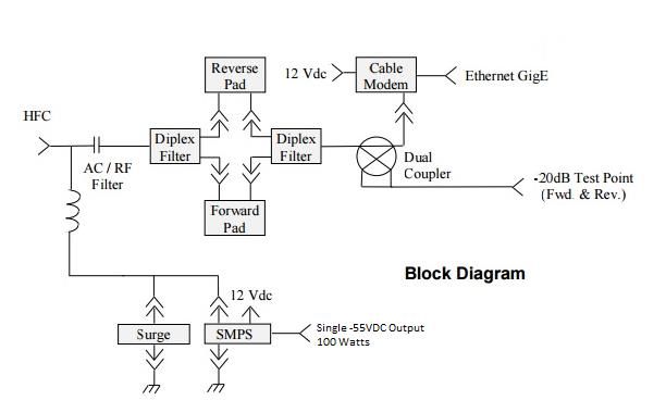
1.5 Interface Board
The interface circuit board, which is located in the housing base,
provides the interface to the HFC network. The following features are
provided:
• An AC/RF filter is used to separate the AC power from the RF
carriers.
• Sockets for the separate padding of forward and reverse DOCSIS
signals.
• A Test Point provides -20dB coupling of forward and reverse
power at the cable modem port.LBDG-100-DC
• Plug-in SVP type surge protection.
• Socket for optional solid state, crowbar type surge protection.
• A power-interrupt to disconnect AC power.
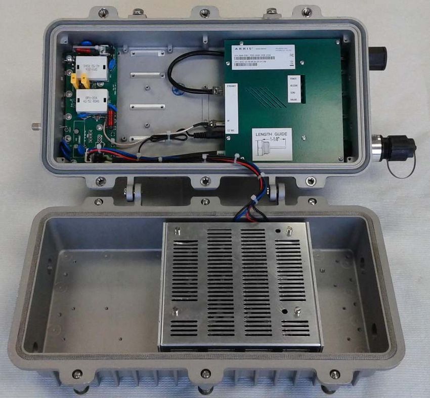
SECTION 2 COMPONENTS IDENTIFICACION
SURGE AC CABLE WEATHER
ARRESTOR INTERRUPT MODEM SEAL
HFC INPUT
ETHERNET GigE
(RJ45)
UPSTREAM &
DOWNSTREAM
PADS
-20dB
F CONNECTOR DC POWER
TEST POINT TO DEVICE
HFC
INTERFACE
BOARD
EMI SEAL
SMPSLBDG-100-DC SECTION 3 INSTALLATION Installation of the LBDG-100-DC DOCSIS 3.0 Gateway is similar to the installation of a line extender or any other piece of CATV equipment. The DOCSIS Gateway can be connected to a power-passing coupler or splitter. Call Lindsay Broadband for the recommended power insertion device for your application. 3.1 Pre-Installation Upon receipt of the LBDG-100-DC, inspect the carton for any external damage. If damage is present, inspect the Gateway exterior for damage. Report any apparent damage to the shipping agent and the Lindsay Broadband sales office. Pad values can be determined ahead of time. The loss of the HFC interface board should be accounted for when calculating pad values. There is -4dB of loss in the reverse direction and -5dB of loss in the forward direction. The forward pad should be selected such that the power incident on the cable modem is 0dBmV ( +5dBmV at the Gateway KS connection). For best return path S/N, the reverse pad should be selected so as to have the cable modem operate near its maximum output level (+50 to +52dBmV). The cable modem can be provisioned ahead of time using the MAC address located on the label on the exterior of the Gateway lid. A ½” wrench is needed for both the strand clamp and housing bolts.
LBDG-100-DC

3.2 Installation Diagrams

        Strand Mount                           Strand Mount
                                           with Hanger Brackets

3.3 Power Requirements

The DOCSIS 3.0 Gateway with DC Power Output can be connected to
any power passing splitter or coupler. The following formula can be
used to calculate the current draw for your installation:

                                       Where:

                                       I      = Current draw in Amps
     I = 1.39 * P                      V      = Line Voltage in Volts
             V                         P      = Total output power
                                                draw in Watts
LBDG-100-DC 3.4 Output Receptacle Wiring
LBDG-100-DC

3.5 Installation

  1. Pull the AC interrupt in the power-passing coupler or splitter.

  2. Using the diagrams in this section as a guide, mount the
     Gateway at its final location. If using hanger brackets, the
     existing strand clamps should be lef t in place to act as spacers
     allowing the same bolts to be used.

  3. Using your KS connector at the Gateway end, m ake a coaxial
     connection to your HFC network at the power-passing coupler or
     splitter.

  4. Replace the 0dB upstream and downstream pads with the pad
     values that were calculated during pre -installation.

  5. Connect the output DC power cable between your device and the
     LBDG-100-DC.

  6. Re-install the AC interrupt. The indicator LED’s on the cable
     modem will indicate start-up, discovery and provisioning. (Refer
     to the cable modem installation guide for more information.)

  7. The forward and reverse RF levels at the cable modem can be
     measured at the single test point. Readings are -20dB below the
     levels seen at the cable modem. Adjust pad values as required.

  8. (Optional) Silicone Grease can be applied to the exposed part of
     the O-ring before swinging the lid back into place. This will
     reduce any tendency of the O-ring to stick to the lid and ensure a
     weather–tight seal. To be clear, use Silicone Grease, not
     Silicone Sealant, nor any other type of grease.

  9. If the EMI gasket has any frayed or loose ends , tuck them back
     into the channel and close the lid while ensuring that the wire
     harness does not interfere with the base and lid sealing surfaces.

  10. Using a torque wrench with a ½” socket, tighten the lid bolts
     gradually, alternating diagonally to avoid stress or warp on the
     housing sealing surfaces. The lid bolts should be tightened to
     the specified 17ftLb or 24Nm torque to ensure that the EMI
     specification is met. The required torque is easily met by using
     the box end of a combination wrench, but cannot be reached
     using a nut driver.

  11. Install your shielded, pre-terminated, outdoor CAT-5e cable as
     shown in Section 3.6.
LBDG-100-DC
12. Tape all connections to reduce moisture intake.
3.6 Attaching the Ethernet Cable
The external RJ45 connector on the Lindsay LBDG-DC Gateway provides an
IP68 weather-tight connection. A cable that is pre-terminated with an RJ45
connector can be used. No tools are required.
1. The parts kit (P/N 3501-288) for the connector contains two glands. The
smaller gland is suitable for cables ranging in di ameter from 4mm to
6.6mm ( 5 / 32 ” - 1 / 4 ”). The larger gland is suitable for cables ranging from
6mm to 10mm ( 1 / 4 ” - 3 / 8 ”). The smaller gland is recommended for cables
that are 1 / 4 ” in diameter.
2. Thread the connector body from the parts kit into the fixed body already
installed in the Gateway. Keep tightening until the flat washer just starts
to compress and bulge outward. This can be done by hand, or with a
wrench however, a light touch is required.
3. Slide the pre-terminated Ethernet cable through the Connector Nut. Apply
the gland and claw, placing the cable though the split in each piece.
4. Push the terminated cable into the fixed body. There should be a positive
click as the RJ45 connector mates with the jack.
5. Push the gland and claw into the connector body. Th en, while pushing the
cable toward the housing, tighten the connector nut. The nut is tight when
the gland can be observed to compress around the cable and bulge
slightly.
Connector Split Connector Flat
Nut Gland Body Washer
and Claw
Fixed
BodyLBDG-100-DC
SECTION 4 LBDG-100-DC HOUSING DIMENSIONS
4.1 Housing Dimensions
TOP VIEW
16.375”
9.750”
RIGHT END SIDE VIEW
6.375”
SIDE VIEW FROM HINGE
1.875”
1.250”LBDG-100-DC
4.2 Table of Specifications
Lindsay LBDG-100-DC Gateway with DC Power Supply Specifications
Cable Modem
Band Plans DOCSIS (Annex B)
Network Configuration and Management TFTP, SNMP (V1, V2c, V3), Telnet, HTTP
Input Impedance 75 Ω
Privacy BPI+
Downstream Modulation 64 or 256 QAM
Modem F
Port +15 to -15dBmV (-10dBmV for 256 QAM)
RF Input Sensitivity (1)
Housing
+20 to -10dBmV (-5dBmV for 256 QAM)
5/8" Port
Upstream Modulation QPSK and 8, 16, 32, 64 or 128 QAM
131.072 Mbps (4 Channels)/32.768 Mbps
Maximum Upstream Data Rate
(Single Channel): @ 128 QAM at 6.4MHz
Modem F
Max. Transmit Power Port +54dBmV (+45 to +51dBmV Recommended)
(ATDMA QAM 64) (1) Housing
+49dBmV (+40 to +46dBmV Recommended)
5/8" Port
HFC
Return Loss -16dB (Max.)
Insertion Loss -5dB (± 1dB)
Test Point -20dB Relative to Cable Modem RF Port
Pad Type JPX, Separate Forward and Reverse
Temperature Range -40 to +60⁰C (-40⁰F to +140⁰F)
EMI Isolation 100dB (5 to 1000MHz)
ANSI-IEEE C62.41 Category B3 (6KV)
Surge Withstand (HFC)
(Gas Tube or Solid-State Crowbar)
Input Powering 40 to 90VAC (Pseudo Sine)
Max. Power Consumption (100W Load) 3.1 Amps @ 60VAC 2.2 Amps @ 90VAC
Output Power
Output Power 100W (Fully Isolated)
Output Voltage -55.8VDC (± 2%)
Efficiency 90%
Power Factor 0.80
Ethernet
Throughput 10/100/1000Mbps
Reach 100 meters
Interface RJ45
Physical
Dimensions 406 x 228 x 165mm (16 x 9 x 6.5")
Weight 6.9 Kg (15.3 Lbs)
Ingress Protection IP68 (15 PSI for 10 Seconds)
Notes:
(1) Levels reported by modem management interfaces reference the modem F port.
Levels at the Gateway KS port incorporate the internal -5dB loss of the HFC Interface.LBDG-100-DC
You can also read