DIY SINGLE CAR GARAGE DOOR - INSTALLATION INSTRUCTIONS
←
→
Page content transcription
If your browser does not render page correctly, please read the page content below
®

DIY SINGLE CAR
GARAGE DOOR

INSTALLATION
INSTRUCTIONS
CONTENTS

1.0   BEFORE YOU START
1.1   Requirements for installation
1.2   Fixing requirements
1.3   Tools Checklist

2.0   BEFORE YOU START
2.1   Install first bracket
2.2   Install second bracket
2.3   Door installation
2.4   Position door
2.5   Tension the springs
2.6   Guide fitting
2.7   Final adjustment
2.8   To adjust spring tension
2.9   Lock holes

3.0   AFTER INSTALLATION
1.0		 BEFORE YOU START
        1.1                           REQUIREMENTS FOR INSTALLATION
        Structural Suitability – Before commencing installation of your new Bastion Single
        Garage Roller Door you must ensure the structure is strong enough to support the
        door. If you are unsure, consult a suitably qualified builder or structural engineer.

        OPENING REQUIREMENTS
        Your Garage Roller Door is designed to be mounted behind the opening therefore
        you will need to measure and check the following;
        OPENING WIDTH – 2500mm
        OPENING HEIGHT – 2200mm
        CEILING HEIGHT – 2650mm minimum
        LEVEL AND PLUMB – This door MUST be installed in an absolutely level position,
        if opening is not level and square, appearance and/or side room will be affected.
n Instructions
        HEADROOM – See diagram below                                                   5
        SIDEROOM – A minimum of 180mm of side room is required beside the opening
S BEFORE INSTALLATION
        to allow for a door opener to be fitted now or in the future.

                                         HEAD ROO M 450mm

                                                                 450mm
         CEILING HEIGHT MIN 2650 mm

                                                               2500mm
                                                               W IDTH

                                                     HEIG HT
                                                                         180mm SIDE RO OM

                                                     2200mm
1.2 FIXING REQUIREMENTS Your Garage Roller Door can be installed on various building materials including Solid or Hollow Brick Work, Timber Framing, Concrete inc. HEBEL and Steel Framing. Important Note: The Installer must select and use fasteners appropriate to the material into which they are being fixed and that these fixings are installed in accordance with the fixing manufactures recommendations. 1.3 TOOLS CHECKLIST Tools required to install your door. You will also need assistance to help lift the door up safety. • a power drill and bits • water level (10mm diameter clear tube by 6m long) • socket set • felt tip marking pen • spirit level • pipe wrench • 2x stepladders • 400mm softwood chock • File • Screwdriver
2.0 INSTALLATION
               NOTE: DO NOT CUT THE PLASTIC WRAP OR PROTECTIVE
               PACKAGING YET

               2.1 INSTALL FIRST BRACKET
               The first step in the installation process is to determine the mounting bracket
               location.
               a)	Measure the door curtain width and mark where the edge of the curtain will be,
                   allowing for an overlap on each side of the opening.
               b)	Mark two hole positions where you intend to secure fasteners through the
                   mounting bracket with a felt tip pen.
or Series 1c)
             Installation     that the intended fixings are located in the centre of the slots on 7
                           Instructions
  ®

              It is important
                        the bracket. This allows for minor levelling adjustments.
NSTALLATION
    d)	Drill both holes, then attach the bracket using your selected fasteners to suit
                        the wall type.
STALL FIRST BRACKET

 an opener is being fitted.

 droom
              2380 mm

Headroom

                                                                                                           180mm
                                                 2380mm

 necessary.
                                                                    10 - 75mm

                                                                                    Line for Edge of Door Curtain
                                                                                    (Check this measurement if an
                                                                                    opener is to be fitted)

                                                   Floor

STALL SECOND BRACKET
er level mark the position for the second
TE: The brackets must be perfectly level      WATER LEVEL
to operate.
180mm
2380mm
2.2 INSTALL SECOND BRACKET
10 - 75mm
a) Using a water level mark the Line
position for
for Edge of the
Door second bracket.
Curtain
(Check this measurement if an
b) It is extremely important thatopener
the isbrackets
to be fitted) are level. This can only be achieved
with
Floor a water level (not a spirit level)
NOTE: The brackets must be installed perfectly level for the door to operate.
ND BRACKET
Re-check levels then drill and fix as with the first bracket.
he second
fectly level WATER LEVEL
rst bracket.
EQUAL EQUAL
HOSE
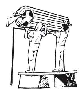
2.3 DOOR INSTALLATION
a) Before lifting the door onto its brackets ensure the axle is sitting in it’s neutral
position by pushing it into the door from one whilst rotating ½ a turn. The axle
will spring
Roll-A-Door Seriesback
® and find
1 Installation it’s neutral position. Mark the position of the
Instructions 8 drum
wheel on the axle with a marking pen for later reference.
2.3 PLACE
b) Lift DOOR
the door onto ON BRACKETS
the brackets (ensure the door is right way so that the door
will roll down from the front of the opening)
a) Check the axle length and cut if sideroom is limited. Before cutting, make sure the floating axle is free and centred. Centre will
be found by rotating the axle a quarter turn in either direction then releasing . With centre found, make a clear mark on the axle
against the hub for later reference.
c) Immediately loosely fit the “U” bolts, saddles washers and nuts to the bracket.
b) Lift door onto the brackets (the right way round so that the door will roll down from the front of the opening). Immediately loosely fit
the “U” bolts, saddles, washers and nuts to the brackets in position shown. Fitting the ‘U’ bolts eliminates the door falling from the
d) Do not over tighten the nuts at this time. Repeat at the opposite end.
brackets. (Do not tighten until Step 2.4, c.)
(a)
(b)
Centering Axle
Axle “Floats” in
either direction2.4 POSITION DOOR
(b)
a) Centre the door with the opening and align the drum wheel with the mark you
left on the axle for this purpose.
b) Check the axles are parallel with the opening.
c) Rotate the curtain axle 1 ½ turns.
d) Securely tighten the “U” bolts.
Considerable tension will be applied to these “U” bolts when the springs are
tensioned so it is important to ensure the “U” bolts are well tightened but not
overtightened so as to distort the saddles.
Cutting or removing the wrapping prior to tensioning the door springs will result
in the door unravelling which may damage the door or result in injury.
the
BOTTOM RAIL AT 3 O’CLOCK
then lift
red with
of the
ning) and
0 Newton2.5 TENSION THE SPRINGS
FIRST PREPARE A SOFT WOOD CHOCK, APPROX. 400MM LONG
a) Tension the springs by spinning the door in the direction as shown in Figure a.
Rotate the door 1 ½ turns in the forward direction to apply tension. Do NOT let
go as the springs are now tensioned.
b) Hold the door firmly, NOW cut the plastic warp along the bottom rail. (taking
care not to damage door surface or weather seal)
c) Once the plastic is released, pull the curtain down slowly and carefully position
ions 9
a softwood chock as shown to prevent the door rolling up. Take care not to
damage the door surface. Figure b.
GS The chock will help hold the door until the guides are fitted.
m LONG.
OCK 1
2
as shown in (a)
apply
ed. See
the bottom
erseal).
(b)
wooden
ake care
s are fitted.
STOP
BOTTOM RAIL LIP
ROLL-A-GUIDE
BOTTOM RAIL2.6 GUIDE FITTING
Guides are supplied in pairs and the correct track for each side must be
identified.
a) Measure between the top of the bracket and the floor on each side of the
opening. In the event you need to trim the bottom of your guides do so now.
The bottom of guide track is the opposite end to the stop welded to the track.
b) Using a rag dampened in kerosene clean the inside of the tracks.
c) Prepare the three mounting clips to each side.
d) Slide the tracks over the exposed door curtain
and fix the tracks to the wall with suitable fixings
allowing a 2-3mm clearance between the inside
guide and the roller door curtain.
e) Position the bottom clip approximately 200mm
from the floor with the rest evenly spaced.
10
f) Ensure the tracks are perpendicular, Figure a. All fixings should be central in the
slot of the track lug to allow for minor adjustments. (Note: if securing to even
brickwork, packers may be required behind the clips)
g) Install and secure all guide mounting clips and fix to wall. Do not tighten fixings
at this stage rather the fixings should be snug fit only.
h) Remove the chock and allow the door to travel to the floor and check for
NYLOFELT
correct tension adjusting guide positions as needed. Tighten all guide fixings
GUIDEsecurely.
r Series 1 Installation Instructions
® LEAD IN
10
i) Ensure the bottom rail is below the door stop weld to the guide and the leads
are bent out sufficiently to allow the curtain to feed into the guide without
IDES snagging. Figure b.
urtain overlaps equally on both sides.
uides are the correct length, that
he brackets (or in the restricted
NYLOFELT
sition are 35mm maximum above
TE: Restricted headroom is not
d when fitting an opener. GUIDE LEAD IN
number of guide clips into each
SPACE
EVENLY
bottom clip 200mm from the floor
evenly spaced along the guide.
ent clips from sliding down the
200mm
rarily secure them with adhesive
osition one guide over the edge of(a)
ain.
(b)
l the top fixed guide clip and secure
m x 8mm coach screw and washer,
m clearance between the inside of
d plastic Roll-A-Guide.
SPACE
de is plumb, drill and fix remaining
EVENLY
f securing to uneven brickwork,
be required behind clips, to prevent2.7 FINAL ADJUSTMENT
1 If your door is hard to operate in ANY DIRECTION check that
the door is not jamming in the guides
Check the following:
a) the guide clearance,
b) that the guides are plumb,
c) that the guide surfaces are clean and free from oil,
d) that the weather seal is impeding movement.
2 If the door is hard to operate in ONE DIRECTION, the spring
tension requires adjustment (see Step 2.8)
a) If the door is hard to lift, but tends to drop, then increase
the spring tension.
b) If the door is hard to close, but tends to rise, then decrease
the spring tension.
3 If the door rolls up crooked as shown below then; check:
a) Brackets are level, refer to Step 2.
tions 12
b) Axle is centralised.
c) Guides are plumb.
that the
m oil;
pring
en
then
e example illustrated - the axle needs moving to the right (to move left they
n cause injury.
pproximately 300mm from each end, as a safety precaution. With the door
he door and with a firm hold on the axle, with a pipe wrench, loosen the
n of the arrow in diagram ). Move the door distance “X” in diagram.en
hen 2.8 TO ADJUST SPRING TENSION (FOLLOW CAREFULLY)
CAUTION MUST BE EXERCISED WHEN UNDERTAKING THIS
STEP SO THAT THE TENSION ON THE SPRING DOES NOT
SLIP DURING THE PROCESS.
e example illustrated
1 With - the
theaxle needs
door moving
rolled up totiethe right
two (to move
ropes left they
around the door roll
cause injury. approximately 300mm from each end, as a safety precaution.
proximately 300mm
2 With from each end,
a person at as a safety
each endprecaution. Withhold
of the door, the door
the axle firmly with a
he door and with a firm hold on the axle, with a pipe wrench, loosen the
large pipe wrench (Stillson) at least 450mm
n of the arrow in diagram ). Move the door distance “X” in diagram.
long
h then re-tighten the otherthe
3 Loosen “U”“”U”
bolt. bolt nuts at both ends and KEEP A FIRM GRIP
ON 7.
de, then refer to Step THE WRENCH.
4 Rotate the axle in the required direction (see diagram)
5 Re-tighten the “U” bolts BEFORE releasing the pipe wrench.
TENSION
6 Test (FOLLOW CAREFULLY)
and repeat if further adjustments are necessary.
ution. TO LOOSEN
SPRING TENSION
y
M
.
TO TIGHTEN
SPRING TENSION
“U” BOLT TO BE LOOSENED
WITHOUT COMPLETELY
REMOVING NUT WHILE
HOLDING ONTO THE AXLE
WITH A PIPE WRENCH2.9 LOCK HOLES
In the case of manual doors only (no automatic opener fitted)
a) Close the door so the weather seal engages the floor but is not compressed
and mark the top of the lock rods accurately on both guides.
b) Drill a hole through the guide using a 12mm bit so that the top of the hole is
5mm below the top of the guide mark.
c) Close the door and with minimum effort compress the weather seal and lock
the door.
d) Adjust the lock hole with a round file to obtain a satisfactory fit of the weather
seal to the floor and easy key operation.
e) Clean off all burrs.
3.0 AFTER INSTALLATION CARE
LOCK –
Your lock does not require special maintenance, however if the keyway becomes
stiff, the application of powdered graphite is recommended – do not grease or oil
the lock.
When opening the door, always remember to make sure the key is drawn from the
lock – if this is not done, the lock mechanism could be damaged and the key could
become bent or broken.
Key Blanks are available by contacting Hartman Pacific customer service on the
number below.
NYLON RUNNING FELT –
Do not under any circumstances grease or apply oil to the nylon tracks or guide
rails. This will cause the track to clog and effect the operation of your door.
An occasional wipe with mineral turps or methylated spirits, down the inside of
each guide, this will remove traces of grease or oil.
After the guides have been cleaned, a silicon spray may be used in the guides.
NOTE: WD40 or similar oil based sprays are not silicon and should not be used.
SPRING TENSION –
It is natural for springs to lose tension over time. When spring tension is adjusted
or when your door is first installed it is usual to apply a little more tension than is
required for balanced operation, to allow for the normal “settling” of the springs.
FOR SPARE PARTS OR FOR TECHNICAL INFORMATION PLEASE CALL
HARTMAN PACIFIC ON 1300 362 393.You can also read