UMS-UTelligent Management System User guide - USystems
←
→
Page content transcription
If your browser does not render page correctly, please read the page content below

UMS—UTelligent Management System

             User guide

          Version:      1.5
          Issue date:   05/01/2019
          Publisher:    Callum Cook, USystems Limited
UMS User guide

Contents

    UMS Overview            ........................................................................................................        3

    UMS Power supply
    Specification           ........................................................................................................        4

    UMS Quick starter
    guide                   ........................................................................................................        5

    GUI

       Overview             ........................................................................................................        6

       Dashboard            ........................................................................................................     7-9

       Fan speed            ........................................................................................................       10

       Environmental        ........................................................................................................       11

       Security             ........................................................................................................       12

       Alerts               ........................................................................................................   13- 14

       Reporting            ........................................................................................................   15 - 18

    Settings

       Network Settings     ........................................................................................................       19

       SMTP                                                                                                                                19

       Device Manager       ........................................................................................................   19 - 20

       User Accounts        ........................................................................................................       20

       Sensor Names         ........................................................................................................       21

       SNMP                 ........................................................................................................       21

                   Page number 2 +44(0) 1234 761720 sales@usystems.co.uk www.usystems.co.uk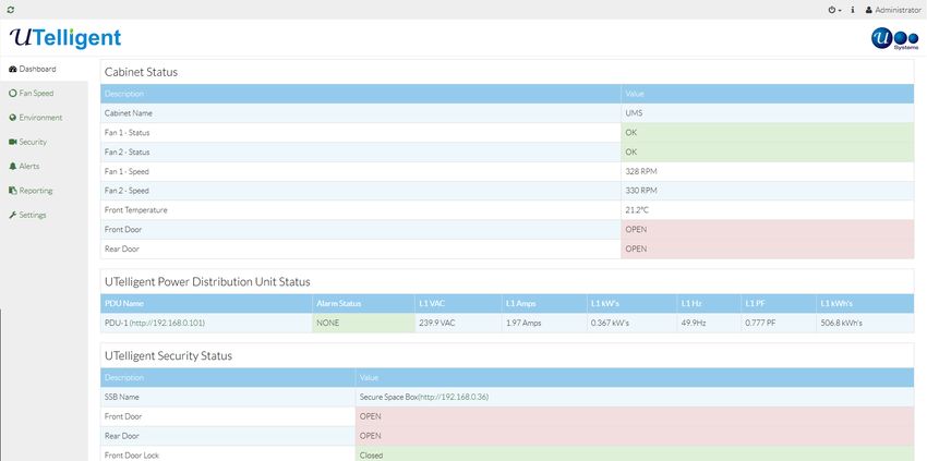
UMS User guide

 Product Description

 The UTelligent Management System ‘UMS’ is a networkable, environmental, monitoring and security product allowing
 you to monitor and control your IT cabinet to its fullest potential.

 This following is a list of devices currently available to install into and on to your cabinet via the UMS

    - Temperature sensors

    - EC Fans up

    - IP Camera system, front, rear or both options

    - Contact sensors

    - Aisle containment door open/close

    - UTelligent Power Distribution Unit

    - UTelligent Locking

    - Direct monitor/touch screen (coming soon)

 Document overview

 This user guide describes how to use the ‘UMS’, Web User Interface ‘WebUI’ and relevant hardware provided with the
 device.

                     Page number 3 +44(0) 1234 761720 sales@usystems.co.uk www.usystems.co.uk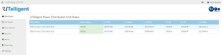
UMS User guide

  UMS Power Supply Specification

  2.1A IEC Power supply

Output Voltage                   5 VDC
Maximum output current           3.00 ~ 2.50 A
Power (watts)                    15 W
Full input voltage range         90 ~ 264Vac
Full frequency range             47 ~ 63Hz
Input current (RMS Max.)         0.5A @ 230VAC, 0.5A @ 115VAC
Safety Approvals                 EN60950 (TUV), UL60950, CE
Line Regulation                  +/-0.5-1% typically @ full load
Load Regulation                  +/-3-5% typical @ 230 VAC input
Hold Up Time                     8 ms min @ 110 VAC typ
Leakage Current                  0.75 mA max
Isolation Voltage                I/P-O/P: 3 kVAC
Operating Temperature            0°C to +70°C (100% load to 40°C, derates to 50% @ 70°C)
Dimensions                       104(L) x 42(W) x 31(H) mm

                       Page number 4 +44(0) 1234 761720 sales@usystems.co.uk www.usystems.co.uk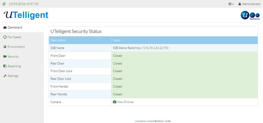
UMS User guide

 UTelligent Management System ‘UMS’ Quick starter guide
 1.   The UMS is delivered from USystems with default settings, please refer the UMS manual for these settings.
      These settings should be adequate for most installations, however you might with to adjust them to suit your
      own requirements.

 2.   The UMS and each fan will need to be plugged into the mains supply.

 3.   It is recommended to power on the UMS first before applying power to the fan. Failure to do so will result in the
      fans running at full speed until the UMS has completed its boot up and started to control them.

 4.   The LED in the door will light up either red or green which indicates the UMS is powered on and working. If LED
      does not light up, please check that both LED cables are plugged into the UMS with no loose connections.

 5.   In order to use the WebUI (Web User Interface), an Ethernet cable to your network is needed. Plug the Ethernet
      cable into the UMS RJ45 port and then to a live network port onto your own network. The network port on the
      UMS will light up to show it is live.

 6.   The default IP address to log on to the UMS is 192.168.0.100, please contact your network administrator if you
      are unable to load the log in screen.

 7.   The default login is ‘admin’ and the password is ‘Admin12$’

 8.   You must accept the EULA to proceed onto the WebUI

 9.   The following pages detail modifying default settings - Page 18 -19

                  Page number 5 +44(0) 1234 761720 sales@usystems.co.uk www.usystems.co.uk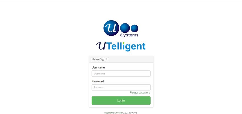
UMS User guide

  WebUI ‘Web User Interface’ Overview

  The UMS is an environmental, monitoring, security and networkable product, delivered with a default IP Address
  of 192.168.0.100 and a Net mask of 255.255.252.0

  The WebUI can be accessed using the default IP address in the address bar of any browser from any type of
  device there is a default Administrative account which to login to requires the following credentials:

  Default username: ‘Admin’

  Default password: ‘Admin12$’ (case sensitive)
  If unable to connect please contact you Network administrator to allow the use of this IP address or connect directly to the
  UMS via ethernet and adjust your IPv4 properties to match.

  Once you have accepted the EULA you will be redirect to the dashboard page once logging in successfully. By not
  accepting our EULA you will not be allowed entry to the UMS software.

                     Page number 6 +44(0) 1234 761720 sales@usystems.co.uk www.usystems.co.uk
UMS User guide
WebUI - Dashboard 1
The dashboard is made up of different tables depending on your cabinet configuration.
Header
The header includes the time and date it is set to UK London time zone - please see page 18 settings to change this.
Power icon that has a drop down menu to Restart, Upgrade, Remote support and Log out.
Restart - Selecting this with restart the UMS
Upgrade - This option is available to upgrade the UMS. To use this you will need a USB fob from USystems that has the new
software on it. Insert the USB fob into the USB port on the UMS and select the Upgrade icon. It will go through the sequence
which can take up to 3 minutes.
SupportMe! - This is to enable the VPN connection with USystems so that a remote support connection can be established.
Once the UMS is restarted the VPN connection will be disabled and you will need to select it again to enable it.
Log out– Selecting this will log you out of the UMS and return you to the log in screen.
i icon directs you to this manual installed on the UMS.
Show the current user that is logged in to the UMS
Menu
Left side of the dashboard is the menu with a list of different options these areas can be locked out for certain users - please see page
19 for user accounts.
Cabinet Status Table
Cabinet name: By default it is names as UMS - please see page 18 settings to change this. It is also the hostname for the device.
Fan Status: Displays the fan status and its value being either ‘OK’ or ‘FAIL’ - please see page 10 for fan alarm information
Fan Speed: Displays the RPM (Revolution per minute) of each fan
1-Wire: The current temperature will be displayed along with the sensor location, it can be displayed in °C or °F
Each sensor can be provided with a customer name, this can be done under Settings - Sensor names.
Digital sensors: Contact sensors will display if the cabinet is open or closed.
Page number 7 +44(0) 1234 761720 sales@usystems.co.uk www.usystems.co.ukUMS User guide
WebUI - Dashboard 2
The dashboard is made up of different tables depending on your cabinet configuration.
UTelligent Security Status Table
This will show the SSB product which also has a link to the UTelligent Secure Space Box web management software. You will be
able to view status of each contact sensor, door lock and handle. When used/opened the value will change to ‘OPEN’.
To add the UTelligent secure space see page 16
If you have opted to have a camera in the cabinet you can view the pictures by clicking on the ‘view entries’. please see page 12 for camera.
Page number 8 +44(0) 1234 761720 sales@usystems.co.uk www.usystems.co.ukUMS User guide
WebUI - Dashboard 3
The dashboard is made up of different tables depending on your cabinet configuration.
UTelligent Power Distribution Unit Status Table
Reads and displays UTelligent PDU(s) status. This is not set up by default and will require activation, please see page 16 for
details.
Under the PDU Name category will be your assigned PDU and a link to the PDU’s WebUI, this will only display value’s from the
PDU all changes needing to be made on the PDU will need to be carried out via the PDU web management software.
The link will not give you automatic access to the PDU’s WebUI, you will still need to provide your login information.
Page number 9 +44(0) 1234 761720 sales@usystems.co.uk www.usystems.co.ukUMS User guide
WebUI - Fan Speed
The Fan speed page will allow you to set an alarm if there is a Fan Fail.
To enable an alarm, select Fan Speed from the left hand column. Select the ‘on’ button and enter at least one email address of
those that need to receive a notification. See page 16 to set up SMTP settings (emails).
Fan Speed Curve should not be changed by anyone who does not understand ‘Ramp rates’ which should be set dependant
upon the equipment being used inside of the cabinet.
Ramp rate: Is the rate at which the fans speed up per degree Celsius from the Base speed. They will keep speeding up
at this rate until they are running at 100% (10V) i.e. they are not capped. They will hit 100% at a temperature depend-
ant on the ramp rate set. This does not require a restart it will change once you apply and save the settings.
There will be 2 different set ramp rates which are listed in the table below and a custom option which allows you to change
the ramp rate by increasing/decreasing the percentage of fan speed per degree.
Aggressive Standard
Ramp Rates
100%
90%
80%
70%
60%
Fan speed %
50%
40%
30%
20%
10%
0%
0°
0°C 24°
24°C 28°
28°C 32°
32°C 36°
36°C 40°
40°C 44°
44°C 48°
48°C 52°
52°C
32°F 75°F 82°F 90°F 97°F °C
Temperature 104°F 111°F 118°F 125°F
Page number 10 +44(0) 1234 761720 sales@usystems.co.uk www.usystems.co.ukUMS User guide
WebUI - Environment
The environment page allows setting of alarms on over temperature. The Alarm will be set off if the temperature reaches the
set threshold in degrees °C/°F which can be changed either using the arrows provided or by manually entering it by selecting
the text field in between the arrows.
Click on Environment in the left hand column, select the ‘on’ button. Set the alarm temperature you wish to be notified of
when temperature reaches the select number. Enter in at least one email addresses into the email section at the bottom for
those that need to receive the emails. See page 16 to set up SMTP settings (emails).
Click Save settings to set all changes
Page number 11 +44(0) 1234 761720 sales@usystems.co.uk www.usystems.co.ukUMS User guide
WebUI - Security
The Security tab is only activated if you have purchased either a camera front and or rear, or contact sensors.
Photographic Security Records
To view the photos taken select the View picture or Download picture. The default view will show 10 images per page and it
can be change by selecting the drop down menu to view more per page.
To receive email access alerts to inform someone/people that a contact sensor has been triggered the ’Tigger Alert’ has to be
changed to ‘ON’ and at least one email recipient has to be set. See page 16 to set up SMTP settings (emails).
Once desired options are chosen click Save settings.
Page number 12 +44(0) 1234 761720 sales@usystems.co.uk www.usystems.co.ukUMS User guide
WebUI - Alerts 1
The UMS has an alert option which will alert on the date you select. When the Alert is triggered the LED on your enclosure with
change to Amber.
Service Alert
USystems are able to provide your enclosure with a service when ever you need. For more information on what is offered in a
service please contact USystems.
To activate this option simple select the ‘On’ button and click on the date to choice or type it in yourself, then select save.
Page number 13 +44(0) 1234 761720 sales@usystems.co.uk www.usystems.co.ukUMS User guide
WebUI - Alerts 2
The UMS has an alert option which will alert on the date you select. When the Alert is triggered the LED on your enclosure with
change to Amber.
Filter Alert
Depending on the environment that the enclosure is situated could result in the enclosure absorbing dust so we recommended
to each customer to use a filter to prevent your IT equipment from unwanted material in the air. If your enclosure has a filter
we also recommend using this feature to notify you of when you should replace it.
To activate this option simple select the ‘On’ button and click on the date to choice or type it in yourself, then select save.
Page number 14 +44(0) 1234 761720 sales@usystems.co.uk www.usystems.co.ukUMS User guide
WebUI - Alarms Reporting
Alarms Log
The Alarms Log report is a list of alarms recorded up to 3 months. This includes Fan fail, access and temperature over threshold
data, reports of the data are available to download onto an .csv spreadsheet.
The records may be displayed 10, 25, 50 or 100 per page.
Search by date and time using the same format.
Page number 15 +44(0) 1234 761720 sales@usystems.co.uk www.usystems.co.ukUMS User guide
WebUI - Temperature Reporting
The Temperature Log report is a list of temperature recorded up to 3 months. Reports of the data are available to download
onto an .csv spreadsheet.
The records may be displayed 10, 25, 50 or 100 per page.
Search by date and time using the same format.
Page number 16 +44(0) 1234 761720 sales@usystems.co.uk www.usystems.co.ukUMS User guide
WebUI - Fan Reporting
The Fans Log report is the list of fans connected to the UMS and it’s RPM output recorded up to 3 months. Reports of the data
are available to download onto an .csv spreadsheet.
The records may be displayed 10, 25, 50 or 100 per page.
Search by date and time using the same format.
Page number 17 +44(0) 1234 761720 sales@usystems.co.uk www.usystems.co.ukUMS User guide
WebUI - Access Reporting
The Access Log report is the list of actavations made from a contact or multiple contact sensors being released by a door or
side panel being opened. These are recorded up to 3 months. Reports of the data are available to download onto an .csv
spreadsheet.
The records may be displayed 10, 25, 50 or 100 per page.
Search by date and time using the same format.
Page number 18 +44(0) 1234 761720 sales@usystems.co.uk www.usystems.co.ukUMS User guide
WebUI - Setting
Network Settings TAB
This gives you the ability to change the network details of the device and also the device name which can help identify each
device where there are multiple UMS based accessories/cabinets.
The default network settings are as follows:
Device name: Cabinet
DHCP: Set to ‘Off’
IP address: 192.168.0.100
Netmask: 255.255.252.0
Gateway: 0.0.0.0
To change these settings select the text fields and adjust accordingly and then click save settings. If the IP address is to be
changed you will need to reconnect using the new IP address. Do this by selecting restart from the power icon button on the
top right of the screen, allows 2-3 minutes for it to power on fully with the new IP address.
NTP Server IP: To change to a different NTP Server enter it’s IP Address and use the save button, a restart of the UMS is
required to apply these settings.
MAC address: Displays device's MAC (Media Access Control) address. This cannot be changed.
To change the date and time for your country select the drop down menu and select your time zone and restart the UMS for
the setting to change.
SMTP Settings
This must be set to allow emails alerts/alarms to be sent. The server you are wanting to use must be SSL/TLS enabled. The
default settings do not need to be changed as this will work by default.
Server address (IP/Domain): Add the IP or Domain of your email server
Username: Add the email address that you wish to send the alerts/alarms from
Password: Add the password of the email address you are wanting to use
Make sure that the default admin email address is changed to the administrator who is going to be receiving emails to change
passwords of users that request a forgotten password.
To allow Gmail to work on this device, you will need to enable less secure apps. To do this log into your Gmail account -
https://myaccount.google.com/lesssecureapps
To make sure that the setting used are correct select the ‘Save Settings’ button. Under the Environment menu insert an email
address that you wish to use to receive a test email. You do not need to turn the temperature alarm on to receive a test email.
Save Settings and go back to ‘Settings’ - ‘SMTP’ menu then select ‘Send Test Email’ button. If configured correctly you should
receive an email.
Device manager
This tab details all devices that are attached to the UMS. When adding new devices to the UMS cross check in device manager
that they are displaying correctly.
Hardware Version - This displays the hardware version of the UMS. This may be required for support.
Software Version - This displays the software version of the UMS. This may be required for support.
Fans Count - This displays the amount of fans that are allowed on this device.
Temperature Sensors Detected - This is the amount of temperature sensors the UMS is detecting.
Digital Sensor Count - This is the amount of digital input output detected on the UMS.
Page number 19 +44(0) 1234 761720 sales@usystems.co.uk www.usystems.co.ukUMS User guide
Device manager
Default Units - This options allows you to change from Metric to Imperial
Temperature Sensor Set - If you have added more than one temperature sensor, select the drop down and select how
many you have imputed into the UMS. This will allow the UMS to detect if it is not being detected and there is a fault.
Digital IO-1 Type - 2Pin connector - Contact sensor or Aisle containment door ‘Open’ or ‘Close’
Digital IO-2 Type - 3Pin connector - Contact sensor or Servo (controlling air ducting flap)
Digital IO-3 Type - 2Pin connector - Contact sensor or Aisle containment door ‘Open’ or ‘Close’
Digital IO-4 Type - 2Pin connector - Contact sensor or Aisle containment door ‘Open’ or ‘Close’
Digital IO-5 Type - 3Pin connector - Contact sensor
Digital IO-6 Type - 2Pin connector - Contact sensor or Aisle containment door ‘Open’ or ‘Close’
Camera - If you have purchased an IP Camera from USystems select enabled.
Camera Front - Add the IP Address shown on the box. This IP Address cannot be changed
Camera Rear - Add the IP Address shown on the box. This IP Address cannot be changed
It enables UTelligent Locking and UTelligent PDU’s to be added via their IP address into the text boxes and selecting the
save icon when complete.
UTelligent Hub Address - This is used when you have a UTelligent Hub on the same network. Add the IP Address of the
Hub so that the UMS will show on the UTelligent Hub
User Accounts
On first login to the device you will have a default login (‘Admin’) and password (‘Admin12$’) we recommend changing
the Admin login password.
To add a new user select the button at the bottom of the table in blue ‘Add user’ you will then fill the fields with the
required information. Make sure you activate the account otherwise the account will not work until activated.
There are 5 levels of access -
R (Read-only user) can only access DASHBOARD TAB
RC (Read-only + camera user) can only access DASHBOARD + Camera TAB
W (Write user) access to all TABs other than Camera and UMS settings TAB
WC (Write and Camera user) can access almost all TABs other than UMS Settings TAB
S (Super-user) can access all TABs
Once completed select ‘Save Settings’.
Passwords must be a minimum of 8 characters with at least 1 number and 1 upper case letter.
If you do not require the account you have two options depending on the situation. If the user is no longer needed for the
foreseeable future you can delete the account by selecting the bin icon in the users row you wish to delete. You also have
the option to deactivate the account in the event that it needs to be suspended, this is achieved by selecting the tick icon
on the users row. To reactivate it, select the cross icon. These options can only be performed by the admin account or
super user.
You may also change the email address of the account by editing the text field under email and select save icon when
finished, this is the same for the Access level. Enter the user rights by the corresponding letters list in on information panel
and selecting save once completed, a confirmation pop up will appear if correct. If incorrect entries have been entered a
different pop up will appear showing you the error inputs.
Page number 20 +44(0) 1234 761720 sales@usystems.co.uk www.usystems.co.ukUMS User guide
Sensor Names
The table displays each sensor assigned to the UMS and provides the ability to name each device. To change the name,
select the text field and retype what you wish to call the device. A good example would be to name a contact sensor in the
front to ‘Front door’ which will show on the dashboard.
SNMP
To receive data from the UMS using SNMP V2 enter the IP address of your SNMP Trap Receiver, select ‘on’ next to SNMP
Active. Save the setting and send a test trap to confirm completion.
Page number 21 +44(0) 1234 761720 sales@usystems.co.uk www.usystems.co.ukYou can also read