XL Motion Controller Datasheet - Waterbird Systems
←
→
Page content transcription
If your browser does not render page correctly, please read the page content below
XL Motion Controller

                              Datasheet
                                          Version 1.3

Copyright © 2021 Waterbird Systems GmbH
www.waterbird.at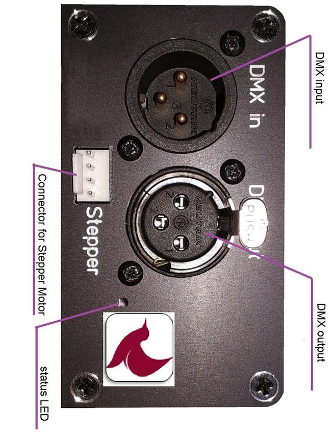
Table of Contents

1.     Introduction ................................................................................................................................. - 1 -
     1.1      Technical Data ..................................................................................................................... - 1 -
     1.2      Interface Definition ............................................................................................................. - 3 -
     1.3      Application Diagram ............................................................................................................ - 6 -
2.     DMX Command List ..................................................................................................................... - 7 -
3.     Control Unit Communication Configuration ..............................Fehler! Textmarke nicht definiert.
4.     Control Unit Communication Configuration ............................................................................... - 9 -
5.     Handling and Safety Instructions .............................................................................................. - 10 -
     5.1      Troubleshooting ................................................................................................................ - 11 -
     5.2      Regulatory Hints ................................................................................................................ - 12 -

Copyright © 2021 Waterbird Systems GmbH
www.waterbird.at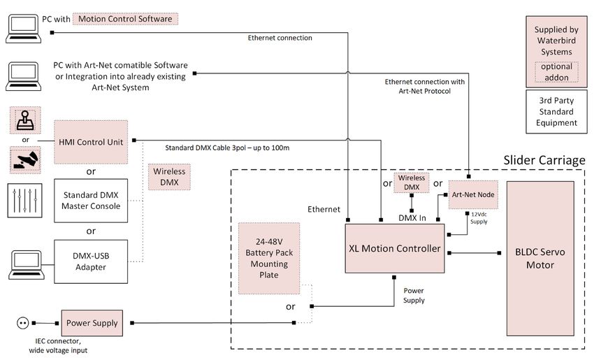
Multi Slider – User Manual

1. Introduction
The XL Motion Controller is a controller for timelapse and digital motion control for video and
photo equipment. It allows to control one of two motor types (Clearpath BLDC motor or
bipolar Stepper motor) and the triggering of shutter and focus of a connected camera. Most
models of popular cameras are supported. Auxiliary input / output port for customer defined
additional equipment is also available besides a 12Vdc stabilized output for powering of
additional equipment like Art-Net Nodes or wireless equipment.
In addition to the Control Unit of the Standard Multislider System the XL Motion Controller
allows the control via DMX protocol as well as connecting to an ethernet based IP system.
For control via Ethernet the PC Software Motion Control Software is offered.

1.1 Technical Data
 Housing
 Measurements                    123 x 78 x 43mm without connectors and mounting
                                 brackets
 Housing Material                aluminum, black anodized

 Operating Parameters

 Temperature Range               -20°C to +40°C (-4°F to 104°F)
 Maximum Relative Humidity       90%, noncondensing

 Ports & Connection

 Supply Connector                Molex 039301020
 Supply Voltage                  12 –48 Vdc stabilized voltage
 Supply Current                  200mA without external load

 12V Out                         Stabilized 12Vdc Output.
                                 max output current 1,5A (if no Stepper Motor used)
                                 max output current 1A (if Stepper Motor used)
                                 output switchable and current monitored by Software
                                 can be used for auxiliary equipment on Slider, e.g. cameras,
                                 Wifi or RF equipment.

 Motor Output 1                  Molex 03930-1080
                                 For connecting to a Teknic Clearpath SDSK Series Motor
 Motor Output 2                  Molex 22-05-3041
                                 For connecting a bipolar 4-wire stepper Motor,
                                 maximum output current 1A
                                 minimal isolation voltage of motor >16V

Copyright © 2021 Waterbird Systems GmbH
www.waterbird.at                                                                           -1-
Multi Slider – User Manual

 Camera Trigger Port           2,5mm (3/32”) Stereo Jack / TRS
                               Sleeve: GND, Ring: Focus, Tip: Shutter
                               Internal pull-up 3,3V, max. external pullup Voltage: 5Vdc

 Auxiliary Port                3,5mm (1/8”) Stereo Jack / TRS
                               Sleeve: GND, Ring: Aux 2 In/Out, Tip: Aux 1 In/Out
                               Internal pull-up 3,3V, max. external pullup Voltage: 5Vdc

 USB Port                      USB Micro B
                               Used for Firmware Updates and Parametrization
                               5Vdc supply for electronics, no supply of motors via USB

 DMX in                        3 -pole male XLR receptacle
                               Input for DMX control signal. Standard DMX512 Signal with
                               250kbaud supported.
 DMX out                       3-pole female XLR receptacle
                               Output for DMX control signal for additional equipment.
                               Loop through of input signal.

 Network                       RJ45 Ethernet Connector
                               for IP based control

Copyright © 2021 Waterbird Systems GmbH
www.waterbird.at                                                                          -2-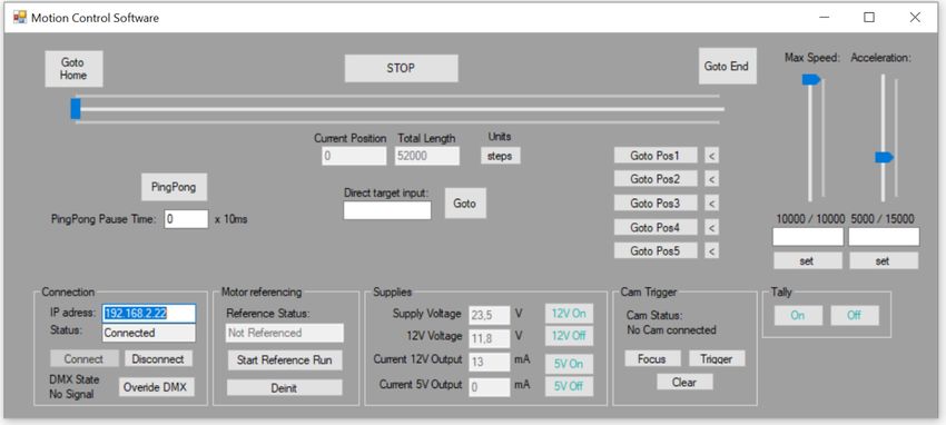
Multi Slider – User Manual

1.2 Interface Definition

Copyright © 2021 Waterbird Systems GmbH
www.waterbird.at                          -3-
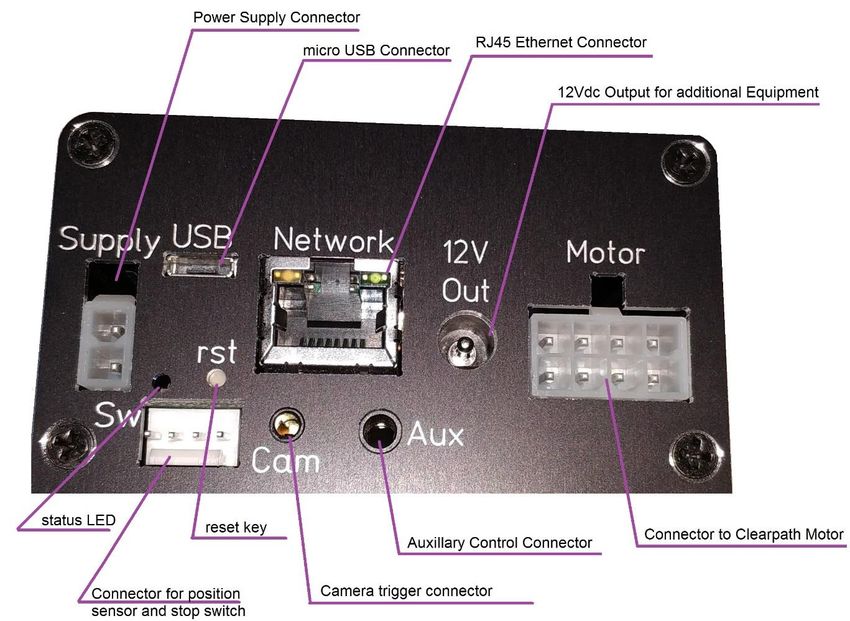
Multi Slider – User Manual

Power Supply Connector
The Power Supply Connector is the power source for the XL Motion Controller and the Stepper
Motor. The Clearpath Motor is not powered from the XL Motion Controller but directly via
power supply.
A stabilized DC voltage between 12-48 Vdc must be used (24-48V for Clearpath Motor).
Typically, this voltage is supplied via an AC/DC power supply or via a Battery pack.

Camera Trigger Connector
Control Unit can control a camera through the wired remote shutter port with 2.5mm Stereo
Jack (3/32” Male TRS) connector. Standard Cables are available for most camera models on
the market.
The Camera Trigger Connector provides control over the focus and shutter trigger only, it is
not possible to control ISO, aperture, or other settings of the camera over this port. If you set
your camera to bulb mode, the control unit can control the shutter speed (if your camera
supports this mode).

LED Indicator
The LED Indicator shows the current status of the Control Unit. If no light is visible the Control
Unit is unpowered.
If the LED Indicator is flashing slowly the Control Unit is waiting for a connection to a Control
device.
If the LED Indicator is constantly on, the Control Unit is connected and ready to be used.
If the LED Indicator is flashing quickly the Control Unit is in an error state.

USB Connector
The USB connector can be used for firmware updates. Powering the Control Unit via USB is
only possible for firmware updates, no motor control is possible if no power is available on
the Power Supply Connector.

Auxiliary Connector
This Port can be used to connect accessories like a manual knob or external controls e.g. to
control a light that is switching on and off before and after the picture is taken for a long
duration time-lapse.

Copyright © 2021 Waterbird Systems GmbH
www.waterbird.at                                                                              -4-
Multi Slider – User Manual

Stop Switch Connector
To this Port the magnetic stop switch is connected to. This allows the automatic detection of
slider length during reference run.

Reset
This button can be pressed to reset the internal processor of the Control Unit. This also causes
a sudden stop of all connected motors.

Copyright © 2021 Waterbird Systems GmbH
www.waterbird.at                                                                            -5-
Multi Slider – User Manual

1.3 Application Diagram
The Control Unit is typically used in the following Setup:

Copyright © 2021 Waterbird Systems GmbH
www.waterbird.at                                             -6-
Multi Slider – User Manual

   2. DMX Command List
The Control Unit uses 16-DMX channels. The start address of the DMX channels is per default
address 1. The start address can be changed via a PC program via Control Unit Config tool, see
chapter “Control Unit Communication Configuration”.
The commands are:
   Channel        Value                                      Function
      1           0..255     Target position of Slider
      2           0..255     Fine setting Target position of Slider
      3           0..255     Speed of Slider Movement
      4           0..255     Fine setting Speed of Slider Movement
      5           0..255     Acceleration of Slider Movement
      6           0..255     Fine setting Acceleration of Slider Movement
      7           0, 100     Mode of Slider Operation:
                             0 : Normal operation - Slider follows DMX target position
                             100: Automatic Ping-Pong Movement - Slider moves from start to end
                             position and back continuously (target setting is ignored, speed and
                             acceleration are used from DMX values)
                             all other values: reserved - do not use

       8          0, 100     Slider referencing:
                             0 : Normal operation
                             100: for more than 1 sec - starts the reference run of slider
                             all other values: reserved - do not use
       9          0..255     12V Output switching:
                             100 : Output is set off
                             150 : Output is set off for 1 sec and then switched on again (e.g. to
                             reset an external Wifi device)
                             200 : Output is set on
                             all other values: ignored - no state change
      10           0..3      Cam trigger out:
                             0 : Cam outputs are off (high state)
                             1 : Cam Focus is on (pulled to ground)
                             2 : Cam Shutter is on (pulled to ground)
                             3 : Cam Focus + Shutter is on (pulled to ground) (info: most camera
                             models need the focus also activated during shutter release)
                             all other values: reserved - do not use
      11            0        reserved for further use - set to 0
      12            0        reserved for further use - set to 0
      13            0        reserved for further use - set to 0
      14            0        reserved for further use - set to 0
      15            0        reserved for further use - set to 0
      16            0        reserved for further use - set to 0

Copyright © 2021 Waterbird Systems GmbH
www.waterbird.at                                                                                     -7-
Multi Slider – User Manual 3. Control via Ethernet The XL Motion Controller allows to control the Slider Movement and auxiliary functions via Ethernet. For this the Motion Control Software is available. For control via Ethernet the XL Motion Controller needs to be attached to an Ethernet network and the IP address has to be set according to your network needs. For setting the IP address see chapter “Control Unit Communication Configuration”. At startup of the Motion Control Software the IP address of the XL Motion Controller needs to be entered and the connection is started by clicking the “Connect” button in the left bottom. After successful connection, the Status in the connection area shows “Connected” and the slider can be referenced. For this click the “Start Reference Run” button – the slider moves to both ends to learn the length and position of the system. After referencing, the Slider can be controlled manually to a certain position by dragging the virtual position slider on top of the user interface to a certain position or entering the desired position in the “Direct target input” box and pressing “goto” button. Via the controls on the right the speed and acceleration of the slider movements can be changed. Current position can be saved by clicking on the small arrow buttons right to the “Goto Pos” buttons. To move again to the stored position, click in the corresponding “Goto Pos” button. The “PingPong” button activates the automatic movement between the two end positions and allows to set a pause time between the movements. Copyright © 2021 Waterbird Systems GmbH www.waterbird.at -8-
Multi Slider – User Manual

4. Control Unit Communication Configuration
The Control Unit Config Tool allows to change the DMX start address and to change the IP
address of the control Unit.

For changing the settings use a Micro-USB cable to connect the control Unit to a PC running
MS Windows 10 and start the Control Unit Config Tool.
The current values will be shown on startup of the tool. In the white fields the values can be
changed according to your application needs and then be written to the XL Motion Controller
by clicking on the corresponding “Write” button.
The DMX Start address will be taken over instantly while the new IP address needs a power
cycle of the XL Motion Controller to become active.

Copyright © 2021 Waterbird Systems GmbH
www.waterbird.at                                                                          -9-
Multi Slider – User Manual

5. Handling and Safety Instructions
The Control Unit is designed to be mounted in the slider’s carriage by 4 screws. Do not use
another method of fixing the Control Unit to the Slider.
Do not use the Control Unit in wet or humid environment like rain, snow, spray or waterfalls
without extra protection against humidity intrusion into the electronics.
Do not install this Unit near a heater, inflammable material or oily or dusty location or in a
location continuously exposed to direct sunlight or in a location where gas may leak.
Do not cover the Control Unit with metal objects to ensure proper operation of the wireless
communication.
Do not attempt to repair, disassemble, or modify the Unit by yourself. There are no serviceable
parts inside and opening the Unit will void the warranty.
Remove all foreign substances such as dust or water from the terminals using a dry cloth on a
regular basis. - Unplug all connectors and clean it with a dry cloth without alcohol or other
solvents.
Do not pull or excessively bend the cables. Do not twist or tie the cables. Do not hook the
cables over a metal object or place a heavy object on the cables. Do not pull the cables, when
unplugging. Pull out the cable only by holding the plug. Do not put force on the cables in any
direction when connected to the Control Unit, this can damage the Control Unit and
connectors.
Before switching on the power to the Control Unit ensure that the Motors can spin freely and
no harm to humans, animals or objects is possible in case the connected motors start moving.
Do not use the Control Unit if it is damaged, the isolation on the cables is damaged or it shows
any abnormality like excessive heat dissipation.
It is normal that the Control Unit gets warm during operation. To avoid overheating do not
cover the Control Unit with thermally insulating material and allow free airflow.

Copyright © 2021 Waterbird Systems GmbH
www.waterbird.at                                                                           - 10 -
Multi Slider – User Manual

5.1 Troubleshooting
Camera does not trigger/focus when function is used.
   •   Please check the trigger cable if properly plugged into the control unit’s CAM socket
       and to the camera.

   •   Check if the Camera is switched on.

   •   If focusing is not working check if the camera/lens is set to manual focus.

   •   Some cameras require settings in the menu to allow external trigger cable to be used,
       please check with the manual of your camera.

Motor does not start when function is used.
   •   Please check if the motor cable is properly plugged into the control unit’s Motor socket
       and motor is supplied by required voltage.

   •   Check if the power supply is connected. If only USB is connected the Control Unit may
       connect to the App or PC program, but the motors will not work.

   •   Check if supply voltage is in range (The battery may be empty.)

   •   Check if any error information is shown in the PC program or App.

Copyright © 2021 Waterbird Systems GmbH
www.waterbird.at                                                                          - 11 -
Multi Slider – User Manual
5.2 Regulatory Hints
INSTRUCTION ABOUT THE WEEE MARK
Correct Disposal of This Product (Waste Electrical & Electronic Equipment)
(Applicable in countries with separate collection systems) This marking on the
product, accessories or literature indicates that the product and its electronic
accessories (cables, adapters,..) should not be disposed of with other household
waste at the end of their working life. To prevent possible harm to the environment or human
health from uncontrolled waste disposal, please separate these items from other types of
waste and recycle them responsibly to promote the sustainable reuse of material resources.
Household users should contact either the retailer where they purchased this product, or their
local government office, for details of where and how they can take these items for
environmentally safe recycling. Business users should contact their supplier and check the
terms and conditions of the purchase contract. This product and its electronic accessories
should not be mixed with other commercial wastes for disposal.
USA:
Copyright © 2021 Waterbird Systems GmbH
www.waterbird.at - 12 -Multi Slider – User Manual Canada: China: Copyright © 2021 Waterbird Systems GmbH www.waterbird.at - 13 -
You can also read