Lamphone Real-Time Passive Sound Recovery Using Light Emitted from a Hanging Bulb - Black Hat
←
→
Page content transcription
If your browser does not render page correctly, please read the page content below

Lamphone
Real-Time Passive Sound Recovery
 Using Light Emitted from a
 Hanging Bulb
 Ben Nassi
 Ph.D. Student, Ben-Gurion University of the Negev #BHUSA @BLACKHATEVENTS

About Me
⮚Computer Scientist & Former Employee
⮚Ph.D. Student @ Ben-Gurion University of the Negev, Israel
⮚Researcher at CBG (Cyber @ BGU)
⮚Research Focus:
 ⮚Privacy (side-channel attacks, covert channel attacks)
 ⮚Security of IoT devices (drones, advanced driver-assistance systems, etc.)

⮚Read more about my research at www.nassiben.com

 2
Researchers

Ben Nassi Yaron Pirutin Prof. Adi Shamir Prof. Yuval Elovici Dr. Boris Zadov

 3
Agenda
⮚Research Question
⮚Background
 ⮚ What is sound?
 ⮚ What is eavesdropping?
 ⮚ Related sound recovery research
⮚Lamphone’s Threat Model
⮚Bulbs as Microphones
⮚Evaluation
⮚Potential Improvements
⮚Takeaways
⮚Q&A
 4
A Hanging Bulb as a Microphone?

 5
A Hanging Bulb as a Microphone?

⮚Question: Can a hanging bulb be used as a microphone?

 6

A Hanging Bulb as a Microphone?

⮚Question: Can a hanging bulb be used as a microphone?
⮚Answer: By using scientific tools to analyze the vibrations of a
 hanging bulb, attackers can recover high quality speech and non-
 speech audio. 7
A Hanging Bulb as a Microphone?

⮚Warning: Turning a hanging light bulb into a microphone is
 challenging.

 8
A Hanging Bulb as a Microphone?

⮚Warning: Turning a hanging light bulb into a microphone is
 challenging.
⮚Primary reason: Light bulbs were not designed
 to be used as microphones. 9
Background

 10
Sound Wave

1. A sound wave is air traveling through space.
2. The source is some object that causes a vibration, for example, a
 person's vocal chords.
3. Acoustic waves that have frequencies from around 20 Hz to 20 kHz can
 be heard by humans. 11
Eavesdropping
The act of secretly recovering sound from a target/victim without
his/her consent (Wikipedia).

 12
Eavesdropping
The act of secretly recovering sound from a target/victim without
his/her consent (Wikipedia).

Eavesdropping can be performed digitally and physically.

Physical eavesdropping relies on objects that are located in physical
proximity to the sound source:
1. When a sound wave hits the surface of an object, it
 causes the object to vibrate.
2. By analyzing the object’s response to sound (the vibrations)
 with a proper device/sensor, sound can be recovered.
 13
How do Microphones Work?
Microphones are used to convert sound waves to
electrical signals using three primary components:

 14
How do Microphones Work?
Microphones are used to convert sound waves to
electrical signals using three primary components:
1. Diaphragm: a diaphragm is a thin piece of material
 (e.g., plastic, aluminum) that vibrates when it is
 struck by sound waves.

 15
How do Microphones Work?
Microphones are used to convert sound waves to
electrical signals using three primary components:
1. Diaphragm: a diaphragm is a thin piece of material
 (e.g., plastic, aluminum) that vibrates when it is
 struck by sound waves.
2. Transducer: the diaphragm’s vibrations are
 converted to current.

 16
How do Microphones Work?
Microphones are used to convert sound waves to
electrical signals using three primary components:
1. Diaphragm: a diaphragm is a thin piece of material
 (e.g., plastic, aluminum) that vibrates when it is
 struck by sound waves.
2. Transducer: the diaphragm’s vibrations are
 converted to current.
3. ADC (analog-to-digital converter): the analog electric
 signal is sampled at standard audio sample rates
 (e.g., 44.1 kHz).
 17
Eavesdropping Related Research
⮚In recent years, the scientific community has suggested various ways
 to recover sound.
⮚There are two categories of methods:
 Internal Methods External Methods

 18
Internal Methods
⮚Methods that rely on data obtained by a
 device located in proximity to a victim

 19
Internal Methods
⮚Methods that rely on data obtained by a
 device located in proximity to a victim

Motion Sensors Output Devices Misc.
Gyroscope [1] Speakers [5] Hard Drive [7]
Accelerometer [2-4] Vibration Motor [6]

 20
Internal Methods
⮚Methods that rely on data obtained by a
 device located in proximity to a victim

Motion Sensors Output Devices Misc.
Gyroscope [1] Speakers [5] Hard Drive [7]
Accelerometer [2-4] Vibration Motor [6]

From the eavesdropper’s perspective, these methods
• Are permission-less - applications that implement these methods do not require
 any permissions to obtain data from the devices
• Require the attacker to place a malware compromised device near a victim in
 order to obtain and exfiltrate data 21
External Methods
⮚Methods that rely on data obtained by a
 device that is not located near a victim

 22
External Methods
 ⮚Methods that rely on data obtained by a
 device that is not located near a victim

Laser Microphone [8] From the eavesdropper’s perspective, this method
Uses a laser transceiver • Is external - does not require placing a malware
to recover sound by compromised device near the victim
directing a laser beam at • Can be applied in real time
an object and analyzing • Is active - the laser beam can be detected by
the object’s response to victims/organizations by using an optical sensor
sound.
 23
External Methods
 ⮚Methods that rely on data obtained by a
 device that is not located near a victim

Visual Microphone [9] From the eavesdropper’s perspective, this method
Uses a high frequency • Is external - does not require placing a malware
video camera (~2000 FPS) compromised device near the victim
to recover sound by • Is passive - making its detection very difficult for
analyzing the object’s victims/organizations
(e.g., a bag of chips) • Cannot be applied in real time - requires heavy
response to sound. computational resources (it takes a few hours to
 reconstruct a few seconds of sound)
 24
Summary of Related Work
 Internal Methods External Methods
Motion Sensors Output Devices Misc. Laser Microphone Visual Microphone

From the eavesdropper’s perspective, each method is limited by one of the following:
• Relies on a remotely controlled device - eavesdroppers must compromise a device with a
 malware
• Active - which makes it easier for the victim to detect the use of the method
• Cannot be applied in real time - because it requires heavy computational resources
 25
Lamphone’s
Threat Model
 26
Lamphone’s Threat Model

 2

 snd(t)

 1
 Victim

We assume that a hanging light bulb exists in a target room.
A sound (1) snd(t) in the room (which can be the result of a conversation) creates fluctuations on the surface of the
 27
hanging bulb (the diaphragm) (2).
Lamphone’s Threat Model

The eavesdropper directs an electro-optical sensor (the transducer) at the hanging bulb via a telescope (3). The
optical signal opt(t) is sampled from the electro-optical sensor via an ADC (4) and processed using a dedicated
sound recovery algorithm into an acoustic signal snd∗(t) (5). 28
Lamphone’s Threat Model

From an eavesdropper’s perspective, Lamphone’s threat model
 is external, passive, and can be applied in real time. 29
Light Bulbs as
Microphones
 30
A Hanging Bulb as a Microphone

⮚A sound wave is air traveling through space.

 31
A Hanging Bulb as a Microphone

⮚A sound wave is air traveling through space.
⮚The air causes a hanging light bulb to vibrate.

 32
A Hanging Bulb as a Microphone

⮚A sound wave is air traveling through space
⮚The air causes a hanging light bulb to vibrate.
⮚However, a bulb’s vibrations are so small that they are invisible to
 the human eye.
 33
A Hanging Bulb as a Microphone

⮚Sound wave is air traveling through space
⮚The air causes a hanging light to vibrate.
⮚However, a bulb’s vibrations are so small that they are invisible to
 the human eye.
 34
Measuring a Bulb’s Vibrations
Experiment Speakers

• We attached a gyroscope to the bottom of hanging
 bulb (E27, 12 watts).
• We produced various sound waves (100-400 Hz) at
 Gyroscope
 different volumes (70, 95, 115) from speakers.
• We sampled the gyroscope at 800 Hz (using RP 3).

 RP 3
 35
Measuring a Bulb’s Vibrations
Results
We computed the angle as the function of the frequency (the sine wave that
was played) for Phi and Theta.

 36
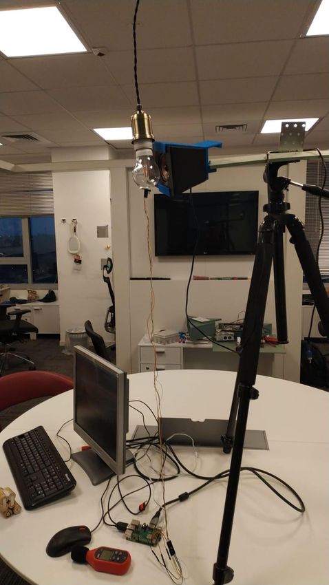
Measuring a Bulb’s Vibrations
By analyzing the results, we conclude that the angle of vibrations:
• is in millidegrees (0.005-0.06 degrees)
• is not equal - changes as a function of the frequency
• increases as the volume increases

 37
Measuring a Bulb’s Vibrations
Based on the known formula of the spherical coordinate system,
we computed the total movement, taking into account: Phi, Theta, and distance
between the ceiling and the bottom of the hanging bulb.

 38
Measuring a Bulb’s Vibrations
Results
Sound affected the hanging bulb, causing it to vibrate at 300-950 microns
between the range of 100-400 Hz.

 39
Measuring a Bulb’s Vibrations
Results
Sound affected the hanging bulb, causing it to vibrate in n 300-950 microns
between the range of 100-400 Hz.

 40
Intensity of Light vs. the Bulb’s Angle
Experiment
• We directed an electro-optical
 sensor toward a hanging light bulb
 (when illuminated).
• We measured the voltage that was
 produced by the electro-optical
 sensor from various distances (100-
 950 cm).

 41
Intensity of Light vs. the Bulb’s Angle
Results
A different amount of voltage is
produced by the electro-optical
sensor when the sensor is placed 200
cm (3.5 V) than is produced when the
sensor is 600 cm (0.5 V) from the
bulb.

 42
Intensity of Light vs. the Bulb’s Angle
Results
A different amount of voltage is
produced by the electro-optical
sensor when the sensor is placed 200
cm (3.5 V) than is produced when the
sensor is 600 cm (0.5 V) from the
bulb.
However, we are interested in
measuring small movements of the
bulb rather than large movements of
the sensor.
 43
Intensity of Light vs. the Bulb’s Angle
Experiment
We directed an electro-optical
sensor to a hanging light bulb from
various distances (100-950 cm).

Results
For a difference of centimeter, a different
amount of voltage is produced by the
electro-optical sensor.

 44
Setting the Criteria
• We computed linear equations
 between two consecutive points
 on the graph.

 45
Setting the Criteria
• We computed linear equations
 between two consecutive points
 on the graph.
• Based on the linear equations, we
 computed the expected voltage
 resulting from displacements of
 300 microns (0.3 mm) and
 1000 microns (1 mm).

 46
Setting the Criteria

• A 16-bit ADC provides a sensitivity of 300 microvolts:

 47
Setting the Criteria

• A 16-bit ADC provides a sensitivity of 300 microvolts.
• Conclusion 1: A sensitivity of 300 microvolts is sufficient to recover the entire
 spectrum (100-400 Hz) from a distance of 200-300 cm, because the smallest
 vibration of 0.3 mm produces a difference of 300 microvolts.

 48
Setting the Criteria

• A 16-bit ADC provides a sensitivity of 300 microvolts.
• Conclusion 1: A sensitivity of 300 microvolts is sufficient to recover the entire
 spectrum (100-400 Hz) from a distance of 200-300 cm, because the smallest vibration
 of 0.3 mm produces a difference of 300 microvolts.
• Conclusion 2: In order to detect a bulb’s vibration from 300 cm away: 1) the
 sensitivity of the system needs to be increased, or 2) the signal obtained needs to be
 amplified. 49
What Exactly is Vibrating?
 Experiment
 We obtained optical measurements via the electro-optical sensor when playing
 sine waves from speakers in these two scenarios:

With a defuser covering the LED bulb Without a defuser covering the bulb

 50
What Exactly is Vibrating?
Results
The SNR decreases when a defuser
covers the light bulb.

Conclusion 1: The diaphragm is the
light bulb and not the defuser.

Conclusion 2: The defuser decreases
the SNR due to the fact it is aimed at
distributing the light uniformly.
 51
Light Intensity vs. Angle
Experiment
Obtaining optical measurements
via the electro-optical sensor when
no sound is played near the light bulb.

 52
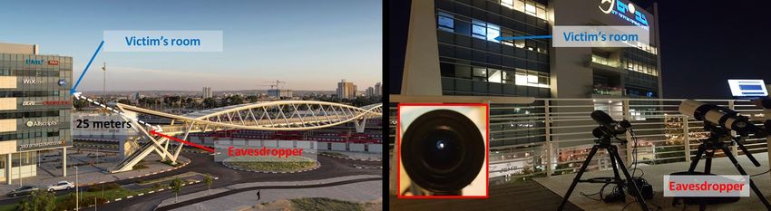
Light Intensity vs. Angle
Results
The defuser does not distribute
the light uniformly.

Side note:
If the defuser was able to perfectly
distribute the light uniformly, then
we were unable to detect the small
light changes that are the result of
displacements of microns. 53
Comparison of Various Types of Bulbs
Experiment
We compared the SNR that was obtained from three types of E27 light bulbs:

Incandescent LED Fluorescent

 54
Comparison of Various Types of Bulbs
Results
1) Sound could be reconstructed from
 every type of hanging light bulb that
 was examined.
2) The SNR of incandescent and LED
 light bulbs is higher than the SNR
 of fluorescent bulbs.

 55
Evaluation
in a Real Setup
 56
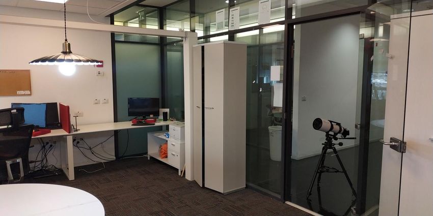
Experimental Setup
• We evaluated Lamphone’s performance for recovering sound from a bridge
 located 25 meters from an office.
• The office contains a 12 watt E27 hanging light bulb.

 57
Experimental Setup
 The sound that was
 played inside the office
 cannot be heard from
 the bridge.

 58
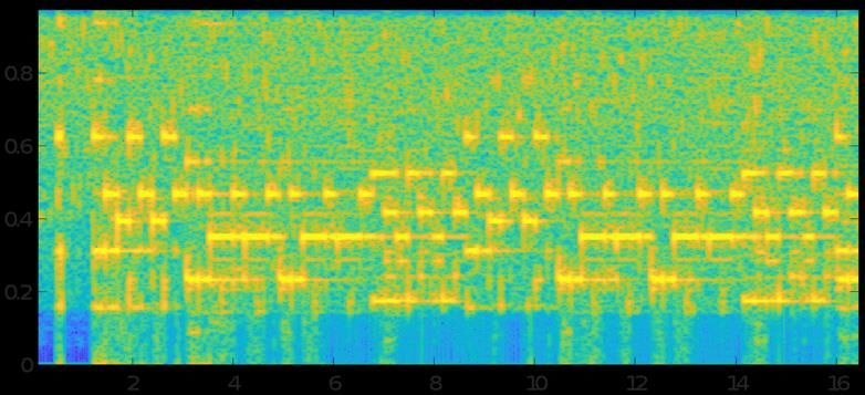
Characterizing the Baseline
Experiment
Obtaining optical measurements
via the electro-optical sensor when
no sound is played in the office.

 59
Results Results • The LED bulb works at 100 Hz. There are Peaks on the FFT graph at each of the harmonics (200 Hz, 300 Hz, etc.). No curtain walls We need to filter this noise with bandstop filters. • There is noise at low frequencies (below 50 Hz). We need to filter this noise with a highpass filter. 60
Analyzing the Frequency Response
Experiment
Obtaining optical measurements
via the electro-optical sensor when a
frequency scan is played via speakers
in proximity to a hanging bulb.

 61
Results

Conclusion 1: The SNR improves when a telescope with a bigger lens is used.
Conclusion 2: The SNR is not equal across the spectrum so an equalizer needs to be
applied in order to balance the frequency response of the recovered signal. 62
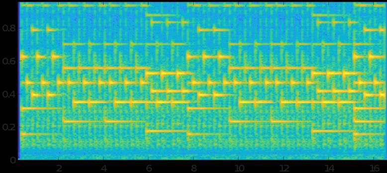
Recovering Non-Speech Audio
Experiment
• We played two famous songs inside the office:
 • "Let it Be” (The Beatles)
 • "Clocks” (Coldplay)
• We obtained the optical measurements.
• We recovered the signals.

 63
Recovering Non-Speech Audio
 Results

 Clocks - opt (t) Clocks - snd* (t) Clocks - snd (t)
Frequency (kHz)

 Let it be - opt (t) Let it be - snd* (t) Let it be - snd (t)
Frequency (kHz)

 Time (s) Time (s) Time (s)

 64
Recovering Non-Speech Audio
Results

We Shazamed the recovered
signals.

 65
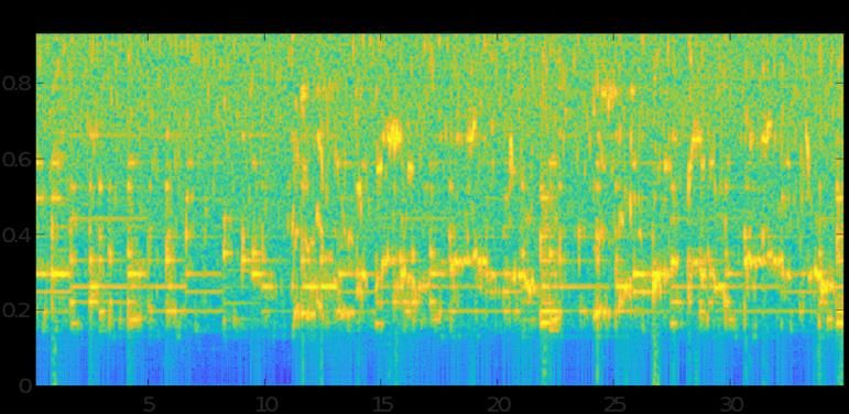
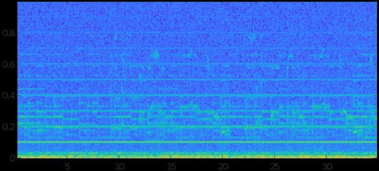
Recovering Speech Audio
Experiment
• We played a famous statement made by Donald Trump:
 • “We will make America great again!”
• We obtained the optical measurements.
• We recovered the signals.

 66
Evaluation
 Results

 “Wewill
 “We willmake
 makeAmerica…”–
 America…” -opt
 opt(t)
 (t) “We will make America…” - snd*(t) “We will make America…” - snd (t)
Frequency (kHz)

 Time (s) Time (s) Time (s)
Evaluation
Results
We investigated whether the recovered signal could be transcribed by Google’s
Speech-to-Text engine.

 68
Potential
Improvements
 69
Potential Improvements
1. Telescope
 • Using a telescope with a larger lens diameter (r).
 Why?
 The amount of light that is captured by the
 telescope is a function of its lens area ( 2 )
Potential Improvements
1. Telescope
 • Using a telescope with a larger lens diameter (r).
2. Electro-Optical Sensor
 • Using a better (more sensitive) electro-optical sensor than the one we used (PDA100A2).
 • Using multiple electro-optical sensors for multi-channel audio recovery.
Potential Improvements
1. Telescope
 • Using a telescope with a larger lens diameter (r).
2. Electro-Optical Sensor
 • Using a better (more sensitive) electro-optical sensor than the one we used (PDA100A2).
 • Using multiple electro-optical sensors for multi-channel audio recovery.
3. ADC
 • Using an ADC with a lower noise level.
 • Using a 24/32-bit ADC instead of a 16-bit ADC.
4. Recovery Algorithm
 • Using advanced filtering techniques to filter noise (e.g., deep learning).
Takeaways

 74
Primary Takeaway
Although it is now August 2020, please mark August 2026 on your calendars.
Why?
Let’s examine Gyrophone’s [1] scientific progress.
Primary Takeaway Although it is now August 2020, please mark August 2026 on your calendars. Why? Let’s examine Gyrophone’s [1] scientific progress. • 2014 – The attack vector of eavesdropping via motion sensors is revealed. A classification model to classify isolated words that yields results which are only slight better than a random guess Practicality The attack vector relied on speech at high volume. Gyrophone [1] 76 Time 2014
Primary Takeaway Although it is now August 2020, please mark August 2026 on your calendars. Why? Let’s examine Gyrophone’s [1] scientific progress. • 2014 – The attack vector of eavesdropping via motion sensors is revealed. • 2015 to 2018 – Increased understanding regarding this attack vector is gained. The accuracy of the classification model Practicality AccelWord [2] improves. Better understanding regarding Speechless [3] the experimental setup is gained. Gyrophone [1] 77 Time 2014 2015 2017
Primary Takeaway Although it is now August 2020, please mark August 2026 on your calendars. Why? Let’s examine Gyrophone’s [1] scientific progress. • 2014 – The attack vector of eavesdropping via motion sensors is revealed. Learning-based • 2015 to 2018 – Increased understanding smartphone regarding this attack vector is gained. eavesdropping [4] • 2020 – The attack vector is improved to Practicality AccelWord [2] make it a real and practical threat to privacy. A classification model with excellent accuracy. Speechless [3] The attack vector relies on speech at normal volume. Gyrophone [1] 78 Time 2014 2015 2017 2020
Primary Takeaway
Conclusion: It took scientists six years to
improve Gyrophone, to the point that it
now poses a real threat to privacy.

 79
Primary Takeaway
Conclusion: It took scientists six years to
improve Gyrophone, to the point that it
now poses a real threat to privacy.

My Forecast: I expect that by 2026, ?????

 Practicality
scientists will have improved Lamphone Lamphone
so that it too poses a real threat to Visual
 Microphone
privacy.
 Time
 2014 2020 2026

 80
Thank You!

Questions?
 81
Bibliography
[1] Y. Michalevsky, D. Boneh, and G. Nakibly, “Gyrophone: Recognizing speech from gyroscope signals,”
in 23rd USENIX Security Symposium (USENIX Security 14). San Diego, CA: USENIX Association, 2014, pp.
1053–1067.
[2] L. Zhang, P. H. Pathak, M. Wu, Y. Zhao, and P. Mohapatra, “Accelword: Energy efficient hotword
detection through accelerometer,” in Proceedings of the 13th Annual International Conference on
Mobile Systems, Applications, and Services. ACM, 2015, pp. 301–315.
[3] S. A. Anand and N. Saxena, “Speechless: Analyzing the threat to speech privacy from smartphone
motion sensors,” in 2018 IEEE Symposium on Security and Privacy (SP), vol. 00, pp. 116–133. [Online].
[4] Z. Ba, T. Zheng, X. Zhang, Z. Qin, B. Li, X. Liu, and K. Ren, “Learning-based practical smartphone
eavesdropping with built-in accelerometer.” Proceedings of the Network and Distributed Systems
Security (NDSS) Symposium 2020.
[5] M. Guri, Y. Solewicz, A. Daidakulov, and Y. Elovici, “Speake(a)r: Turn speakers to microphones for fun
and profit,” in 11th USENIX Workshop on Offensive Technologies (WOOT 17). Vancouver, BC: USENIX
Association, 2017. [Online]. 14.

 82
Bibliography
[6] N. Roy and R. Roy Choudhury, “Listening through a vibration motor,” in Proceedings of the 14th
Annual International Conference on Mobile Systems, Applications, and Services, ser. MobiSys ‘16. New
York, NY, USA: ACM, 2016, pp. 57–69.
[7] A. Kwong, W. Xu, and K. Fu, “Hard drive of hearing: Disks that eavesdrop with a synthesized
microphone,” in 2019 2019 IEEE Symposium on Security and Privacy (SP). Los Alamitos, CA, USA: IEEE
Computer Society, May 2019.
[8] R. P. Muscatell, “Laser microphone,” Oct. 25 1983, US Patent 4,412,105.
[9] Davis, A., Rubinstein, M., Wadhwa, N., Mysore, G. J., Durand, F., & Freeman, W. T. (2014). The visual
microphone: Passive recovery of sound from video.

 83
You can also read