Evo External Screen Awnings
     Installation Manual
←
→
Page content transcription
If your browser does not render page correctly, please read the page content below
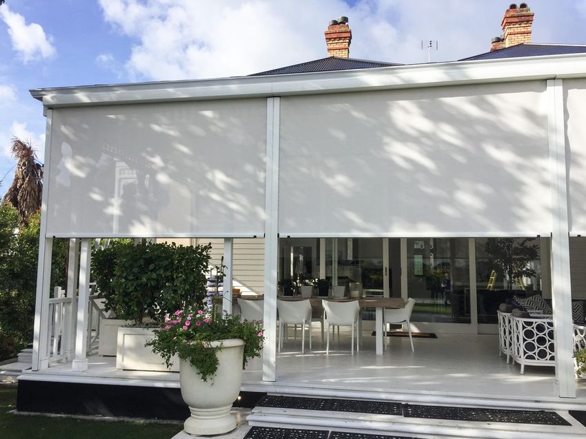
Evo External Screen Awnings
Installation Manual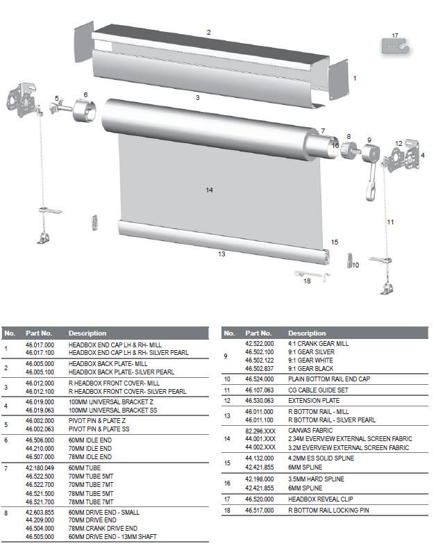
This Product Manual is only a guide to the measurement and installation.

New Zealand Window Shades Limited does not warrant the accuracy contained in
this manual.

The information contained in this Product Manual is based on the measurement and
installation data known to us at the time of issue of the Product Manual and is therefore
subject to changes or amendments at any time without notice, and the right to
change or amend is hereby expressly reserved by New Zealand Window Shades
Limited.

IMPORTANT
This Product Manual at all times remains the property of New Zealand Window Shades
Limited.
Its contents are strictly confidential and may not be reprinted, copied, reproduced or
multiplied in any form. This Product Manual must be maintained in its original form and
must be returned to New Zealand Window Shades Limited upon first request. New
Zealand Window Shades Limited is not responsible to you or anyone else for any loss
suffered in connection with the use of this product manual or any of the content.

SAFETY & WARNING ADVICE
A minimum of 2 people is necessary for proper installation.

PLEASE NOTE:
Installation fixings will NOT be supplied with any of the EVO Awning Series. Please refer
to fixing section. Each installation should be assessed on a case by case scenario.

WARNING! - The brackets must be fixed solidly to a substantial surface. Hollow bricks or
foam products are not suitable. Brick veneer surfaces require at least 2 courses of
brickwork above the bracket and 2 courses below.

GENERAL ADVICE
The electrical data is shown on the label of electric operating awnings.

Tools: The following tools are required for installation:

   •   Level
   •   Battery Drill
   •   Screwdrivers
   •   Hammer Drill
   •   Drill Bits
   •   Spanner - 7mm (size of open-end spanner for top aligner)
   •   Allen Key

2|Page
FIXINGS
Due to possible differences in specification, application and interpretation of results,
users must make their own evaluation of the product to determine the suitability of
fixings and their intended use.

  ITEM                             TITLE                             DESCRIPTION
                              Counter Sunk
                              (Zenith) 10g x
                                                             Used to side fix channels.
                              50mm
                              Available in Metal or Timber
                              thread Stainless

                              Waffer/Button Head
                              (Buildex) 8g x 50mm            Used to face fix channels.
                              Available in Metal or Timber
                              thread

                              Roofing       &
                              Cadding     Hex
                                                             Used to fix universal brackets.
                              Head (Buildex)
                              12g x 50mm
                              Available in Metal or Timber
                              thread
                              Counter Sunk
                              (Zenith) 10g x                 Used to fix wire guide bottom
                              50mm                           bracket.
                              Available in Metal or Timber
                              thread Stainless

                              Ramplug/Green Plug
                                                             Used to fit to brick or concrete
                              (Ramset) 50mm Length

                              Dyna Bolt
                                                             Used to face fix channels.
                              (Ramset) 6m x
                              30mm

                              Dyna Bolt
                                                             Used to fix universal brackets.
                              (Ramset) 8mm x
                              50mm

                              Counter Sunk
                                                             Used to fix wire guide bottom
                              (Ramset) 4.5mm x
                                                             bracket.
                              30mm Stainless

3|Page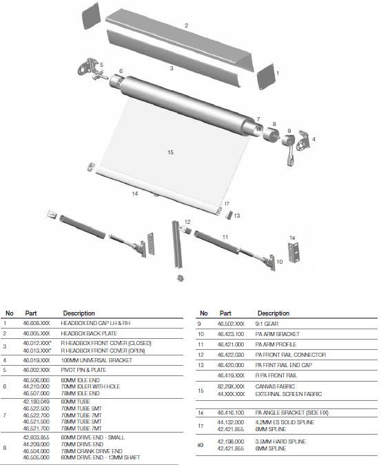
CHARATERISTICS OF AWNING FABRICS
Some slight fabric curling may occur on fabric edge on large applications, whilst the
following characteristics are considered normal occurrences.

   •   Creasing (Figs. 1, 2)
   •   Puckering (Figs. 3, 4 & 5)
   •   Tension Induced Stretching (Figs. 6)

OPTIONS & LIMITATIONS

                          CRANK GEAR          MOTORISED

 OVERALL MAX WIDTH           5000mm            5000mm

 OVERALL MAX DROP            4000mm            4000mm

 OVERALL MIN DROP            300mm             300mm

       MAX AREA              16 Sqm            16 Sqm

4|Page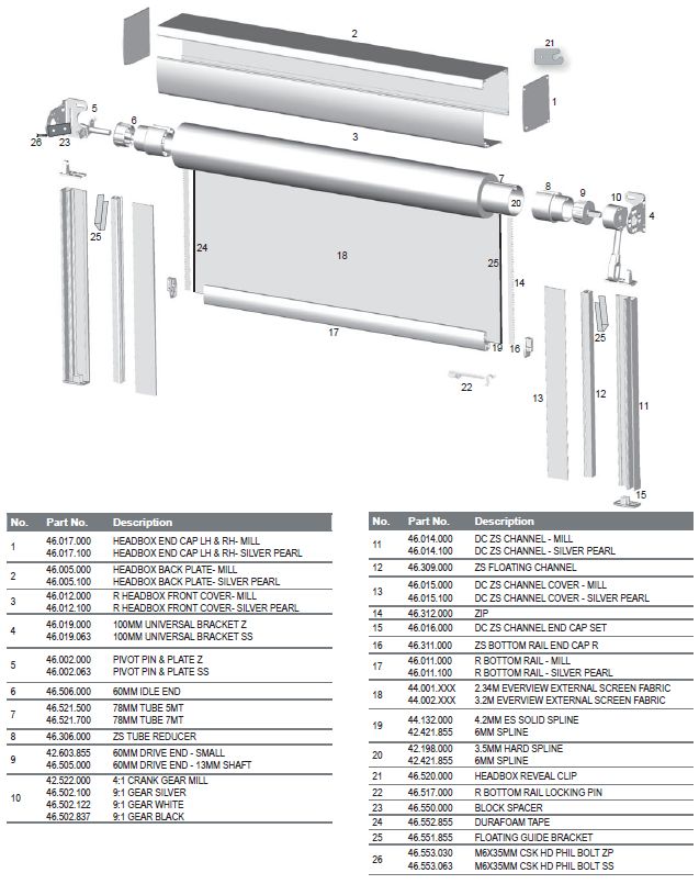
MEASURING INSTRUCTIONS
Accurate measuring of the EVO Awning Series is vital for successful fitting and
consequential use. The product can be fitted on Face or Inside fixing applications
and can be operated by crank control or Automation.

COMPONENT DIMENSIONS

              CABLE GUIDE                                  HEADBOX

    UNIVERSAL INSTALLATION BRACKET                        BOTTOM RAIL

            STC SIDE CHANNEL                        BOTTOM CABLE BRACKET

         PIVOT ARM FRONT RAIL

5|Page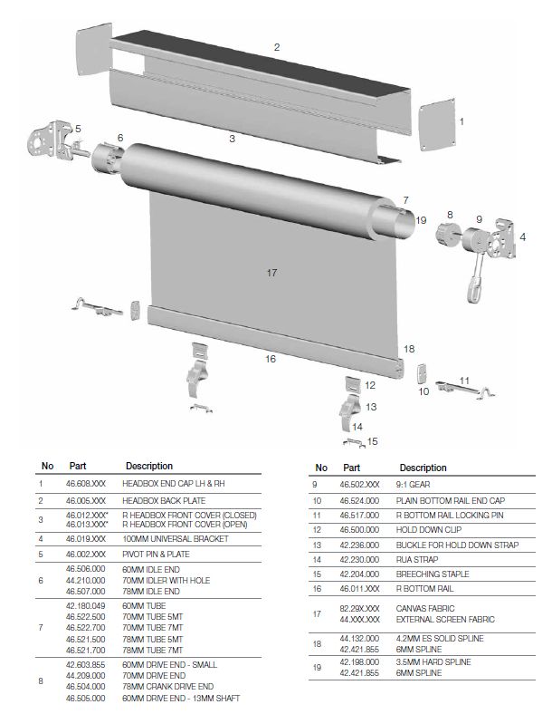
OPEN ROLLER INSTALLATION

   STEP 1 - MARK FIXING HOLES FOR THE FIRST BRACKET

              STEP 2 - DRILL FIXING HOLES

          STEP 3 - INSTALL THE FIRST BRACKET

           STEP 4 - MEASURE OVERALL WIDTH

 STEP 5 - REPEAT STEPS 1, 2 & 3 FOR THE SECOND BRACKET

6|Page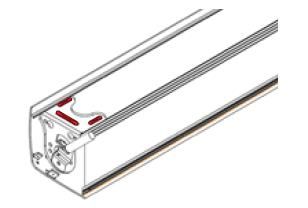
STEP 1/2/3/ - FACE FIT INSTALL

                IDLE END                                      DRIVE END
                                   REVEAL FIT INSTALL

                IDLE END                                      DRIVE END
                                  CEILING FIT INSTALL

                IDLE END                                      DRIVE END

Brackets will come pre-assembled with idle and drive end components attached.
The orientation of these components on the brackets will be determined by the
fixing orientation specified on the order form. Example: Face/Reveal, Ceiling.
     • Mark the fixing holes for the first bracket.
     • Drill holes to suit the method of fixing determined by the substrate being fixed
        to.
     • Screw the first bracket in place. Ensure the bracket is installed straight using a
        spirit level. If required, pack out the bracket.
     • Repeat process for the second bracket.
     • Ensure both brackets are installed level and the distance apart is enough for
        the roller tube to be inserted. The distance between the brackets should be
        the ordered overall measurement from outside of bracket to outside of
        bracket.

7|Page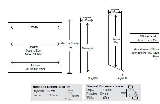
HEADBOX INSTALLATION

              STEP 1 - OPEN THE HEADBOX

             STEP 2 - REMOVE ROLLER TUBE

     STEP 3 - MARK & PRE-DRILL HEADBOX BACK PANEL
      - MARK FIXING HOLES ON INSTALLATION SURFACE
       DRILL FIXING HOLES ON INSTALLATION SURFACE
          - INSTALL HEADBOX THROUGH BRACKETS

                     ACCESSORIES
             INSTALLATION SPREADER PLATE
  PLEASE REFER TO RELEVANT SECTION FOR INSTRUCTIONS

8|Page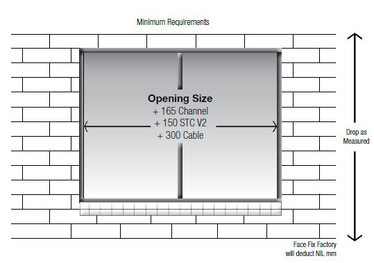
STEP 1 - OPEN THE HEADBOX                STEP 2 - REMOVE ROLLER TUBE

Open the headbox front cover by
unscrewing the bottom screw on the
headbox end cap. Repeat on opposite     Pull out the idle end locking pin and
side.                                   remove the roller tube idle end first.
Note: For reveal fit, the screw is no
longer required

                           STEP 3 - FACE FIT INSTALL

              IDLE END                                  DRIVE END
                          STEP 3 - REVEAL FIT INSTALL

              IDLE END                                  DRIVE END

9|Page
STEP 3 – CEILING FIT INSTALL
IDLE END DRIVE END
Mark and drill the head box back plate where the fixings will go.
NOTE: Always secure the headbox back panel through the installation brackets or
spreader plate!
• After determining the exact position of the headbox you can fasten the
brackets and headbox on the installation surface.
• Mark the fixing holes for the first bracket.
• Drill holes to suit the method of fixing determined by the substrate being fixed
to.
• Secure installation screw in bracket to hold one side of head box.
• Repeat the process for the opposite bracket and ensure that the head box is
straight using a spirit level.
NOTE: If required pack out the headbox.
• Once satisfied the headbox is level, secure remaining fixing points.
NOTE: For awnings over 3500mm wide, add an additional fixing point through the
centre of the headbox back panel.
E.g. 3500mm wide secure at 1750mm.
ACCESSORIES
SPREADER PLATE OPEN HEADBOX CLOSED HEADBOX
If there is no substantial fixing point at the
ends of the headbox, a Spreader Plate
can be added. This allows 250mm of
flexibility for installation points at each
A 4.5mm hole needs to be drilled in the
end of the awning. If a spreader plate is
headbox cover in REVEAL applications.
ordered, this will come preassembled to
Location of hole, refer to diagram above.
the bracket inside the headbox
determined by the installation type
specified. Secure through Fixing points
highlighted in the image.
10 | P a g eINSTALLING THE ROLLER TUBE
STEP 1 - INSTALL THE DRIVE END
STEP 2 - INSTALL THE IDLE END
OPTIONAL: STEP 3 - ATTACH THE HEABOX COVER
11 | P a g eSTEP 1 - MOTORISED STEP 1 - CRANK
Motorised - Insert motor into motor
Crank - Insert crank pin into crank gear
bracket then secure using motor clip
STEP 2 - INSERT PIVOT PIN STEP 3 - INSTALL THE ROLLER
Lift Roller over the installation bracket
and down so pivot pin sits inside the
pivot plate. Insert idle locking pin to
Insert Pivot Pin into idle end on tube secure roller.
*Operate the awning a couple of times
to ensure tracking and correct
operation of the awning
OPTIONAL: STEP 4 - ATTACH THE HEADBOX FRONT COVER
Once satisfied, reattach the headbox front cover
12 | P a g eEVO STRAIGHT DROP 13 | P a g e
EVO STRAIGHT DROP INSTALLATION
                             STEP 1
                  i - OPEN ROLLER INSTALL
                     ii - HEADBOX INSTALL

                          STEP 2
                   INSTALL ROLLER TUBE

                              STEP 3
               i - INSTALL HOLD DOWN STRAPS
                   ii - INSTALL LOCKING BOLTS

14 | P a g e
STEP 1 - INSTALL HEADBOX OR OPEN STEP 2 - INSTALL THE ROLLER TUBE
ROLLER
Refer to the following sections for Refer to installing the roller section
instructions:
i - Open Roller install
ii - Headbox Install
STEP 3 - INSTALL HOLD DOWN STRAPS
In order to protect the hold down clips, they will be supplied uninstalled from the
bottom rail.
Remove Bottom Rail end cap
- Insert ALL Hold down clips with strap, buckle and dog clip attached.
- Lower awning to desired fixing height.
- Slide hold down clips and straps to desired hold down locations.
- Reattach bottom rail end cap.
- Fix breeching staple to floor or wall surface under hold down straps.
- Use dog clip to attach hold down to breeching staple.
STEP 3 ii – INSTALL LOCKING BOLTS TO STEP 3 iii - INSTALL LOCKING BOLTS USING
REVEAL POST BREECHING STAPLE
The locking bolts will be supplied pre-
The locking bolts will be supplied pre-
installed in the bottom rail
installed in the bottom rail
Secure using Breeching Staple
Secure to Reveal post
- Lower awning to desired fixing
- Lower awning to desired fixing height.
height.
- Slide locking bolts out to desired fixing
- Slide locking bolts out to desired
location
fixing location
- Line up locking bolts with the posts
- Place breeching staple to floor or
and ensure the bottom rail is level.
wall surface to ensure the locking
- Mark fixing holes on post and drill using
bolt can be secured under the
a 12mm drill bit.
breeching staple.
- Slide locking bolts into the hole and
- Ensure the bottom rail is level. If not,
apply tension to ensure a level
pack out breeching staple to ensure
installation.
bottom rail will be perfectly horizontal
- Holes can be drilled at a variety of
when secured.
different stopping locations along the
- Fix breeching staple to floor or wall
post dependent on consumer
surface.
requirements
15 | P a g eEVO CABLE GUIDE 16 | P a g e
EVO CABLE GUIDE INSTALLATION

                                   STEP 1
                        i - OPEN ROLLER INSTALL
                           ii - HEADBOX INSTALL

               STEP 2 - INSTALL THE BOTTOM CABLE BRACKET

          STEP 3 - INSTALL THE CABLE & FLOATING END CAP

                   STEP 4 - APPLY TENSION TO THE WIRE

                    STEP 5 - INSTALL THE ROLLER TUBE

      STEP 6 - CONNECT FLOATING END CAP TO BOTTOM RAIL

                       ACCESSORIES
              NOTE: OPTIONAL EXTRAS INCLUDE
                     HOLD DOWN CLIPS
                       SLIDING BOLT
    PLEASE REFER TO RELEVANT SECTION FOR INSTRUCTIONS

17 | P a g e
STEP 1 - INSTALL HEADBOX OR OPEN STEP 2 - PREPARE THE BOTTOM CABLE
ROLLER BRACKET
Refer to the following sections for Use a string line or sprit level from the
instructions edge of the blind bracket or side of the
i - open roller install headbox to determine the correct
ii - headbox install location of the wire guide bottom
NOTE: cable guide installation bracket will bracket.
come with top cable bracket pre- NOTE: The bottom bracket is universal
attached and can be used for wall, floor or reveal
mounting.
- Remove the Eclip from the barrel
using screw driver or pointy nose
plyers.
- unscrew the bottom tension pin from
the bottom of the wire.
- remove the barrel from the bracket.
STEP 2 B - INSTALL THE BOTTOM CABLE
STEP 2 C - SECURE THE BARREL
BRACKET
Place the bottom cable bracket on the Once bracket is fixed to ground/wall,
location mark and fix into place with the slide in barrel, ensure the “lip” of barrel is
appropriate fixings. facing towards the awning fabric. Insert
the Eclip around the “lip” of the barrel
to ensure the barrel is secure.
STEP 3 A - ATTACH WIRE TO BOTTOM STEP 3 B - ATTACH FLOATING END CAP
BRACKET TO WIRE
18 | P a g eOnce bracket is fixed to ground/wall, Unwind the wire and feed floating end
slide in barrel, ensure the “lip” of barrel is cap onto the wire.
facing towards the awning fabric. Insert
the Eclip around the “lip” of the barrel to
ensure the barrel is secure.
STEP 4 A - ATTACH WIRE TO TOP CABLE STEP 4 B – APPLY TENSION TO THE WIRE
BRACKET
Feed wire through the top cable Return to the bottom bracket and use 2
brackets. Pull the wire tight. Lock off with pairs of pliers to tighten the tension pin
a 4mm Allen key. Ensure the grub screw is by holding the wire with one pair of
secured tightly. pliers and turn the pin with the other
pair. Repeat on opposite side.
STEP 6 - CONNECT FLOATING END CAP
STEP 5 - INSTALL THE ROLLER TUBE
TO BOTTOM RAIL
Refer to installing the roller tube section
Once the awning is installed lower the
awning to a position where it can be
reached from the ground. Tilt the
awning and insert the floating end cap
into bottom rail. Repeat for other side.
ACCESSORIES
OPTIONAL: HOLD DOWN STRAPS OPTIONAL: LOCKING BOLTS
In order to protect the hold down clips The locking bolts will be supplied pre-
they will be supplied uninstalled from the installed to the bottom rail
bottom rail. - Lower awning to the bottom cable
- Remove Bottom Rail end cap guide brackets.
- Insert ALL Hold down clips with strap, - Slide locking bolts into the bottom
buckle and dog clip attached. cable guide bracket and apply
19 | P a g e- Lower awning to desired fixing height. tension to ensure a level installation. If
- Slide hold down clips and straps to not level, pack out bottom cable
desired hold down locations. guide bracket to ensure bottom rail
- Fix breeching staple to floor or wall will be perfectly horizontal when
surface under hold down straps. Use under tension.
dog clip to attach hold down to
breeching staple
20 | P a g eEVO SIDE TENSION CHANNEL (STC) 21 | P a g e
EVO STC INSTALLATION
                                  STEP 1
                       i - OPEN ROLLER INSTALL
                          ii - HEADBOX INSTALL

               STEP 2 - OPEN THE CHANNEL FRONT COVER

                 STEP 3 - REMOVAL OF FLOATING GUIDE

                 STEP 4 - POSITION THE SIDE CHANNEL

                 STEP 5 - INSTALL THE SIDE CHANNEL

                  STEP 6 - INSTALL THE ROLLER TUBE

         STEP 7 - FEEDING THE FABRIC INTO SIDE CHANNEL

    STEP 8 - POSITIONING THE FABRIC AND FLOATING GUIDES

                STEP 9 - ATTACHING THE FRONT COVER

                       ACCESSORIES
              NOTE: OPTIONAL EXTRAS INCLUDE
                     HOLD DOWN CLIPS
                       SLIDING BOLT
    PLEASE REFER TO RELEVANT SECTION FOR INSTRUCTIONS
22 | P a g e
STEP 1 - INSTALL HEADBOX OR OPEN ROLLER
Refer to the following sections for
instructions:
i - Open Roller install
ii - Headbox Install
STEP 2 - OPEN THE CHANNEL FRONT COVER
The installation channel will be supplied fully assembled
(Back Channel, Floating Channel, Front channel with
Top and Bottom channel caps attached.
Check if front cover fixing Slide front cover towards Front cover can then be
screws at top of bottom middle of blind about removed by lifting towards
end caps are used, if so 12mm where it will stop. user.
remove screws. This operation can be per-
Note: An installed awning formed on either end of
will have these in place. channel.
STEP 2 – REMOVAL OF FLOATING GUIDE
STEP 2 - OPEN TH
E CHANNEL FRONT COVER
Lift black floating guide Pull floating guide towards user and lower guide so
towards top of channel bottom end comes out first.
about 2mm and tilt Note: If this cannot be removed loosen bolt on top end
bottom guide towards cap.
middle of awning.
23 | P a g eSTEP 4 - POSITION THE SIDE CHANNEL i) Face Fit with or without headbox Remove the rear bracket Position the side channel ii) Ceiling fit with headbox locator tab on the top using the remaining No bracket locator tab on end cap (if headbox). bracket locator tab the top end cap is used. Remove front bracket and/or the bottom screw Position the side channel locator tab if there is no port locator on the top using the locator tab on headbox. end cap. the top end cap. iii) Ceiling fit without headbox No locator tabs on the top end cap are used. STEP 5 - INSTALL THE SIDE CHANNEL i) Face Fit Use a spirit level to ensure channel is vertical and using the fixing holes drill pilot holes for the 25mm fixing screws, then fasten in place. Note: To prevent damage to the channel, when drilling use a bump stop at the end of the drill. ii) Reveal Fit a) Drill pilot holes on the b) Drill the screw head c) Use spirit level to ensure middle rib at the same clearance hole at same channel is vertical and drill intervals as the face fixing locations above and pilot fixing hole through 24 | P a g e
holes on the side channel        continue through middle    the back plate and the
 back plate.                      rib to                     wall so the fixing screws
                                  make centre mark for       (self-drilling) can be used,
                                  force fixing hole.         then fasten in place.
 STEP 6 - INSTALL THE ROLLER TUBE
 Refer to installing the roller section
 1) Check side channels are parallel
 STEP 7 - FEEDING FABRIC INTO SIDE CHANNEL

 a) Lower the awning         b) Feed fabric into floating guide and slide up (Step 3
 100mm from top and feed     in reverse).
 fabric through the top      c) Make sure floating guide is fitted onto top end cap
 channel cap                 locator. There should be no more than 5mm between
                             the top end cap and the floating guide when resting
                             on the bottom end cap.
 STEP 8 - POSITIONING THE FABRIC AND THE FLOATING GUIDES

 ) Fully Lower and raise the blind to align the floating guides. While performing this,
 check the skin is centred on the awning. The edge of the skin must be close to the
 same position on both reducers on the tube. If not, remove skin and roller tube, re-
 centre then repeat alignment of floating guides. After lowering and raising skin
 tighten top end cap locating nut.
 b) With the skin lowered, fix the floating guide at the lowest point possible by:

 i) Pulling floating guide so   ii) Drill a 4mm hole through the 2.5mm pilot hole.
 fabric is just flat between
 the bottom rail cap and
25 | P a g e
the channel, drill a 2.5mm iii) Fasten the 25mm countersunk screws into floating
hole guide and channel so the head of the screw is no more
through the floating guide than 1mm proud of the other floating guide.
and the fixing plate.
Warning: Ensure you do
not drill through the whole
back plate.
iv) Repeat the steps above on the other side.
c) Repeat the process using the fixing hole closest to the middle of the side channel.
d) Raise and lower skin to check operation, adjust tension if required by
repositioning floating guide.
e) • Check the bottom rail for levelness. A tolerance of 5 to 6mm is acceptable.
• If bottom rail level is not within tolerance, roll the awning to the fully down position.
Then continue unrolling the blind so the fabric balloons out from the tube and till you
have access to the spline section of the skin.
• Pull the skin in the direction of the side of the bottom rail that is up. Move the skin 1
to 2mm then raise the awning to check for bottom rail evenness.
• Repeat above process if required.
STEP 9 - ATTACHING THE FRONT COVER
a) Raise skin so bottom rail is within 100mm of top end cap.
b) Align front cover on back plate so c) Fasten the front cover into position by
face is flush with side channel outer fixing the screws with a screwdriver
surface then slide into position. through the front cover at the top of the
bottom end caps.
ACCESSORIES
OPTIONAL: HOLD DOWN STRAPS OPTIONAL: LOCKING BOLTS
These instructions relate to fixing hold The locking bolts will be supplied pre-
down straps to other guiding options. installed to the bottom rail
In order to protect the hold down clips, - Lower awning to the bottom cable
they will be supplied uninstalled from the guide brackets.
bottom rail. - Slide locking bolts into the bottom
- Remove Bottom Rail end cap cable guide bracket and apply
- Insert ALL Hold down clips with strap, tension to ensure a level installation. If
buckle and dog clip attached. not level, pack out bottom cable
26 | P a g e- Lower awning to desired fixing height. guide bracket to ensure bottom rail - Slide hold down clips and straps to will be perfectly horizontal when desired hold down locations. under tension. - Fix breeching staple to floor or wall surface under hold down straps. - Use dog clip to attach hold down to breeching staple. 27 | P a g e
EVO PIVOT ARM

28 | P a g e
EVO PIVOT ARM INSTALLATION

                                       STEP 1
                            i - OPEN ROLLER INSTALL
                               ii - HEADBOX INSTALL

                    STEP 2 - INSTALL THE ROLLER TUBE

               STEP 3 -     ATTACH PIVOT ARMS TO FRONT RAIL

                          STEP 4 - INSTALL PIVOT ARMS

29 | P a g e
STEP 1 – INSTALL HEADBOX OR OPEN
STEP 2 - INSTALL THE ROLLER TUBE
ROLLER
Refer to the following sections for Refer to installing the roller section
instructions
i - open roller install
ii - headbox install
STEP 3 - ATTACH PIVOT ARMS TO FRONT
STEP 4 - INSTALL PIVOT ARMS
RAIL
Attach pivot arms to front rail Lower front rail 20mm below headbox or
NOTE: Arms should be positioned within brackets and ensure the tube and front
300mm of the ends of the bottom rail rail are parallel.
and should be of equal distance. - Mark fixing location of pivot arm
installation foot.
- Install pivot arms using screws.
NOTE: For EVO Pivot Awning Reveal
installations an angle bracket will be
provided to mount the pivot arm foot to.
The location of the angle bracket can
be determined using the above process.
30 | P a g eOPERATING INSTRUCTIONS Manual Operation of the awnings with Crank To extend the awning: • Insert end of crank handle into the drive gear winding mechanism. • Rotate crank clockwise until awning is fully extended. (Do not keep winding once resistance is felt). It is then recommended that you turn the crank anti clockwise slightly to reduce tension. To retract the awning: • Insert end of crank handle into gear winding mechanism. • Rotate anti-clockwise until awning is fully retracted. (Do not keep winding once resistance is felt.) Warning! Watch the screen fabric carefully when retracting the awning to ensure there are no obstructions or creasing of the fabric. Should any resistance be felt or visible signs of the fabric not rolling up straight, stop immediately and turn crank in opposite direction until fabric is clear and runs smoothly, then start retracting again slowly. Automation Operation of the awnings with Remote To extend the awning: • Press the appropriate button on the remote control. • The awning will extend until it reaches the preset fully extended position. • The motor will stop automatically. To retract the awning: • Press the appropriate button on the remote control. • The awning will retract until it reaches the preset fully retracted position. • The motor will stop automatically. Warning! For automatic operating awnings or accessories, please ensure these are switched off during periods of absence (e.g. holidays) or when the awning will be left unattended. 31 | P a g e
FULL BRICK ON FACE/BRICK VENEER

               Side Tension Channel Dimensions 73 x 37.5mm

32 | P a g e
ON FACE ARCHITRAVE REVEAL & TOP FIX (SIDE FIX) 33 | P a g e
You can also read