HURST COMP/PLUS SHIFTER - 2015 Ford Mustang
←
→
Page content transcription
If your browser does not render page correctly, please read the page content below
FORM 159 0205 07/15
                            HURST COMP/PLUS SHIFTER
                                2015 Ford Mustang
                    (Getrag MT82 six-speed manual transmission)
                                 Catalog #391 0205
                                       ©2015 by Hurst Performance

Thank you for purchasing the Hurst Comp/Plus Shifter. Once you open the box, you will notice
that this is not your typical shifter design. This unit utilizes a multi-link-type mechanism to
achieve the perfect combination for a short throw shifter, reducing shift throw by 38% from front
to back, while maintaing a smooth silky side-to-side shift that is barely reduced resulting in
close to full side-to-side resolution. A billet steel, chrome plated upper stick and a classic
white knob is included in this kit to bring the interior to life. Positioned in-line with the classic
Hurst chrome plated flat blade stick is a chrome plated trigger rod. This trigger rod not only
functions as part of the reverse lockout feature, but truly adds style points to the interior.

IMPORTANT! Installing the Hurst Comp/Plus Shifter requires moderate mechanical ability.
Read this instruction sheet completely first, so that you thoroughly understand it and can be-
come familiar with the procedure before attempting installation. Furthermore, this shifter has
been primarily designed as a “competition” and/or “race” shifter. While every effort has been
made to reduce the amount of objectionable transmission/driveline noise transmitted into the
interior of the vehicle, some vehicles may experience greater amounts than others. If this is
possibly objectionable or unsuitable to your intended type or style of driving, return this product
to your retailer for a refund prior to beginning installation.

WORK SAFELY! Perform this installation on a good clean level surface for maximum safety
and with the engine turned “off”. Ensure that the parking brake is set and that the vehicle will
not move if accidentally started. Allow sufficient time for the vehicle to cool prior to beginning
installation.

INSPECT! Using the parts list, ensure that all parts are present and free from objectionable
defects and/or blemishes prior to beginning installation. Every effort has been made to ensure
that these parts arrive to you in perfect and non-damaged order. However, Hurst Performance
will not accept returned parts due to cosmetic defect after they have been installed in a vehicle.

                                               PARTS

      Chrome Upper Stick                Classic Hurst White Knob                 Lower Stick

HURST PERFORMANCE                                                        www.HURST-SHIFTERS.com
                                                 1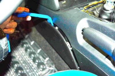
PARTS (CONTINUED)

        Shift Rod             Trigger Rod             Rev. Lock-Out Collar

        Cotter Pin         1/4” Flat Washer (2)       3/8” Lock Washer (2)

        Guide Nut            Spring Bracket                  Spring

  Spring Retaining Screw     8-32 Set Screw              Grease Packet

         Jam Nut              3/8” Washer             P-Urethane Bushing

HURST PERFORMANCE                                 www.HURST-SHIFTERS.com
                                  2
PARTS (CONTINUED)

         Loctite          3/8”-24 Cap Screw         3/8”-24 Guide Screw

        Pivot Bolt          1/4”-20 Screw                 Link (2)

   1/4” Shoulder Screw     1/4” Disc Spring        1/4” Flange Bearing (4)
                                  (2)

     10-24 Lock Nut           Swivel Link           3/16” Shoulder Screw

      8/32 Lock Nut      3/16” Sleeve Bearing            #8 Washer

HURST PERFORMANCE                               www.HURST-SHIFTERS.com
                                 3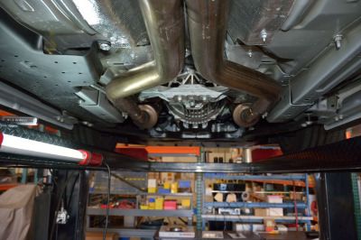
PARTS (CONTINUED)

     Nylon Washer          3/16” Disc Spring                Tie Wrap

                                               T OOLS

Plastic Trim Remover (2)     4mm Punch                      Hammer                  T-20 Torx Driver
        (Pry Tool)

     18mm Socket             Breaker Bar                1/4” Drive Ratchet           10mm Sockets

       Extension            Universal Joint              13mm Socket                 11/32” Wrench

   1/8” Allen Wrench          Craft Knife           7/32” Allen Wrench             Philips Screwdriver

HURST PERFORMANCE                                                            www.HURST-SHIFTERS.com
                                               4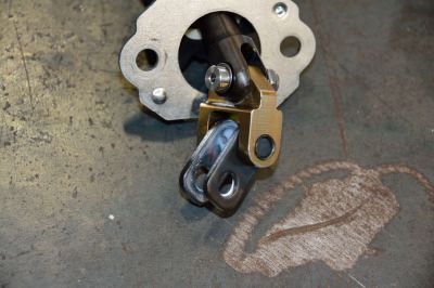
5/64” Allen Wrench   3/32” Allen Wrench       Torque Wrench              15mm Socket
                                                 (20-80 ft.lbs)

    7mm Socket               Jack                Jack Stands              10mm Wrench

    10mm Ratchet         Disc Grinder           Plastic Hammer               Pliers
       Wrench

        Vise               C-Clamp               3/4” Socket              7/16” Socket

  3/8” Drive Ratchet     Side Cutters

HURST PERFORMANCE                                                 www.HURST-SHIFTERS.com
                                            5
Disassembly
STEP 1. Unscrew the shift knob.
(counter-clockwise to remove.)
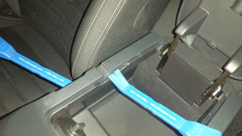
STEP 2. Remove the front driver side and passenger
side panels from the center console.
Tool: Plastic Trim Remover
STEP 3. Remove the two (2) screws from both sides of
the console.
Tools: 7mm Socket, Extension, Ratchet
STEP 4. Remove the center console. Start by lifting up
the rear and work your way up to the front.
Tool: Plastic Trim Remover x 2
HURST PERFORMANCE www.HURST-SHIFTERS.com
6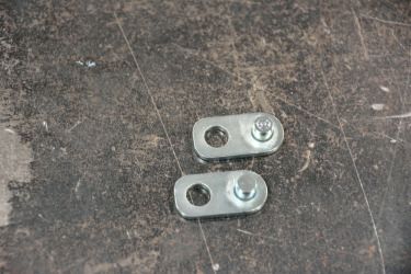
STEP 5. Unplug the harness from the console. Set
  console aside.

  STEP 6. Remove the spring retaining roll pin.

         Tools: 4mm Punch, Hammer

 STEP 7. Remove the retaining screw and then remove
 the factory reverse lockout sleeve.

         Tool: T20 Torx Driver

 STEP 8. Lift the vehicle. Support the vehicle with
 Jackstands if working with a floor jack.

HURST PERFORMANCE                                         www.HURST-SHIFTERS.com
                                                      7
STEP 9. Support the transmission.

         Tools: transmission stand or floor jack

 STEP 10. Remove the four (4) 18mm bolts securing
 the transmission to the frame. Lower the rear of the
 transmission. Support the rear with a transmission
 stand if you have the vehicle supported with a lift ;
 support the rear with a floor jack if you have the vehicle
 supported with jack stands.

         Tools: Breaker Bar, 18mm Socket, Ratchet,
                  Extension

 STEP 11. Remove the three (3) 15mm bolts securing
 the crossmember to the transmission.

         Tools: Breaker Bar, 15mm Socket, Ratchet

                                                                                    REMOVE
                                                                                    THREE (3)
 STEP 12. Remove the three (3) 18mm bolts securing                                  18MM BOLTS
 the front end of the driveshaft to the transmission.
 IMPORTANT: Make an alignment mark between the
 Flex Coupling and the transmission flange. You must
 re-install the driveshaft in the same position as it was
 removed.

         Tools: 18mm Socket, Ratchet
                                                                FLEX
                                                              COUPLING

HURST PERFORMANCE                                                        www.HURST-SHIFTERS.com
                                                       8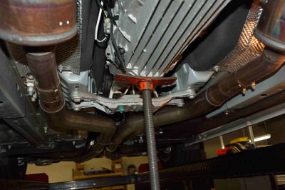
STEP 13. Remove the center bearing bolts.

         Tools: 13mm Socket, Ratchet

 STEP 14. Once the center bearing bolts have been
 removed, you can pull the driveshaft back and lower
 the front end of the driveshaft. Allow the driveshaft to
 rest on top of the exhaust.

 STEP 15. Remove the four (4) 10mm screws from the
 bottom of the shifter.

           Tools: 10mm Deep Socket, Universal
                    Adapter, Extension, 1/4” Drive
                    Ratchet

 STEP 16. Remove the two (2) 10mm hex nuts and
 remove the rear bushing assembly.

             Tools: 10mm Deep Socket, Universal
                     Adapter, Extension(s), 1/4” Drive
                    Ratchet

HURST PERFORMANCE                                               www.HURST-SHIFTERS.com
                                                            9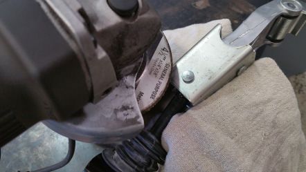
STEP 17. Remove the bottom plate. Do not discard the
 rubber gasket. You will need to re-use this when re-
 installing the shifter.

 STEP 18. Remove the shifter housing.

          Tools: 10mm wrench to break loose the screw,
 10mm ratchet wrench for ease of removal. You will have
 to pull down on the transmission to allow the screw to
 clear the tunnel.

 STEP 19. Remove the shift linkage.

         Tools: 13mm Socket, 3/8 “ Drive Ratchet

 STEP 20. The photo to the right is a close up of the
 screw removed from the shift linkage in step 19. Note
 that the screw is only partially threaded at the top. This
 is being mentioned so you dont spend too much time
 trying to loosen a screw that is already completely
 loose. After it is completely loose, it will need to be
 pulled free.

HURST PERFORMANCE                                             www.HURST-SHIFTERS.com
                                                       10
STEP 21. The shift rod has to be removed and
replaced with the new shift rod. The best way to do this
is to grind off the end with the smaller diameter head.
Once the head has been ground off, use a punch and a
hammer to remove the pin from the assembly.
Discard the pin. A new pin is included in the kit.
Tools: Disc Grinder, Punch, Hammer
grind head
STEP 22. The photo to the right shows the bolt
removed and the two parts seperated.
STEP 23. Remove the two (2) bushings and the rubber
boot from the old shift rod, being careful not to damage
them as they will be re-used.
Tools: Punch, Hammer
STEP 24. Carefully, install the rubber boot and two
(2) plastic bushings onto the new supplied shift rod.
Tool: Hammer
HURST PERFORMANCE www.HURST-SHIFTERS.com
11STEP 25. Remove the shifter retaining plate from the
bottom of the shifter housing.
Tools: 10mm Socket, Extension, Ratchet
STEP 26. Remove the shifter from the housing and
disassemble. Use a set of pliers to pry the small pivot
cup off of the small pivot ball. The larger pivot cup can
be removed by hand. The large pivot cup, the screws
and the plate will be re-used.
Tool: Pliers
STEP 27. Be sure to grease the main pivot ball of the
new supplied lower stick. Install the large pivot cup and
then install the plate.
STEP 28. Add grease to both sides of the swivel and
screw 8/32” locking nut
insert the swivel into the stick. Slip a disc spring and a
nylon washer onto the shoulder screw. Slide the 3/16” nylon washer
shoulder screw through the stick and the swivel. Secure 3/16” disc spring
the parts together with a 8-32 lock nut.
NOTE: add a drop of loctite to the thread of the shoulder
screw prior to install.
HURST PERFORMANCE www.HURST-SHIFTERS.com
12STEP 29. Insert a flange bushing into swivel, one (1) on
each side, as shown in the photo on the right.
STEP 30. Install the lower stick assembly up into the
shifter housing. Pay careful attention to the orientation
of the stick prior to install. The lower stick has two
faces. One face is flat while the other face has serra-
tions that will mate with the upper chrome stick, which
also has serrations. The face with the serrations should
be facing the passenger side once installed.
Tools: 10mm Socket, Ratchet
STEP 31. The photo to the right shows the correct
FLAT SERRATION
orientation of the stick once installed. If you have SIDE SIDE
installed it backwards, rotate the lower stick 180
degrees to correct the problem.
STEP 32. Add grease to the one face of the link,
opposite of the side with the pin and then insert a link
on each side of the swivel as shown in the photo on the
right.
HURST PERFORMANCE www.HURST-SHIFTERS.com
13STEP 33. Insert the new shift rod between the links.
You can add one of the rubber bushings onto the shift
rod at this point.
original
bushing
STEP 34. Insert a flanged bushing to each side of the
links, to semi-secure the links to the shifter.
STEP 35. Insert a 1/4” disc spring onto the 1/4” shoul- flange
der screw and slide it through one end of the links. bushing
1/4” screw
Once the screw is through to the other side, add disc spring
another 1/4” disc spring, and then a #10 washer. Secure disc spring
it together with a nyloc nut. This is important: You may #8 washer flange
need to adjust the tension between the nut and screw. lock nut bushing
You want to be able to rotate the links between the shift
rod, but it should be stiff. It should take some effort to
rotate. The shifter will not function properly if it is loose.
Tools: 3/32” Allen Wrench, 3/8” Wrench
NOTE: add a drop of loctite to the thread of the
shoulder screw prior to install.
STEP 36. Generously grease the shift rod to maintain
a slip fit. Add the second rubber bushing onto the shift
rod.
HURST PERFORMANCE www.HURST-SHIFTERS.com
14STEP 37. Re-apply the rubber gasket onto the cover or
the housing and secure the cover to the housing with
the four (4) 10mm screws.
Tools: 10mm Socket, Extension, Ratchet.
STEP 38. Install-Ready Shift Assembly Shown.
STEP 39. Install the shift linkage to the transmission.
Tools: 13mm Socket, 3/8 “ Drive Ratchet
STEP 40. Install the shifter assembly onto the
transmission.
Tools: 10mm Wrench, 10mm Ratcheting
Wrench
HURST PERFORMANCE www.HURST-SHIFTERS.com
15STEP 41. Insert the end of the shift rod into the shift pivot bolt
linkage. Add grease to the pivot bolt and slide it through
the linkage. Secure it with a washer, and a 1/4-20
screw.
Tools: 3/4” Socket, Ratchet, 7/16” Socket
STEP 42. Replace the rear bushing with the polyure-
thane bushing supplied with the kit. Insert it into the
bracket clip. You will need to form the clip bracket
around the new bushing to make it easier for install. The
holes need to be 4.21 inches apart to be re-installed. It
will be improbable that you will get it to hold at 4.21
inches apart, but try to get it close to 4.21 inches as
possible. You will rely on a pry bar to compress the
assembly during install.
STEP 43. Re-install the rear bushing assembly. Slip the
assembly on the housing first. Then insert one end of
the clip onto one of the studs.
STEP 44. Use a long pry bar to simultaneously
compress and push the other end of the clip onto the compress
other stud. Secure with the 10mm nuts.
Tools: Pry Bar, 10mm Socket, Extension,
Ratchet push pry bar
HURST PERFORMANCE www.HURST-SHIFTERS.com
16STEP 45. Slip the front end of the driveshaft back into
the transmission. Align the Driveshaft Flex Coupling to
the transmission flange.
alignment
marks
STEP 46. Re-install the bearing support.
Torque bolts to 35 ft. lbs
Tools: 13mm Socket, Extension,
Universal Adapter, Ratchet, Torque Wrench
STEP 47. Re-install the front end of the driveshaft.
Do not forget to align the driveshaft flex coupling to the
transmission flange prior to inserting the bolts.
Torque bolts to 81 ft.lbs
Tools: 18mm Socket, Ratchet,
Torque Wrench
STEP 48. Re-install the crossmember to the
transmission. Torque bolts to 76 ft. lbs
Tools: 15mm Socket, Ratchet,
Torque Wrench
HURST PERFORMANCE www.HURST-SHIFTERS.com
17STEP 49. Re-install the crossmember to the frame.
Torque bolts to 46 ft.lbs
Tools: 18mm Socket, Ratchet,
Torque Wrench
STEP 50. Remove the support stand.
STEP 51. Lower the vehicle.
chrome
STEP 52. Install the Upper Chrome Stick and Spring
lower stick
Bracket. The 3/8” guide screw will be inserted and
stick
installed into the bottom hole of the stick along with a spring
3/8” lockwasher and a 3/8” washer. bracket
Tool: 7/32” Allen Wrench screw
lock
washer
washer
HURST PERFORMANCE www.HURST-SHIFTERS.com
18STEP 53. Insert the Trigger Rod into the Reverse
Lockout Collar.
STEP 54. From the bottom, insert the 1/4” washer over
the bottom end of the Trigger Rod. Insert the cotter pin
through the hole in the Trigger Rod. Bend each leg of
the cotter pin 90 degrees and cut excess material. The
photo to the right is a bottom view of the assembly.
Please note the orientation of the cotter pin and the
approx. length of the legs.
Tools: Needle Nose Pliers, Wire Cutters
STEP 55. Align the Trigger Rod so that the top is
perpendicular to the opening in the Reverse Lockout
Collar. While maintaining the alignment, pull up on the
Trigger Rod so that it is at its highest position within the
Reverse Lockout Collar and secure it in position with
the set screw. NOTE: Add a drop of loctite to threads of
set screw to prevent set screw from backing out.
Tool: 5/64” Allen Wrench
set screw
STEP 56. Slip the Reverse Lockout Collar over the
sticks. Insert the 3/8” full threaded screw into the top
hole of the stick along with a 3/8” lockwasher and
tighten screw.
Tool: 7/32” Allen Wrench
HURST PERFORMANCE www.HURST-SHIFTERS.com
19STEP 57. Install the extension spring to the Reverse
Lockout Collar with the supplied Spring Retaining
Screw.
Tool: Philips Screwdriver
screw
STEP 58. Insert the other end of the spring onto the
Spring Bracket tab.
spring
bracket
tab
STEP 59. Add a drop of loctite to the internal threads of
the guide nut and install onto the end of the upper
screw. Test the Reverse Lockout Collar for proper guide nut
function. Pull up on the trigger rod and release. The
collar should spring back to its lowered position.
Tools: 5/8” Socket, Ratchet
STEP 60. To prevent premature wear to Reverse
Lockout Collar, apply grease to the shifter reverse block
and lock-out collar where the two will contact during
shifts to 1st and/or 2nd gear.
HURST PERFORMANCE www.HURST-SHIFTERS.com
20STEP 61. Install the rubber boot over shifter assembly.
The top lip should go over the bottom groove of the top lip
Reverse Lockout Collar. The bottom lip should seal
around the base of the shifter casting.
bottom
lip
STEP 62. Unsnap the shift boot bezel from the con-
sole. Lift from the top to release the top clips and then
use the pry tool to un-clip the rest.
Tool: Plastic Trim Remover Tool
STEP 63. Re-install the console.
NOTE: Do not forget to re-connect the harness. The
vehicle will not start if the harness is not re-connected.
STEP 64. The factory shift boot must be modified to fit
the Hurst Shifter. The collar must be removed from
the boot by carefully trimming the shift boot away from
the collar.
Tool: Craft Knife
HURST PERFORMANCE www.HURST-SHIFTERS.com
21STEP 65. Install the shift boot over the shifter and
secure the shift boot as shown in the picture to the right
with the supplied tie wrap. Cut excess material from tie
wrap.
Tool: Side cutters
STEP 66. Snap the shift boot bezel into the console.
STEP 67. Screw the jam nut down onto the upper stick
threads.
jam nut
upper
stick
STEP 68. Install the shift knob onto the stick. Align
the logo on the shift knob accordingly and tighten the
jam nut up against the knob. A few drops of Loctite will
help prevent the knob from loosening.
CAUTION! : Over tightening the knob down onto the
stick will eventually cause the knob to crack.
ALLOW LOCTITE TO DRY.
Tool: 9/16” Wrench
HURST PERFORMANCE www.HURST-SHIFTERS.com
22STEP 69. Re-install the two (2) screws on both sides
of the console.
Tool: 7mm Socket, Extension, Ratchet
STEP 70. Re-install the front driver side and passenger
side panels from the center console.
STEP 71. Start the engine. Go through all the gears
several times to confirm the shifter has been installed
correctly. Ensure that each gear can be engaged
smoothly and fully. Correct any problems before
operating vehicle. Enjoy!
HURST PERFORMANCE www.HURST-SHIFTERS.com
23Technical Service
A highly trained technical service department is maintained by Hurst Performance to an-
swer your technical questions, provide additional product information and offer various
recommendations.
Hurst offers a wide variety of custom T-Handles and knobs that can be used with this
shifter to allow the driver to tailor the vehicle to his/hers personal liking. See your local
retailer of Hurst products for specific prices.
Technical service calls, correspondence, and warranty questions should be directed to
the following address:
Hurst Performance
Phone: (707) 544-4761
Monday - Friday 6:00 AM to 5:00 PM PST
Saturday 7:30 AM to 5:00 PM PST
www.hurst-shifters.comYou can also read